
Create successful ePaper yourself
Turn your PDF publications into a flip-book with our unique Google optimized e-Paper software.
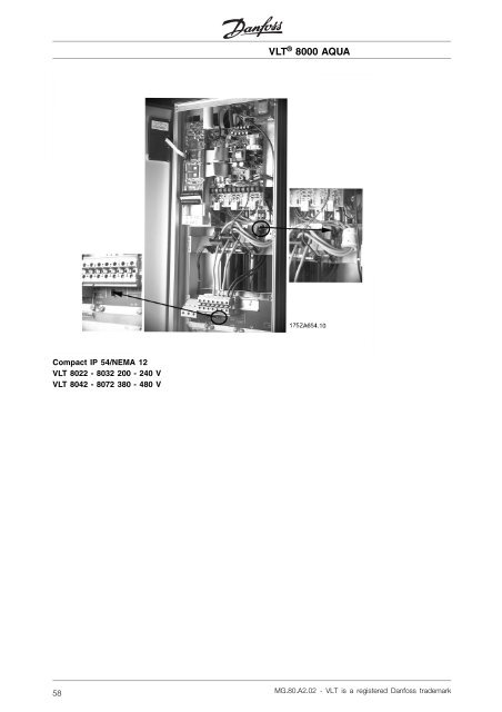
Compact IP 54/NEMA 12<br />
VLT 8022 - 8032 200 - 240 V<br />
VLT 8042 - 8072 380 - 480 V<br />
58<br />
VLT ® <strong>8000</strong> <strong>AQUA</strong><br />
MG.80.A2.02 - VLT is a registered Danfoss trademark
■ Mains connection<br />
Mains must be connected to terminals 91, 92, 93.<br />
Nos. 91, 92, 93 Mains voltage 3 x 200-240 V<br />
L1, L2, L3 Mains voltage 3 x 380-480 V<br />
Mains voltage 3 x 550-600 V<br />
NB!:<br />
Check that the mains voltage corresponds to the<br />
mains voltage of the VLT frequency converter,<br />
which can be seen from the nameplate.<br />
See Technical data for correct sizing of<br />
cable cross-sections.<br />
NB!:<br />
It is the responsability of the user or installer<br />
to ensure that proper earthing/grounding,<br />
branch circuit, and motor overload protection<br />
is in accordance with national and local electrical<br />
and safety regulations and codes.<br />
VLT ® <strong>8000</strong> <strong>AQUA</strong><br />
MG.80.A2.02 - VLT is a registered Danfoss trademark 59<br />
Installation
VLT ® <strong>8000</strong> <strong>AQUA</strong><br />
Customer Supplied Input Power Fuses for VLT frequency converters in UL/cUL Applications<br />
(Use specified fuse or exact replacement only)<br />
200 - 240 Volts � 380 - 480 V � 550-600 V �<br />
VLT<br />
Fuse type VLT type Fuse type VLT Fuse type<br />
type<br />
type<br />
8006 Bussmann KTN-R 50 8006 Bussmann KTS-R 20 8002 Bussmann KTS-R 3<br />
8008 Bussmann KTN-R 50 8008 Bussmann KTS-R258003 Bussmann KTS-R4<br />
8011 Bussmann KTN-R 50 8011 Bussmann KTS-R 30 8004 Bussmann KTS-R 5<br />
8016 Bussmann KTN-R 60 8016 Bussmann KTS-R 40 8005 Bussmann KTS-R 6<br />
8022 Bussmann KTN-R 80 8022 Bussmann KTS-R 40 8006 Bussmann KTS-R 8<br />
8027 Bussmann KTN-R 125 8027 Bussmann KTS-R 50 8008 Bussmann KTS-R 10<br />
8032 Bussmann KTN-R 125 8032 Bussmann KTS-R 60 8011 Bussmann KTS-R 15<br />
8042 4 Bussmann FWX 150 8042 Bussmann KTS-R 80 8016 Bussmann KTS-R 20<br />
8052 4 Bussmann FWX 200 8052 Bussmann KTS-R 100 8022 Bussmann KTS-R 30<br />
8062 4 Bussmann FWX 250 8062 Bussmann KTS-R 125 8027 Bussmann KTS-R 35<br />
8072 4 Bussmann FWH 150 8032 Bussmann KTS-R 45<br />
8100 4 Bussmann FWH 200 8042 Bussmann KTS-R 60<br />
8125 4 Bussmann FWH 250 8052 Bussmann KTS-R 75<br />
8150 4 Bussmann FWH 300 8062 Bussmann KTS-R 90<br />
8200 4 Bussmann FWH 350 8072 Bussmann KTS-R 100<br />
8250 4 Bussmann FWH 400 8100 FWP-125A<br />
8300 4 Bussmann FWH 500 8125 FWP-175A<br />
8350 4, 5 Bussmann FWH 600 8150 FWP-200A<br />
8450 4, 5 Bussmann FWH 700 8200 FWP-250A<br />
8500 4, 5 Bussmann FWH 800 8250 FWP-350A<br />
8600 4, 5 Bussmann FWH 800 8300 FWP-400A<br />
1. Fuses designed for protection in a circuit capable of supplying a maximum of 100,000 Amps rms<br />
(symmetrical), 250 V maximum.<br />
2. Fuses designed for protection in a circuit capable of supplying a maximum of 100 kA rms<br />
(symmetrical), 500 V maximum.<br />
3. Fuses designed for protection in a circuit capable of supplying a maximum of 100,000 Amps rms<br />
(symmetrical), 600 V maximum.<br />
4. Auxiliary Fan use Littelfuse KLK-15.<br />
5. Fuses are provided in units with Disconnect Option.<br />
Substitutions:<br />
Bussmann KTS-R Fuses can be substituted for Bussmann KTN-R Fuses of the same amperage.<br />
Bussmann FWH Fuses can be substituted for Bussmann FWX Fuses of the same amperage.<br />
Bussmann JJN Fuses can be substituted for Bussmann KTN-R Fuses of the same amperage.<br />
Bussmann JJS Fuses can be substituted for Bussmann KTS-R Fuses of the same amperage.<br />
On input power, Ferraz-Shawmut fuses, type ATMR, Class CC, up to 30 A max. may be used on all<br />
VLT series drives.<br />
60<br />
MG.80.A2.02 - VLT is a registered Danfoss trademark
VLT ® <strong>8000</strong> <strong>AQUA</strong><br />
Internal Fuses Provided with VLT <strong>AQUA</strong> frequency converters<br />
(Use specified fuse or exact replacement only)<br />
200-240 VAC<br />
VLT type Soft Charge Fuse<br />
Soft Charge Resistor Power Card Fuse<br />
(3X)<br />
(1X)<br />
(1X)<br />
8042 Littelfuse KLK-15 Littelfuse KLK-D-12 Bussmann KTK-5<br />
8052 Littelfuse KLK-15 Littelfuse KLK-D-12 Bussmann KTK-5<br />
8062 Littelfuse KLK-15 Littelfuse KLK-D-12<br />
380-480 VAC<br />
Bussmann KTK-5<br />
VLT type Soft Charge Fuse<br />
Soft Charge Resistor Power Card Fuse<br />
(3X)<br />
(1X or 2X)<br />
(1X)<br />
8072 Littelfuse KLK-15 Littelfuse KLK-D-12 (1X) Bussmann KTK-5<br />
8100 Littelfuse KLK-15 Littelfuse KLK-D-12 (1X) Bussmann KTK-5<br />
8125 Littelfuse KLK-15 Littelfuse KLK-D-12 (1X) Bussmann KTK-5<br />
8150 Littelfuse KLK-30 Littelfuse KLK-D-12 (1X) Bussmann KTK-5<br />
8200 Littelfuse KLK-30 Littelfuse KLK-D-12 (2X) Bussmann KTK-5<br />
8250 Littelfuse KLK-30 Littelfuse KLK-D-12 (2X) Bussmann KTK-5<br />
8300 Littelfuse KLK-30 Littelfuse KLK-D-12 (2X) Bussmann KTK-5<br />
VLT type Soft Charge Fuse<br />
Line Snubber Fuse Interface Board Fuse<br />
(3X)<br />
(3X)<br />
(1X)<br />
8350 Littelfuse KLK-9 Littelfuse KLK-15 Bussmann KTK-5<br />
8450 Littelfuse KLK-9 Littelfuse KLK-15 Bussmann KTK-5<br />
8500 Littelfuse KLK-9 Littelfuse KLK-15 Bussmann KTK-5<br />
8600 Littelfuse KLK-9 Littelfuse KLK-15<br />
550-600 V<br />
Bussmann KTK-5<br />
VLT type Soft Charge Fuse<br />
Soft Charge Resistor Power Card Fuse<br />
(3X)<br />
(1X or 2X)<br />
(1X)<br />
8100 AC Littelfuse KLK-15 AC Littelfuse KLK-D-12 (1X) Bussmann KTK-5<br />
8125 AC Littelfuse KLK-15 AC Littelfuse KLK-D-12 (1X) Bussmann KTK-5<br />
8150 AC Littelfuse KLK-15 AC Littelfuse KLK-D-12 (1X) Bussmann KTK-5<br />
8200 AC Littelfuse KLK-30 AC Littelfuse KLK-D-12 (2X) Bussmann KTK-5<br />
8250 AC Littelfuse KLK-30 AC Littelfuse KLK-D-12 (2X) Bussmann KTK-5<br />
8300 AC Littelfuse KLK-30 AC Littelfuse KLK-D-12 (2X) Bussmann KTK-5<br />
■ Soft Charge Fuses and Input Snubber Fuses<br />
MG.80.A2.02 - VLT is a registered Danfoss trademark 61<br />
Installation
■ Motor connection<br />
The motor must be connected to terminals 96,<br />
97, 98. Ground to terminal 99.<br />
Nos. 96, 97, 98 Motor voltage 0-100% of<br />
U, V, W mains current.<br />
No. 99 Ground connection.<br />
See Technical data for correct sizing of<br />
cable cross-sections.<br />
All types of three-phase asynchronous standard<br />
motors can be used with a VLT <strong>8000</strong> <strong>AQUA</strong> unit.<br />
Small-size IEC motors are normally star-connected.<br />
(220/380 V, /Y).<br />
Large-size IEC motors are delta-connected (380/660<br />
V, /Y). The correct connection and can be<br />
read from the motor nameplate.<br />
NB!:<br />
Motor insulation deteriorates with time<br />
and temperature. A dU/dt (dV/Dt) filter<br />
connected between the frequency converter<br />
output and the motor may extend the life of<br />
older and lesser quality motors.<br />
■ Direction of IEC motor rotation<br />
The factory setting is for clockwise rotation with the VLT<br />
frequency transformer output connected as follows.<br />
Terminal 96 connected to U-phase<br />
Terminal 97 connected to V-phase<br />
Terminal 98 connected to W-phase<br />
The direction of rotation can be changed by switching<br />
two phases in the motor cable.<br />
62<br />
VLT ® <strong>8000</strong> <strong>AQUA</strong><br />
■ Parallel coupling of motors<br />
VLT <strong>8000</strong> <strong>AQUA</strong> is able to control several motors<br />
connected in parallel. If the motors are to have<br />
diffe-rent rpm values, the motors must have<br />
different rated rpm values. Motor rpm is changed<br />
simultaneously, which means that the ratio between<br />
the rated rpm values is maintained across the range.<br />
The total current consumption of the motors is<br />
not to exceed the maximum rated output current<br />
IVLT,N for the VLT frequency converter.<br />
Problems may arise at the start and at low rpm values<br />
if the motor sizes are widely different. This is because<br />
the relatively high ohmic resistance in small motors calls<br />
for a higher voltage at the start and at low rpm values.<br />
In systems with motors connected in parallel, the<br />
electronic thermal relay (ETR) of the VLT frequency<br />
converter cannot be used as motor protection<br />
for the individual motor. Consequently, additional<br />
motor protection is required, such as thermistors in<br />
ground motor (or individual thermal relays).<br />
NB!:<br />
Parameter 107 Automatic Motor Adaptation,<br />
AMA and Automatic Energy Optimization, AEO<br />
in parameter 101 Torque characteristics cannot<br />
be used motors are connected in parallel.<br />
■ Motor cables<br />
See Technical data for correct sizing of motor<br />
cable cross-section and length.<br />
Always comply with national and local regulations<br />
on cable cross-sections.<br />
■ Motor thermal protection<br />
The electronic thermal relay in UL-approved VLT<br />
frequency converter has received UL-approval for<br />
single motor protection, as long as parameter 117<br />
Motor thermal protection has been set to ETR<br />
Trip and parameter 105 Motor current, IVLT,N has<br />
MG.80.A2.02 - VLT is a registered Danfoss trademark
een programmed for the rated motor current (can<br />
be read from the motor nameplate).<br />
■ Ground connection<br />
Since the leakage currents to ground may be<br />
higher than 3.5 mA, the VLT frequency converter<br />
must always be grounded in accordance with<br />
applicable national and local regulations. In order<br />
to ensure good mechanical connection of the<br />
ground cable, its cable cross-section must be at<br />
least 8 AWG. For added security, an RCD (Residual<br />
Current Device) may be installed. This ensures<br />
that the VLT frequency converter will cut out if<br />
the leakage currents get too high.<br />
■ Installation of 24 Volt external DC supply<br />
Torque: 0.5 - 0.6 Nm<br />
Screw size: M3<br />
No. Function<br />
35 (-), 36 (+) 24 V external DC supply<br />
24 V external DC supply (only available on the VLT<br />
8350 - 8600) can be used as low-voltage supply to<br />
the control card and any option cards installed. This<br />
enables full operation of the LCP (incl. parameter<br />
setting) without connection to mains. Please note<br />
that a warning of low voltage will be given when<br />
24 V DC has been connected; however, there<br />
will be no tripping. If 24 V external DC supply is<br />
connected or switched on at the same time as<br />
the mains supply, a time of min. 200 msec. must<br />
be set in parameter 111, Start delay.<br />
A pre-fuse of min. 6 Amp, slow-blow, can be<br />
fitted to protect the external 24 V DC supply.<br />
The power consumption is 15-50 W, depending<br />
on the load on the control card.<br />
NB!:<br />
Use24VDCsupplyoftypePELVto<br />
ensure correct galvanic isolation (type<br />
PELV) on the control terminals of the<br />
VLT frequency converter.<br />
■ DC bus connection<br />
The DC bus terminal is used for DC back-up,<br />
with the intermediate circuit being supplied<br />
from an external DC source.<br />
VLT ® <strong>8000</strong> <strong>AQUA</strong><br />
Terminal nos. Nos. 88, 89<br />
Contact Danfoss if you require further information.<br />
■ High-voltage relay<br />
The cable for the high-voltage relay must be connected<br />
to terminals 01, 02, 03. The high-voltage relay is<br />
programmed in parameter 323, Relay 1, output.<br />
Relay output 1<br />
No. 1 1+3 break, 1+2 make.<br />
Max. 240 V AC, 2 Amp.<br />
Min. 24 V DC, 10 mA or<br />
24 V AC, 100 mA.<br />
Max. cross-section: 4 mm 2 /10 AWG.<br />
Torque: 0.5 Nm/5 in-lbs<br />
Screw size: M3<br />
MG.80.A2.02 - VLT is a registered Danfoss trademark 63<br />
Installation
■ Control card<br />
All terminals for the control cables are located under<br />
the protective cover of the VLT frequency converter.<br />
The protective cover (see drawing below) can be<br />
removed by means of a pointed object (except<br />
IP54/NEMA 12 units) - a screwdriver or similar.<br />
■ Electrical installation, control cables<br />
Torque: 0.5 Nm (5 in-lbs)<br />
Screw size: M3.<br />
Generally speaking, control cables must be shielded/<br />
armored and the shield must be connected by<br />
means of a cable clamp at both ends to the<br />
metal cabinet of the unit (see Earthing/Grounding<br />
of shielded (armoured control cables).<br />
Normally, the shield must also be connected to the<br />
body of the controlling unit (follow the instructions<br />
for installation given for the unit in question).<br />
If very long control cables are used, 50/60 Hz<br />
ground loops may occur that will disturb the<br />
whole system. This problem can be solved by<br />
connecting one end of the shield to ground via a<br />
100nF capacitor (keeping leads short).<br />
64<br />
VLT ® <strong>8000</strong> <strong>AQUA</strong><br />
■ Electrical installation, controlcables<br />
Torque: 0.5 Nm/5 in-lbs<br />
Screw size: M3<br />
See Earthing/Grounding of shielded (armoured control<br />
cables for correct termination of control cables.<br />
No. Function<br />
04, 05 Relay output 2 can be used for<br />
indicating status and warnings.<br />
12, 13 Voltage supply to digital inputs. For<br />
the 24 V DC to be used for digital<br />
inputs, switch 4 on the control card<br />
must be closed, position "on".<br />
16-33 Digital inputs. See parameters<br />
300-307 Digital inputs.<br />
20 Common for digital inputs.<br />
39 Common for analog/digital outputs.<br />
See Examples of connection.<br />
42, 45 Analog/digital outputs for indicating<br />
frequency, reference, current and<br />
torque. See parameters 319-322<br />
Analoge/digital outputs.<br />
50 Supply voltage to potentiometer<br />
andthermistor10VDC.<br />
53, 54 Analog voltage input, 0 - 10 V DC.<br />
55 Commonforanaloginputs.<br />
60 Analog current input 0/4-20 mA.<br />
See parameters 314-316 Terminal<br />
60.<br />
61 Termination of serial communication.<br />
See Earthing/Grounding of shielded<br />
(armoured control cables.<br />
This terminal is not normally to be<br />
used.<br />
MG.80.A2.02 - VLT is a registered Danfoss trademark
68, 69 RS 485 interface, serial<br />
communication. When multiple VLT<br />
frequency converters are connected<br />
to a communication bus, switches<br />
2 and 3 on control card in the<br />
first and last units must be closed<br />
(position ON). For the remaining<br />
VLT frequency converters, switches<br />
2 and 3 must be open (OFF). The<br />
factory setting is closed (position<br />
ON).<br />
■ Switches 1-4<br />
The dipswitch is located on the control card. It is used<br />
for serial communication and external DC supply.<br />
The switching position shown is the factory setting.<br />
Switch 1 has no function.<br />
Switches 2 and 3 are used for terminating an RS<br />
485 interface, serial communication. In the first<br />
and the last VLT frequency converter, switches 2<br />
and 3 must be ON. In the other VLT frequency<br />
converter, switches 2 and 3 must be OFF.<br />
Switch 4 is used if an external 24 V DC supply<br />
is required for the control terminals. Switch 4<br />
separates the common potential for the internal<br />
24 V DC supply from the common potential of<br />
the external 24 V DC supply.<br />
NB!:<br />
Please note that when Switch 4 is in<br />
position "OFF", the external 24 V DC<br />
supply is galvanically isolated from the<br />
VLT frequency converter.<br />
VLT ® <strong>8000</strong> <strong>AQUA</strong><br />
MG.80.A2.02 - VLT is a registered Danfoss trademark 65<br />
Installation
■ Bus connection<br />
The serial bus connection in accordance with the RS<br />
485 (2-conductor) norm is connected to terminals<br />
68/69 of the frequency converter (signals P and N).<br />
Signal P is the positive potential (TX+,RX+), while<br />
signal N is the negative potential (TX-,RX-).<br />
If more than one frequency converter is to be<br />
connected to a given master, use parallel connections.<br />
66<br />
VLT ® <strong>8000</strong> <strong>AQUA</strong><br />
In order to avoid potential equalizing currents in the<br />
screen, the cable screen can be grounded via termi-nal<br />
61, which is connected to the frame via an RC-link.<br />
Bus termination<br />
The bus must be terminated by a resistor network<br />
at both ends. For this purpose, set switches 2<br />
and 3 on the control card for "ON".<br />
MG.80.A2.02 - VLT is a registered Danfoss trademark
■ Connection example VLT <strong>8000</strong> <strong>AQUA</strong><br />
The diagram below gives an example of a typical<br />
VLT <strong>8000</strong> <strong>AQUA</strong> installation.<br />
The line supply is connected to terminals 91 (L1), 92<br />
(L2) and 93 (L3), while the motor is connected to 96<br />
(U), 97 (V) and 98 (W). These numbers can also be<br />
seen from the terminals of the VLT frequency converter.<br />
An external DC supply can be connected to<br />
terminals 88 and 89 (VLT 8006-8062 <strong>AQUA</strong>,<br />
200-240V, VLT 8016-8300 <strong>AQUA</strong>, 480V and VLT<br />
8016-8300 <strong>AQUA</strong>, 550-600 V).<br />
Analog inputs can be connected to terminals 53 [V],<br />
54 [V] and 60 [mA]. These inputs can be programmed<br />
for either reference, feedback or thermistor. See<br />
Analog inputs in parameter group 300.<br />
* These terminals can be programmed for<br />
other functions.<br />
VLT ® <strong>8000</strong> <strong>AQUA</strong><br />
There are 8 digital inputs, which can be connected<br />
to terminals 16-19, 27, 29, 32, 33. These inputs<br />
can be programmed in accordance with the table<br />
in Inputs and outputs 300-328.<br />
There are two analog/digital outputs (terminals<br />
42 and 45), which can be programmed to show<br />
the present status or a process value, such as<br />
0-fMAX. Relay outputs 1 and 2 can be used for<br />
giving the present status or a warning.<br />
On terminals 68 (P+) and 69 (N-) RS 485 interface,<br />
the VLT frequency converter can be controlled and<br />
monitored via serial communication.<br />
MG.80.A2.02 - VLT is a registered Danfoss trademark 67<br />
Installation
■ Connection examples<br />
■ Single-pole start/stop<br />
- Start/stop using terminal 18.<br />
Parameter 302 = Start [1]<br />
- Quick-stop using terminal 27.<br />
Parameter 304 = Coasting stop, inverse [0]<br />
■ Digital speed up/down<br />
- Speed up and down using terminals 32 and 33.<br />
Parameter 306 = Speed up [7]<br />
Parameter 307 = Speed down [7]<br />
Parameter 305 = Freeze reference [2]<br />
■ Potentiometer reference<br />
-Parameter 308 = Reference [1]<br />
Parameter 309 = Terminal 53, min. scaling<br />
Parameter 310 = Terminal 53, max. scaling<br />
68<br />
VLT ® <strong>8000</strong> <strong>AQUA</strong><br />
■ Run permissive<br />
- Start permitted with terminal 16.<br />
Parameter 300 = Start enabled [8].<br />
- Start/stop with terminal 18.<br />
Parameter 302 = Start [1].<br />
- Quickstop with terminal 27.<br />
Parameter 304 = Coasting stop, inverse [0].<br />
- Activated peripheral equip<br />
Parameter 323 = Start command active [13].<br />
■ 2-zone regulation<br />
- Parameter 308 = Feedback [2].<br />
- Parameter 311 = Feedback [2].<br />
■ Transmitter connection<br />
- Parameter 314 = Reference [1]<br />
- Parameter 315 = Terminal 60, min. scaling<br />
- Parameter 316 = Terminal 60, max. scaling<br />
MG.80.A2.02 - VLT is a registered Danfoss trademark
■ 3-wire start/stop<br />
- Stop inverted by means of terminal 16.<br />
Parameter 300 = Stop inverted [2]<br />
- Pulse start using terminal 18.<br />
Parameter 302 = Pulse start [2]<br />
- Jog by means of terminal 29.<br />
Parameter 305 = Jog [5]<br />
VLT ® <strong>8000</strong> <strong>AQUA</strong><br />
MG.80.A2.02 - VLT is a registered Danfoss trademark 69<br />
Installation
■ Control unit LCP<br />
The front of the VLT frequency converter features<br />
acontrol panel - LCP (Local Control Panel).<br />
This is a complete interface for operation and<br />
programming of the VLT <strong>8000</strong> <strong>AQUA</strong>.<br />
The control panel is detachable and can - as an<br />
alternative - be installed up to 3m/10 ft away from<br />
the VLT frequency converter, e.g. on the front<br />
panel, by means of a mounting kit option.<br />
The functions of the control panel can be<br />
divided into five groups:<br />
1. Display<br />
2. Keys for changing display mode<br />
3. Keys for changing program parameters<br />
4. Indicator lamps<br />
5. Keys for local operation.<br />
All data are indicated by means of a 4-line<br />
alpha-numeric display, which, in normal operation, is<br />
able to show 4 operating data values and 3 operating<br />
condition values continuously. During programming,<br />
all the information required for quick, effective<br />
parameter Setup of the VLT frequency converter will<br />
be displayed. As a supplement to the display, there<br />
are three indicator lamps for voltage (ON), warning<br />
■ Control keys for parameterSetup<br />
The control keys are divided into functions. This means<br />
that the keys between display and indicator lamps<br />
are used for parameter Setup, including selecting<br />
the display indication during normal operation.<br />
70<br />
[DISPLAY / STATUS] is used for<br />
selecting the indication mode of the<br />
display or when returning to the<br />
Display mode from either the Quick<br />
menu or the Extend menu mode.<br />
VLT ® <strong>8000</strong> <strong>AQUA</strong><br />
(WARNING) and alarm (ALARM), respectively. All<br />
VLT frequency converter parameter Setups can be<br />
changed immediately via the control panel, unless this<br />
function has been programmed to beLocked [1] via<br />
parameter 016 Lock for data change or via a digital<br />
input, parameters 300-307 Lock for data change.<br />
[QUICK MENU] gives access to the<br />
parameters used for the Quick menu.<br />
It is possible to switch between the<br />
Quick menu and the Extend menu<br />
modes.<br />
[EXTEND MENU] gives access to all<br />
parameters. It is possible to switch<br />
between the Extend menu and the<br />
Quick menu modes.<br />
[CHANGE DATA] is used for<br />
changing a setting selected either in<br />
the Extend menu or the Quick menu<br />
mode.<br />
[CANCEL] is used if a change of<br />
the selec-ted parameter is not to be<br />
carried out.<br />
[OK] is used for confirming a change<br />
of the parameter selected.<br />
MG.80.A2.02 - VLT is a registered Danfoss trademark
[+/-] is used for selecting parameters<br />
and for changing a chosen<br />
parameter. These keys are also<br />
used to change the local refe-rence.<br />
In addition, the keys are used in<br />
Display mode to switch between<br />
operation variable readouts.<br />
[] is used when selecting a<br />
parameter group and for moving<br />
the cursor when changing numerical<br />
values.<br />
■ Indicator lamps<br />
At the bottom of the control panel is a red<br />
alarm lamp and a yellow warning lamp, as<br />
well as a green voltage LED.<br />
If certain threshold values are exceeded, the<br />
alarm and/ or warning lamp is activated, and a<br />
status or alarm text is displayed.<br />
NB!:<br />
The voltage indicator lamp is activated when<br />
the VLT frequency converter receives voltage.<br />
■ Local control<br />
Underneath the indicator lamps are keys<br />
for local control.<br />
VLT ® <strong>8000</strong> <strong>AQUA</strong><br />
[HAND START] is used if the VLT<br />
frequency converter is to be controlled<br />
via the control unit. The VLT frequency<br />
converter will start the motor, since a<br />
start command is given by means of<br />
[HAND START].<br />
On the control terminals, the following<br />
control signals will still be active when<br />
[HAND START] is activated:<br />
Hand start - Off stop - Auto start<br />
Safety Interlock<br />
Reset<br />
Coasting stop inverse<br />
Reversing<br />
Setup select lsb - Setup select msb<br />
Jog<br />
Run permissive<br />
Lock for data change<br />
Stop command from serial<br />
communication<br />
NB!:<br />
If parameter 201 Output frequency low limit<br />
fMIN is set to an output frequency greater than<br />
0 Hz, the motor will start and ramp up to this<br />
frequency when [HAND START] is activated.<br />
[OFF/STOP] is used for stopping the<br />
con-nected motor. Can be selected as<br />
Enable [1] or Disable [0] via parameter<br />
013. If the stop function is activated,<br />
line 2 will flash.<br />
[AUTO START] is used if the VLT<br />
frequency converter is to be controlled<br />
via the control terminals and/or serial<br />
communication. When a start signal is<br />
active on the control terminals and/or<br />
the bus, the VLT frequency converter<br />
will start.<br />
NB!:<br />
An active HAND-OFF-AUTO signal via the<br />
digi-tal inputs will have higher priority than the<br />
control keys [HAND START]-[AUTO START].<br />
[RESET] is used for resetting the VLT<br />
frequency converter after an alarm<br />
(trip). Can be selected as Enable [1] or<br />
Disable [0] via parameter 015 Reset<br />
on LCP.<br />
MG.80.A2.02 - VLT is a registered Danfoss trademark 71<br />
Installation
■ Display mode<br />
In normal operation, any 4 different operating variables<br />
can be indicated continuously: 1.1 and 1.2 and 1.3<br />
and 2. The present operating status or alarms and<br />
warnings that have arisen are shown in line 2 in the<br />
form of a number. In the case of alarms, the alarm in<br />
question will be shown in lines 3 and 4, accompanied<br />
by an explanatory note. Warnings will flash in line 2,<br />
with an explanatory note in line 1. In addition, the<br />
display shows the active Setup. The Third line also is<br />
used to indicate Motor Alternation if programmed.<br />
The arrow indicates the direction of rotation; here<br />
the VLT frequency converter has an active reversing<br />
signal. The arrow body disappears if a stop command<br />
is given or if the output frequency falls below 0.01<br />
Hz. The bottom line gives the status of the VLT<br />
frequency converter. See next page.<br />
The scroll list on the next page gives the operating<br />
data that can be shown for variable 2 in display<br />
mode. Changes are made via the [+/-] keys.<br />
72<br />
VAR 1.1 VAR 1.2 VAR<br />
SETUP VAR 2 1<br />
STATUS<br />
175ZA694.10<br />
VLT ® <strong>8000</strong> <strong>AQUA</strong><br />
MG.80.A2.02 - VLT is a registered Danfoss trademark
■ Display mode, cont.<br />
The table below gives the operating data options<br />
for the first and second line of the display.<br />
Scroll-list: Unit:<br />
Reference, % [%]<br />
Reference, unit [unit]<br />
Frequency [Hz]<br />
% of maximum output frequency [%]<br />
Motor current [A]<br />
Power [kW]<br />
Power [HP]<br />
Output energy [kWh]<br />
Hours run [hours]<br />
Used-defined readout [unit]<br />
Setpoint 1 [unit]<br />
Setpoint 2 [unit]<br />
Feedback 1 [unit]<br />
Feedback 2 [unit]<br />
Feedback [unit]<br />
Motor voltage [V]<br />
DC-link voltage [V]<br />
Thermal load on motor [%]<br />
Thermal load onVLT [%]<br />
Digital input status [binary code]<br />
Analog input 53 [V]<br />
Analog input 54 [V]<br />
Analog input 60 [mA]<br />
Relay status [binary code]<br />
Pulse reference [Hz]<br />
External reference [%]<br />
Heat sink temperature [ C]<br />
Comm. opt. warn. [Hex]<br />
User-defined text [-]<br />
■ Display mode I<br />
VLT <strong>8000</strong> <strong>AQUA</strong> offers different display modes<br />
depending on the mode selected for the<br />
VLT frequency converter.<br />
Below is a display mode, in which the VLT frequency<br />
converter is in Auto mode with remote reference<br />
at an output frequency of 40 Hz.<br />
In this display mode, reference and control are<br />
determined via the control terminals.<br />
The text in line 1 gives the operating variable<br />
shown in line 2.<br />
FREQUENCY<br />
40.0Hz<br />
40.0Hz<br />
SETUP<br />
1<br />
AUTO REMOTE RUNNING<br />
Line 2 gives the current output frequency<br />
and the active Setup.<br />
175ZA683.10<br />
VLT ® <strong>8000</strong> <strong>AQUA</strong><br />
Three operating data values can be shown in the first<br />
display line, while one operating variable can be shown<br />
in the second display line. To be programmed via<br />
parameters 007, 008, 009 and 010 Display readout.<br />
Status line:<br />
80.0% 5.08A 2.15kW<br />
SETUP 40.0Hz 1<br />
AUTO REMOTE RUNNING<br />
HAND LOCAL STOP<br />
RAMPING<br />
JOGGING<br />
.<br />
HAHA<br />
175ZA693.10<br />
The left part of the status line indicates the control<br />
element of the VLT frequency converter that is<br />
active. The center part of the status line indicates<br />
the reference element that is active.<br />
The last part of the status line indicates the current<br />
status. See Status Messages in this manual.<br />
Line 4 says that the VLT frequency converter<br />
is in Auto mode with remote reference, and<br />
that the motor is running.<br />
MG.80.A2.02 - VLT is a registered Danfoss trademark 73<br />
Installation
■ Display mode II:<br />
This display mode makes it possible to have three<br />
operating data values displayed at the same time<br />
in line 1. The operating data values are determined<br />
in parameters 007-010 Display readout.<br />
100% 7.8A 5.9kW<br />
SETUP 50.0Hz 1<br />
AUTO REMOTE RUNNING<br />
■ Display mode III:<br />
Thisdisplaymodeisactiveaslongasthe[DISPLAY<br />
MODE] key is kept depressed. In the first line,<br />
operating data names and units of operating data<br />
are displayed. In the second line, operating data 2<br />
remains unchanged. When the key is released, the<br />
different operating data values are shown.<br />
REF% CURR.A.POW.,KW<br />
SETUP 50.0Hz 1<br />
AUTO REMOTE RUNNING<br />
■ DisplaymodeIV:<br />
This display mode is only active in connection with<br />
local reference, see also Reference handling. In this<br />
display mode, the reference is determined via the<br />
[+/-] keys and control is carried out by means of the<br />
keys underneath the indicator lamps. The first line<br />
indicates the required reference. The third line gives<br />
the relative value of the present output frequency at<br />
any given time in relation to the maximum frequency.<br />
The display is in the form of a bar graph.<br />
40.0Hz<br />
USE +/- 40Hz<br />
SETUP<br />
1<br />
0<br />
----60<br />
HAND LOCAL RUNNING<br />
■ Changing data<br />
Regardless of whether a parameter has been<br />
selected under the Quick menu or the Extended<br />
menu, the procedure for changing data is the same.<br />
74<br />
175ZA685.10<br />
175ZA695.10<br />
176FA156.10<br />
VLT ® <strong>8000</strong> <strong>AQUA</strong><br />
Pressing the [CHANGE DATA] key allows change<br />
of the selected parameter, and the underlining<br />
in line 4 will flash on the display.<br />
The procedure for changing data depends on whether<br />
the selected parameter represents a numerical<br />
data value or a functional value.<br />
If the chosen parameter represents a numeric data<br />
value, the first digit can be changed by means of<br />
the [+/-] keys. If the second digit is to be changed,<br />
first move the cursor by using the [] keys, then<br />
change the data value using the [+/-] keys.<br />
FREQUENCY<br />
SETUP 24.2 Hz 1<br />
205 MAX. REFERENCE<br />
000060,000 5 Hz<br />
The selected digit is indicated by a flashing cursor.<br />
The bottom display line gives the data value that will<br />
be ente-red (saved) when signing off by pressing the<br />
[OK] button. Use [CANCEL] to cancel the change.<br />
175ZA698.10<br />
If the selected parameter is a functional value,<br />
the selected text value can be changed by<br />
means of the [+/-] keys.<br />
MOTOR CURRENT<br />
SETUP 3.90 A 1<br />
210 REFERENCE TYPE<br />
SUM<br />
The functional value flashes until signing off by pressing<br />
the [OK] button. The functional value has now been<br />
selected. Use [CANCEL] to cancel the change.<br />
175ZA689.10<br />
MG.80.A2.02 - VLT is a registered Danfoss trademark
■ Infinitely variable change of numeric data value<br />
If the chosen parameter represents a numeric data<br />
value, a digit is first selected by means of the [] keys.<br />
FREQUENCY<br />
SETUP 50.0 Hz 1<br />
209 JOG FREQUENCY<br />
09 .0 Hz<br />
175ZA699.10<br />
Then the chosen digit is changed infinitely by<br />
means of the [+/-] keys:<br />
FREQUENCY<br />
SETUP 50.0 Hz 1<br />
209 JOG FREQUENCY<br />
1 0.0 Hz<br />
The chosen digit flashes. The bottom display<br />
line shows the data value that will be entered<br />
(saved) when signing off with [OK].<br />
■ Changing of data value, step-by-step<br />
Certain parameters can be changed both step by<br />
step and infinitely variably. This applies to Motor<br />
power (parameter 102), Motor voltage (parameter<br />
103) and Motor frequency (parameter 104).<br />
This means that the parameters are changed<br />
bothasagroupofnumericdatavaluesandas<br />
numeric data values infinitely variably.<br />
■ Manual initialization<br />
Disconnect from line and hold the [DISPLAY/STATUS]<br />
+ [CHANGE DATA] + [OK] keys down while at the<br />
same time reconnecting the line supply.<br />
Release the keys; the VLT frequency converter has<br />
now been program- med for the factory setting.<br />
175ZA700.10<br />
The following parameters are not reset by<br />
means of manual initialization :<br />
parameter 600, Operating hours<br />
601, Hours run<br />
602, kWh counter<br />
603, Number of power-ups<br />
604, Number of overtemperatures<br />
605, Number of overvoltages<br />
It is also possible to carry out initialization via<br />
parameter 620 Operating mode<br />
VLT ® <strong>8000</strong> <strong>AQUA</strong><br />
MG.80.A2.02 - VLT is a registered Danfoss trademark 75<br />
Installation
■ Quick Menu<br />
The QUICK MENU key gives access to 12 of<br />
the most important setup parameters of the<br />
drive. After programming, the drive will, in many<br />
cases, be ready for operation.<br />
Quick Menu<br />
Item Number<br />
Parameter Name<br />
1 001 Language<br />
2 102 Motor Power<br />
3 103 Motor Voltage<br />
4 104 Motor Frequency<br />
5 105 Motor Current<br />
6 106 Motor Nominal Speed<br />
7 201 Minimum Frequency<br />
8 202 Maximum Frequency<br />
9 206 Ramp Up Time<br />
10 207 Ramp Down Time<br />
11 323 Relay 1 Function<br />
12 326 Relay 2 Function<br />
Parameter Data<br />
Enter or change parameter data or settings in<br />
accordance with the following procedure.<br />
1. Press Quick Menu key.<br />
2. Use + and - keys to find parameter<br />
you chose to edit.<br />
3. Press Change Data key.<br />
4. Use + and - keys to select correct parameter<br />
setting. Tomovetoadifferentdigitwithin<br />
parameter, use left and right arrows. Flashing<br />
cursor indicates digit selected to change.<br />
5. Press Cancel key to disregard change, or press<br />
OK key to accept change and enter new setting.<br />
Example of Changing Parameter Data<br />
Assume parameter 206, Ramp Up Time, is set at 60<br />
seconds. Change the ramp up time to 100 seconds<br />
in accordance with the following procedure.<br />
1. Press Quick Menu key.<br />
2. Press + key until you reach Parameter<br />
206, Ramp Up Time.<br />
3. Press Change Data key.<br />
4. Press left arrow twice hundreds digit will flash.<br />
5. Press + key once to change hundreds digit to 1.<br />
6. Press right arrow to change to tens digit.<br />
7. Press - key until 6 counts down to 0 and setting<br />
for Ramp Up Time reads 100 s.<br />
8. Press OK key to enter new value into drive controller.<br />
76<br />
VLT ® <strong>8000</strong> <strong>AQUA</strong><br />
The 12 Quick Menu parameters are shown in the<br />
table below. A complete description of the function is<br />
given in the parameter sections of this manual.<br />
Description<br />
Selects language used for all displays.<br />
Sets output characteristics of drive based<br />
on kW size of motor.<br />
Sets output characteristics of drive based<br />
on voltage of motor.<br />
Sets output characteristics of drive based on<br />
nominal frequency of motor. This is typically<br />
equal to line frequency.<br />
Sets output characteristics of drive based on<br />
nominal current in amps of motor.<br />
Sets output characteristics of drive based on<br />
nominal full load speed of motor.<br />
Sets minimum controlled frequency at which<br />
motor will run.<br />
Sets maximum controlled frequency at which<br />
motor will run.<br />
Sets time to accelerate motor from 0 Hz to nominal<br />
motor frequency set in Quick Menu Item 4.<br />
Sets time to decelerate motor from nominal motor<br />
frequency set in Quick Menu Item 4 to 0 Hz.<br />
Sets function of high voltage Form C relay.<br />
Sets function of low voltage Form A relay.<br />
NB!:<br />
Programming of extended parameters<br />
functions available through Extended Menu<br />
key is done in accordance with the same<br />
procedure as described for Quick Menu functions.<br />
MG.80.A2.02 - VLT is a registered Danfoss trademark