Co-Simulation Between ESP-r and TRNSYS Workshop
Co-Simulation Between ESP-r and TRNSYS Workshop
Co-Simulation Between ESP-r and TRNSYS Workshop

You also want an ePaper? Increase the reach of your titles
YUMPU automatically turns print PDFs into web optimized ePapers that Google loves.
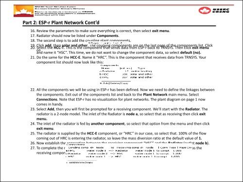
Part 2: <strong>ESP</strong>-r Plant Network <strong>Co</strong>nt’d16. Review the parameters to make sure everything is correct, then select exit menu.17. Radiator should now be listed under <strong>Co</strong>mponents.18. The second step is to add the coupling plant components.19. Click add, then solar <strong>and</strong> other. The coupling components are on the last page of the components list. Click20. Select the HCC-T. This is the component that sends data from <strong>ESP</strong>-r back to <strong>TRNSYS</strong>. Then click exit menuon<strong>and</strong> name it “HSC”. This time, we do not want to change the component data, so select default (no).21. Do the same for the HCC-E. Name it “HRC”. This is the component that receives data from <strong>TRNSYS</strong>. Yourcomponent list should now look like this:22. All the components we will be using in <strong>ESP</strong>-r has been defined. Now we need to define the linkages betweenthe components. Exit out of the components list <strong>and</strong> back to the Plant Network main menu. Select<strong>Co</strong>nnections. Note that <strong>ESP</strong>-r has no visualization for plant networks. The plant diagram on page 1 nowcomes in h<strong>and</strong>y.23. Select Add, then you will first be prompted for a receiving component. We’ll start with the Radiator. Theradiator is a 2-node model. The inlet of the Radiator is node a, so select that as receiving then click exitmenu.24. The inlet of the radiator is fed by another component, so select that option from the menu <strong>and</strong> then clickexit menu.25. The radiator is supplied by the HCC-E component, or “HRC” in our case, so select that. 100% of the flowcoming out of HRC is entering the radiator, so leave the mass diversion ratio at the default value of 1.26. Now establish the connection between the receiving component “HSC” <strong>and</strong> the Radiator (outlet node b).27. To complete the network, the coupling components in the loop must be connected. Set “HRC” as thereceiving component <strong>and</strong> “HSC” as the sending component.