ASSEMBLY INSTRUCTIONS FOR THE ICM - Silent Hektik
ASSEMBLY INSTRUCTIONS FOR THE ICM - Silent Hektik
ASSEMBLY INSTRUCTIONS FOR THE ICM - Silent Hektik
- No tags were found...

Create successful ePaper yourself
Turn your PDF publications into a flip-book with our unique Google optimized e-Paper software.
<strong>ASSEMBLY</strong> <strong>INSTRUCTIONS</strong> <strong>FOR</strong> <strong>THE</strong> <strong>ICM</strong><strong>ASSEMBLY</strong> <strong>INSTRUCTIONS</strong> <strong>FOR</strong> <strong>THE</strong> <strong>ICM</strong><strong>ICM</strong>_E_06(c)1997-2009SILENT HEKTIK Hansastr. 72b 59425 Unna Germany order@silent-hektik.com Fax. (+49) 02303-257071 Page 1
<strong>ASSEMBLY</strong> <strong>INSTRUCTIONS</strong> <strong>FOR</strong> <strong>THE</strong> <strong>ICM</strong>SENSORS:The <strong>ICM</strong>-box is able to work with up to 10 analog inputs. 1.Air-pressure sensor, 2.voltage, 3.CO-potentiometer, 4.throttlepotentiometer,5.left-hand PM-sensor, 6.right-hand RPM sensor, 7.air-temperature, 8.engine-temperature, 9.left-hand Lambdaprobe,10. Right-hand Lambda-probe.The airpressure-sensor, the CO-potentiometer as well as the voltage-reading is located inside the <strong>ICM</strong>-box; no assembly necessary.The throttle-potentiometer is already installed on the right-hand throttle body, so no assembly required either. Both Lambdaprobes are not included in the specifications; an optional assembly is possible.To mount on the vehicle there are only both temperature sensors left as well as in case of Guzzi & BMW the pickup.AIR-TEMPERATURE-SENSOR:The air- and engine-temperature-sensors are identical. The stainless steel case has a M10x1mmthread like the small spark plugs.The air-temperature sensor can be mounted on top or at the back of the airbox. To prevent theairbox from cracking by vibrations the use of a small aluminum-plate with a thread on the innerside of the box is recommended.When using open intakes the sensor should be mounted near the intakes. Mount the sensor to theframe with the biggest distance to engine possible.Ducati 900SS ´93ENGINE-TEMPERATURE-SENSOR:2V-Boxer R100RThe air- and engine-temperature-sensors are identical. The stainless steel case has a M10-1mmthread like the small spark plugs.Guzzi - 1100SportMounting on a Guzzi:Mounting on a BMW:Mounting on a Ducati:Thread in the cooling fins of the Z-head above or next to the inletmanifold,or hole in the valve-coverThread in the cooling fins of the Z-head above or next to the inletmanifoldin the front upper valve-cover of the horizontal cylinderWe do not recommend an installation on or in the oil-pan as it could cause leakage’s due to thelow torque when tightening the sensor.The plus-pole of the temperature sensor is the same as on the injection-jets: see plus-symbolDucati 900M/SS in the finsuseable solution, optical OK2V-Boxer R100RThread in the fins, simple and OKGuzzi 1100 Sport Thread in the finssimple solution but OKSILENT HEKTIK Hansastr. 72b 59425 Unna Germany order@silent-hektik.com Fax. (+49) 02303-257071 Page 3
<strong>ASSEMBLY</strong> <strong>INSTRUCTIONS</strong> <strong>FOR</strong> <strong>THE</strong> <strong>ICM</strong>MAGNETIC POLARIZATION OF <strong>THE</strong> BOSCH ALTERNATOR - GUZZI AND BMW:For a faultless function of the ignition system the south-pole has to be on the sliprings of the Bosch-alternator-rotor. Up tonow that’s been standard on all OEMalternator-rotors. Aftermarket or exchange alternator-rotors are very often poled theopposite way. With a compass the polarization can be checked easily. With the ignitionswitched off the north-pole of the compass is drawed to the rotor by his south-pole.The correct polarization of the alternator-rotor can be achieved by changing the rotoror exchanging the of the alternator carbon brushes. We recommend to use a correctalternator-rotor as the performance of the alternator will increase by that. Byexchanging the carbon-brushes the left-hand brush needs to be insulated like theright-hand one. Original insulation material can be purchased from every specializeddealer. The magnetic polarization of Saprisa-alternators or Ducati-alternators doesn’tneed checking.Compass-north to Bosch alternator-southPICK UP AND ALTERNATOR-ROTOR GUZZI & BMW :The ignition rotor needs to be mounted on the alternator-rotor. Therefore use theoriginal screws. Please check the connecting surface of the rotor and removeeventually excisting grades which can be found through the wearing of the lock-platevery often.The Pickup has to be mounted to the Bosch alternator with the screws of the U-V-Wsocket.At the Saprisa-alternator you are using the original screw with the 5mm spacer;moreover a 5mm thread has to be attached to the alternator.The distance between rotor and pickup should be 0.2-0.3 mm on all wings. The basicmechanical adjustment relates to the static ignition-moment:Guzzi Cali`s & Tourer 4°-6° BTDC Guzzi all LM`s 8° BTDCDucati, all models 6° BTDC BMW all 2V-boxer 6° BTDCPickup on Bosch-altn.- right hand cylinderFor the basic adjustment use the right-hand cylinder and the corresponding ignitionrotor-winglike shown on the picture.The leaving edge of the rotor should be located at the center of the pickup steel-core;The wing is rotating clockwise. To hold the rotor when tightening use the wrench of acutting-off grinder.Check the static ignition timing with a strobe-tool at 1200 rpm & 0%TPS & 90°C. Below980 rpm & > 0%TPS & < 70°C the idle-stabilization is working.The left cylinder doesn’t require any adjustment.IGNITION COILS:Exchange the original coils by the <strong>Silent</strong> <strong>Hektik</strong> coils. In principle powercoils shouldalways be cooled by the riding-air if possible -> mount below the steering head.Under the assumption that the ignition system is working properly the electrode-gapcan amount to 0,5-0,7mm.Please use only interference-free coil- and sparkplug-sockets with a minimumresistance of 5 kW as well as resistor sparkplugs. This fully electronic system will onlywork properly with a very good interference suppression.Only coils with a primary resistance of at least 3 OHM are allowed. -> loss ofguarantee!!! When switching off the engine the power-box of the module will beswitched off after a few seconds. Please remind this fact when working on it!Electronic rev-counters are to be connected to clamp K_1 of the coil.The rev-counter outlet of the box is supplying half of the Rpm`s for some Guzzimodels.Pickup on Saprisa-altern. - right cylinderADJUSTMENT:As a basic adjustment for ALL singlespark-ignitions (standard ignitions) the 34° curvesare coming into question.Coil-installation on a boxer, new frameGuzzi Cali`s & Tourer Nr. A Guzzi all LM`s Nr. EDucati, all models Nr. D BMW all 2V-boxer Nr. CAt engine “ping”, like when using low quality fuel or by running a sidecar please usethe next flater level curve with 34° BTDC. To adjust a Twinspark ignition (twosparkplugs) it needs a lot of experience and sure instinct. We recommend to followthe instructions of the tuner. When adjusting yourself please start with the followingadjustments and try the curves below or above while riding the bike:Up to 90mm and up to a compression ratio of 10:1Up to 90mm and from a compression ratio of 10:1 upwardsNr.6Nr.5At maximum driving-dynamic and smoothest engine-running the adjustment isfinished. With compression over 1:10 you should use radio compressed spark plugs.Coil-installation on Guzzi 1100 SportSILENT HEKTIK Hansastr. 72b 59425 Unna Germany order@silent-hektik.com Fax. (+49) 02303-257071 Page 4
<strong>ASSEMBLY</strong> <strong>INSTRUCTIONS</strong> <strong>FOR</strong> <strong>THE</strong> <strong>ICM</strong>INSTALLATION OF <strong>THE</strong> PICKUPS AND <strong>THE</strong> ROTOR :The ignition rotor needs to be mounted to the crankshaft. Therefore use theoriginal screws. Please check the connecting surface of the rotor and removeeventually excisting grades which can be found through the wearing of the lockplatesvery often.On Ducati belt-engines either the original Kokusan pickup can be usedSensor-plus = yellowOr the supplied <strong>Silent</strong> <strong>Hektik</strong> pickup:Sensor-plus =redsensor-minus=blacksensor-minus=blackThe distance between rotor and pickup should be 0,3-0,6 mm on all wings. Thebasic mechanical adjustment relates to the static ignition-moment of 6°-8° BTDCfor all models = rear picture for the rear/vertical cylinder.For the basic adjustment use the right hand (rear/vertical) cylinder and thecorresponding ignition-rotor-wing like shown on the picture.The leaving edge of the rotor should be located at the center of the pickup steelcore.Please pay attention to the direction of the rotation.Ducati beltdrive right = rear/vertical left = front/horizontalDucati bevel right = rear/vertical left = front/horizontalGuzzi right = right-hand left = left-handCheck the static ignition timing with a strobe-tool at 1200 rpm & 0%TPS & 90°C.Below 980 rpm & > 0%TPS & < 70°C the idle-stabilization is working.The left (front/horizontal) cylinder doesn’t require any adjustment.static ignition timing at the pickupfor the back cylinder (right) at ca. 6°-8° BTDCINSTALLATION OF <strong>THE</strong> COILS:The coils are replacing the original coils. Depending on the model the mountingsupports will fit. When laying the wiring please make sure you to use the biggestdistance between the pickup wiring and the ignitions-cables to prevent anyinterference’s. The coils should be could by the riding wind.The crankcase has to have a very good ground-connection to the battery ->Battery ground wire to crankcase!Under the assumption that the ignition system is working properly the electrodegapcan amount to 0,5-07mm.Please use only interference-free coil- and sparkplug-sockets with a minimumresistance of 5 kW as well as resistor sparkplugs. This fully electronic system willonly work properly with a very good interference suppression; especially incombination with old alternator regulators. Please protect all socket-connectionswith socket-grease against humidity. Never use any battery-pole-grease as this kindof grease is alcalic. Soldered crimp-connections do brake and cause malfunctionsthrough engine vibration. Defective Engine-stop switches mounted on handlebarsand side-stands are very often a source of problems.Only coils with a primary resistance of at least 3 OHM are allowed. -> loss ofguarantee!!! When switching off the engine the power-box of the module will beswitched off after a few seconds. Please remind this fact when working on it!Older rev-counters can be connected to the grey output of the box. Newer revcounterscan be connected to the coil socket KL1-. The box won’t be destroyed bytrying out.static timing 6°-8° BTDCall modells - singel- & twin-sparkCheck the static timing at 1200 RPM for the backcylinder with a timing light through the window( for racing-cams MIDDLE screw-head )ADJUSTMENT:As a basic adjustment for ALL singlespark-ignitions (standard ignitions) the 34°curves are coming into question.All Tourer, Comp. Ratio 1:9 Nr. EAt engine “ping”, like when using low quality fuel or by running a sidecar pleaseuse the next flater level curve with 34° BTDC. To adjust a Twinspark ignition (twosparkplugs) it needs a lot of experience and sure instinct. We recommend tofollow the instructions of the tuner. When adjusting yourself please start with thefollowing adjustments and try the curves below or above while riding the bike:Up to 90mm and up to a compression ratio of 10:1 Nr. 6Up to 90mm and from a compression ratio of 10:1 upwards Nr. 5from 92mm and up to a compression ratio of 10:1 Nr. 2from 92mm and from a compression ratio of 10:1 upwards Nr. 2At maximum driving-dynamic and smoothest engine-running the adjustment isfinished. From compressions ratios of 10:1 upwards interference-free sparkplugshave to be used.Coil-installation on frame for air-coolingSILENT HEKTIK Hansastr. 72b 59425 Unna Germany order@silent-hektik.com Fax. (+49) 02303-257071 Page 5
<strong>ASSEMBLY</strong> <strong>INSTRUCTIONS</strong> <strong>FOR</strong> <strong>THE</strong> <strong>ICM</strong><strong>THE</strong> INTAKE CHANNEL:The intakes of both cylinders have tobe enlarged around 4mm out of thecenter and tapered adapted to themounting distance on a length ofabout 40 – 50mm. By this chance theports around the valve guides can bewidened on both sides around 1-2mm.For the installation of the intake partsthe paper gaskets should be fittedwith a bit of Hylomar.The 944cc cylinders have to beinstalled as per the Ducati workshopmanual.At the 900M the engine can remain inthe frame; at the 900SS the engine hasto be removed.It is a lot easier if the piston isinstalled in the cylinder on a benchfirst before connecting it to theconrod.Neither cylinder nor pistons should berubbed with oil or grease; the factorycoating is perfect for the first run in.Inside the combustion chamber theedges of the squeeze-edge should bemodified to a 2mm radius.<strong>THE</strong> INTAKE FUNNELS:Both funnels had been computerdesignedespecially for the Ducatiengine. Even though they are quitelong a maximum RPM of 11.000 RPM ispossible.At the 900SS both funnels lead intothe original airbox-holes. No furthermodifications are required.At the 900M the left body has to bemounted below a crosswise strut andtherefore a new hole for the funnel isrequired.This hole can be cut into the plastic ofthe airbox by using a sharp knife or afine saw blade.Due to the curve of the funnel an ovalhole is required; the funnel mighttouch the inner side of the airbox andtherefore might need to be adapted afew millimeters (see right-handpicture)80R35535105SILENT HEKTIK Hansastr. 72b 59425 Unna Germany order@silent-hektik.com Fax. (+49) 02303-257071 Page 6
<strong>ASSEMBLY</strong> <strong>INSTRUCTIONS</strong> <strong>FOR</strong> <strong>THE</strong> <strong>ICM</strong>BEVEL-DRIVE:At bevel drive engines the originalintake funnels can be used. Payattention to the flame-sieves to avoidunpleasant hot calfs.<strong>THE</strong> PUMP-BLOCK:At the 944ie kit the pump-block has tobe mounted to the back of the airboxwith 4 screws, in direction to theBattery.900 M/SS BELT DRIVE:The 944ie kit is perfectly designed forthe use on a 900SS. The intake funnelsfit right into the airbox. -> see rightAt the Monster-models you have tocreate a hole as a crosswise strut ofthe frame is in the way of the rear/standing cylinder. For use incompetition this strut should bemoved to achieve an optimum for theintake-system.PS100STOCK - MANIFOLDSFor the 900 SS & Monster belt-drivemodels we also sell 42mm bodys forthe stock-manifolds.The original rubber-parts are usedwith it.9080706050900M Serie944ie944SS MikuniNm100The pump-block finds a place on thefrond side of the air-box.408060404ooo6ooo8ooo10oooU/minDIN-PER<strong>FOR</strong>MANCE:red = <strong>ICM</strong> mit 944ccm 95 HPgray = Mikuni mit 944ccm 84 HPblue = Serie mit 904ccm 73 HPSILENT HEKTIK Hansastr. 72b 59425 Unna Germany order@silent-hektik.com Fax. (+49) 02303-257071 Page 7
<strong>ASSEMBLY</strong> <strong>INSTRUCTIONS</strong> <strong>FOR</strong> <strong>THE</strong> <strong>ICM</strong><strong>THE</strong> THROTTLE BODIES AND <strong>THE</strong> JETS:The throttle bodies are replacing the carburetors and are to be mounted to the standard intakes. For the pivot of the throttlebodies on BMW the standard throttle cables as well as the original throttle-handle for the 40´ Bing carbs can be used. For Ducatiand Guzzi you`ll need to install a Tommaselli throttle-handle in combination with LM1 throttle cables. The cables should have aback lash of about 1mm.The adjustment of the idle as well as the synchronization of the throttle valves have to be done via the block-screws on the inside.The procedure is quite the same as in case of carburetors. Engine-revs via throttle block-screws, air-fuel-mixture via map-figures ofthe <strong>ICM</strong>-monitor. The adjustment with the maximum rev`s of the engine when idling is the correct adjustment. The idle should bebetween 1050 and 1100 RPM with the engine at normal operating temperature. When the adjustment is finished, the <strong>ICM</strong>-boxshould be switched off and on once to save all parameters.BMW 2Ventil-Boxer 40er Bing replacement Ducati beltdrive 38er Mikuni replacement Guzzi Big-Block 40er DellOrto replacementOn the right-hand throttle body you`ll find the throttle-potentiometer. This sensor is recording the angle of the throttle valvesand assigning it to the corresponding load of the engine.On the jet-brackets you`ll find two hose-connections for the fuel-lines. One line is the fuel feeding, the other one is the return. Itdoesn’t matter which one of the connections you are using what for. Please pay attention to push the stiff pressure-hoses up tothe end of the connection and to tighten the cap-nuts up to the block.Via the feeding- and the return-lines the injection jets are permanently rinsed with fuel and together with the very thin pressurelinesa very high flow-speed is achieved, which is carrying gas-bubbles away and cooling down the injection jets.On our throttle bodies we are using 4 different types of jet-technologies. The choice depends on the specific vehicle the system isgoing to be used for: standard, medium and pico.For the synchronization of the throttle bodies you HAVE to use vacuum gauges. With the sparkplug-socket pulled off parts of theelectronics can be harmed, even if this can’t be recognized immediately.The arrangement of the jets guaranteesan optimum air-fuel-mixture as the fueljet is heading directly into the gap ofthe throttle valve, where the gasflow isat the maximum speed.It has been applied for a patent for thisnovel procedure.2VBoxer Cafe-RacerGuzzi 1100STest of the injection-volume at 1,3 bar system-pressure, 12V and 20°C:Size color fuel-volume————————————————————————–———————————Standard white 17ml ^ 6,2 Ltr/hStandard beige 35ml ^ 12,6 Ltr/hMedium grey 36ml ^ 13,1 Ltr/hMedium green 32ml ^ 11,5 Ltr/hMedium black 21ml ^ 7,6 Ltr/hPico türkis 16ml ^ 5,8 Ltr/hPico orange 20ml ^ 7,3 Ltr/hSILENT HEKTIK Hansastr. 72b 59425 Unna Germany order@silent-hektik.com Fax. (+49) 02303-257071 Page 8
<strong>ASSEMBLY</strong> <strong>INSTRUCTIONS</strong> <strong>FOR</strong> <strong>THE</strong> <strong>ICM</strong><strong>THE</strong> PUMP-BLOCK:The feeding of the pump-block is located on the pump side,as shown on the right hand picture. The fuel needs to befiltered to avoid plugging of the jets. Use only metal-filtersas the suction-volume of the pump would cause the dirt tobreak through paper or plastic filters. To avoid air-lock upsplease mount the filter vertical right after the fuel cock.For the return-line please use the 6mm connection of thepressure regulator as shown on the left side of the picture.The 4mm vacuum-connection in the center remains openPlease pay attention to short and unfolded hoseconnections.Please use rubber- or silicon-hoses with aninner diameter of 6mm and a material-thickness of 1,5 to2mm.Minus on the pump; at the top of the picture – M5 nutPlus on the pump; in the button of the picture – M4 nutThe 4mm tube next to the connections is not in useSecure all hoses on its connector against slipping off with acable tie. The hose-system is self bleeding. Never let thepumpblock run dry!The pumpblock is operating with a system pressure of 1,3bar and a current consumption of 2,5A at 12,5V. Each hour120 / 140 Liter fuel are circulating.On the pressure-side the feeding- as well as the return-linehave to be mounted by using the blue cap nuts. Please payattention to push the stiff pressure-hoses up to the end ofthe connection and to tighten the cap-nuts up to the block.The pumpblock can be mounted horizontal or vertical, butnever direct next to heat-emitting parts like the exhaust orcylinderheads as this might cause gas-bubbles.Pumpblock on a Ducati 900M/SS – belt driveA cooler location guarantees safe operations under hotcircumstances (like stop and go traffic) and supports thelifetime of all parts.To minimize the noise of the pumpblock you can mount iton silent-blocks.With the engine switched off the pump shuts off afterabout 10 seconds.If possible the pumpblock should be mounted below thelevel of the fuel tank. When mounting it above the level ofthe fuel tank a maximum height of 30 cm shouldn’t beexceeded.On feedings longer than 1m a check valve needs to beinstalled right next to the tank.Pumpblock on a Boxer R100RThe pumpblock can be used with any kind of pump gas,leaded or unleaded, mixed or with alcohol.Using additional aggressive additives can reduce thelifetime of the system dramatically.Pumpblock on a Guzzi 1100 Sport10mm out of the centerSILENT HEKTIK Hansastr. 72b 59425 Unna Germany order@silent-hektik.com Fax. (+49) 02303-257071 Page 9
<strong>ASSEMBLY</strong> <strong>INSTRUCTIONS</strong> <strong>FOR</strong> <strong>THE</strong> <strong>ICM</strong><strong>THE</strong> <strong>ICM</strong>-BOX:The <strong>ICM</strong>-box is the heart of the system. Here all sensors and actorsare connected to.On the front side you’ll find the 25 pole socket as well as the COpotentiometer(anti-clockwise is richer) left to it.On the back side you’ll find the Sub-D for the connection to the PC.As mounting location we do prefer the frame-triangle below theseat. The <strong>ICM</strong>-box should be somehow protected against water.The feeding to the 25 pole socket should be handled very carefully:free of any mechanical excitement and protected against vibrationand scrubbing with an Insulation-tube.First you should determine all cable length to then lay theinsulation tube. From there it goes to the single sensors andconsumers.<strong>ICM</strong> Box on a Ducati 900M with standard airbox andsmall Hawker-battery. Ignition-coils are mounted tothe frame.Mounting the <strong>ICM</strong> under the seat is more useful.<strong>ICM</strong>-box in the tool-box of a Boxer<strong>ICM</strong>-box under the seat of a Guzzi 1100 SportThe wiring harness should be laid from the <strong>ICM</strong>-box to the single components.Care and a very good crimp-pliers are the basic assumptions.SILENT HEKTIK Hansastr. 72b 59425 Unna Germany order@silent-hektik.com Fax. (+49) 02303-257071 Page 10
<strong>ASSEMBLY</strong> <strong>INSTRUCTIONS</strong> <strong>FOR</strong> <strong>THE</strong> <strong>ICM</strong>4D - Kennfeld Umschaltung für <strong>ICM</strong> 11-2006Index F E D C B A 9 8 7 6 5 4 3 2 1 0Last 0 2 4 7 11 16 22 28 34 40 47 54 60 67 73 80%Offset 8 8 8 8 8 8 8 8 7 6 5 4 3 2 1 0°————————————————————————————————————————————————————————————————150°C 20 20 20 20 20 20 20 20 19 18 17 16 15 14 13 12°140°C 22 22 22 22 22 22 22 22 21 20 19 18 17 16 15 14°Schalter0 22 22 22 22 22 22 22 22 21 20 19 18 17 16 15 14°vOT123 23 23 2324 24 24 2423 23 23 2324 24 24 2423 21 20 1923 22 21 2018 17 16 15°19 18 17 16°25 25 25 25 25 25 25 25 24 23 22 21 20 19 18 17°2 26 26 26 2627 27 27 2726 26 26 2627 27 27 2725 24 23 2226 25 24 2321 20 19 18°22 21 20 19°3 28 28 28 28 28 28 28 28 27 26 25 24 23 22 21 20°4529 29 29 2930 30 30 3029 29 29 2930 30 30 3028 27 26 2529 28 27 2624 23 22 21°25 24 23 22°6 31 31 31 31 31 31 31 31 30 29 28 27 26 25 24 23°7 32 32 32 3233 33 33 3332 32 32 3233 33 33 3331 30 29 2832 31 30 2927 26 25 24°28 27 26 25°8 34 34 34 34 34 34 34 34 33 32 31 30 29 28 27 26°935 35 35 3536 36 36 3635 35 35 3536 36 36 3634 33 32 3135 34 33 3230 29 28 27°31 30 29 28°37 37 37 37 37 37 37 37 36 35 34 33 32 31 30 29°A 38 38 38 3839 39 39 3938 38 38 3839 39 39 3937 36 35 3438 37 36 3533 32 31 30°34 33 32 31°B 40 40 40 40 40 40 40 40 39 38 37 36 35 34 33 32°C41 41 41 4142 42 42 4241 41 41 4142 42 42 4240 39 38 3741 40 39 3836 35 34 33°37 36 35 34°43 43 43 43 43 43 43 43 42 41 40 39 38 37 36 35°D 44 44 44 4445 45 45 4544 44 44 4445 45 45 4543 42 41 4044 43 42 4139 38 37 36°40 39 38 37°E 46 46 46 46 46 46 46 46 45 44 43 42 41 40 39 38°F47 47 47 4748 48 48 4847 47 47 4748 48 48 4846 45 44 4347 46 45 4442 41 40 39°43 42 41 40°vOT————————————————————————————————————————————————————————————————Grafik zeigt die Zündkurven Schalter A, 9, 8, 7ab 80% Last°vOT30°28°26°24°5°rpmStat. ZZP = 5°vOT für alle Kurven + Felder als Bezugsgröße für DatenDie Auswahl des Zündkennfeldes bezieht sich auf den max. Zündwinkelab 80% Drosselklappe. Abweichende stat. Zündwinkel werden dazu addiertbzw. subtrahiert:zB. Guzzi LM2 = 33° bei 8°stat. = A (30° bei 5°stat.)zB. Guzzi Cal2 = 33° bei 2°stat. = D (36° bei 5°stat.)SILENT HEKTIK Hansastr. 72b 59425 Unna Germany order@silent-hektik.com Fax. (+49) 02303-257071 Page 11
<strong>ASSEMBLY</strong> <strong>INSTRUCTIONS</strong> <strong>FOR</strong> <strong>THE</strong> <strong>ICM</strong>FIRST STEPS :MECHANISM:After switching on the power supply the fuel pump starts running for a few seconds to bleed the system. To support the processof ventilation one pressure-return should not be connected to the body in the first stage, but somehow connected to a fuelresistant container. As soon as any air is removed out of the pumpblock the pressure hose can be connected again. The system isgoing to be bleeded whenever it is going to be switched on. Please pay attention to any folds of the pressure hoses.The throttle bodies should first remain open about 1,5 turns and later on fine-adjusted to about 1000 RPM.SENSORS:By switching on the power supply the <strong>ICM</strong>-box is testing all sensors and calculating the zero-level of the potentiometers. Due tothis NEVER operate the throttle while switching on the unit!With the monitor-program in online-mode (F3) all components can be checked quickly. In case of malfunctioning you can use thediagnosis-mode to solve the problem.START & IDLING:Start the warm engine WITHOUT operating the throttle. At engine temperature below 40°C you should open the additional airslideson the bodies (in the future they can be operated electrical). Eventually open the throttle about 4%-8% to place a bit moreair to the engines disposal at the beginning.The acceleration pump is also working without the engine running. Due to this the air-fuel mixture can be enriched beforestarting: ACSQ. ATTENTION: If used to often the engine can be “drowned”.>1,5 kRPM and > 0% throttle the dynamic acceleration-enrichment will be adjusted: ACDQ. For starting the engine the data 250are to be adjusted. To adjust the idling without a PC the CO-Poti can be used = anti-clockwise rotation make the mixer richer.For starting a cold engine the MOTOR-TEMP (MTS) figures are to be adjusted to enrich the air-fuel mixture. At extremetemperatures a cold-start-adjustment in addition to the mass-compensation can be created: LUFT-TEMP ATS (AIR-TEMP).Idling with more than 1,0 kRPM the FUEL-MAP figures have to be adjusted. The idle should first be adjusted to 5% - 6% CO orbetter at about 0,86La to 0,88La (Lambda) at engine on operating temperature. This figure will be registered in 750 - 1000 - 1200.Then FUEL-MAP will have to be adjusted again to 3-4% CO (0,92La – 0,95La).Above 1,5 kRPM and above 0% throttle the thrust-disconnection can be adjusted to save fuel. On 0 the thrust disconnection isswitched off. If the figures are to high the fuel-film will be reduced: the engine starts stuttering and accelerates with delay.The figures below 1,5 kRPM but over 0% throttle are for starting to drive and should be a bit richer (0,84La).Should the single cylinders require different fuel-volume when idling the figures LeOF and RiOF should be adjusted. At >1,5 kRPMthe dynamic offset LiOF and NLOF are necessary to calibrate the map and the injection valve to the engine horsepower.<strong>THE</strong> FUEL-MAP:The fuel volume for your engine depends on the power curve and the wanted adjustment: Figures above 1,5 kRPM (from bottomto the top) and >0% throttle (from left to right).AREA OF OPERATIONS:1) idle enriched a bit2) theoretical working areaat constant accelerationand low load, independent from load and gear3) start-area at stop & gotraffic, enriched a bit4) Full acceleration like onan acceleration-dyno orwhen trying to overtake;strongly enriched5) Pushing like runningdown a hill or in front ofa traffic light, stronglyleaned61532746) Engine RPM x 10007) Throttle valve in percent<strong>THE</strong>ORY:An Otto-engine needs per HP and hour about 250 grams fuel (330ml) to reach the full potential. The maximum performance of anOtto-engine will be reached at about 0,88La to 0,9La (slightly enriched)The lowest fuel consumption can be reached at about 1,1La. As this is extremely lean the engine starts stuttering under load anddue to this it makes only sense under pushing operation.For acceleration the mixture has to be enriched to 0,78La – 0,84La to reach maximum acceleration.At Lambda 1 the engine has the lowest emission but also the lower performance at increased fuel consumption and higher enginetemperature.At figures below 0,7La (very rich) or above 1,2La (very lean) the limit for ignition is reached, the engine starts stuttering.SILENT HEKTIK Hansastr. 72b 59425 Unna Germany order@silent-hektik.com Fax. (+49) 02303-257071 Page 12
<strong>ASSEMBLY</strong> <strong>INSTRUCTIONS</strong> <strong>FOR</strong> <strong>THE</strong> <strong>ICM</strong>TUNING:The tuning in practical use is the only really complicated section of the <strong>ICM</strong>-kit.During the dynamic of driving all figures of the injection-screen are meshing. Ittakes a lot of experience as well as time not to mix up cause and symptom.With a little time and a Lambda sensor as a measuring tool a good tuning can bereached by any dedicated user.<strong>THE</strong> BEGINNING:First 2% to 17% throttle should be adjusted on the engine (at normal operatingtemperature). It should be either 6% to 8% or better 0,88La to 0,9La.If the figures under FUEL-MAP should go down to zero air-pressure andtemperature-figures have to be decreased.With load (while starting) the figures might vary a bit, usually they have to beenriched.Also full-throttle adjustment is possible on the highway or on a dyno. At nominalpower about 0,88La to 0,9La should be adjusted.<strong>THE</strong> DRIVING AREA:The range from 10% to 60% throttle should be adjusted with a Lambda sensorwhile driving. This area is the one which is depending the most on the engineconceptas well as on the driving habits. Most of the motorbike riders arerunning their engines within this area.The tune up can be varied from super-dynamic (high fuel-consumption) down toa bit indolent and tired (low fuel consumption).The full throttle adjustments can be done onthe dyno or on the highway.The fuel-saving circuits have to be shut off forthese measurements.All figures should be saved regularly while working on the adjustment, so if atune up is wrong you can easily get back to an older but maybe better mapping.Here at <strong>Silent</strong> <strong>Hektik</strong> the following method is used:G_M0520A Guzzi – Müller – may – 20 th – A-version (1 st )D_K0317D Ducati – Kurpas – march – 17 th – D-version (4 th )B_U0403F Boxer – Uwe – april – 3 rd – F-version (6 th )With a little patience and time you’ll find your own individual adjustment at ansatisfying fuel consumption.<strong>THE</strong> THRUST-DISCONNECTION:To safe fuel we are using a thrust disconnection. Under FCOQ the quantity of thefuel-volume you want to reduce the total volume about can be adjusted:0/1=off 2= -3,2% 3= -6,5% 4=-12% 5=-25% 6=37% 7=-50%With FCOD the quantity (the duration) of the fuel-saving can be adjusted;depending on the bike-model and the individual driving habits an adjustmentbetween 10 and 50 is useful.Another ”saving-circuit” is the constant-ride-emaciation CDFQ + CDFD. Runningthe engine with constant RPM and throttle-position over an extended period theair-fuel-mixture is to be leaned a bit.0= off 1= -6,25% 2= -12,5% 3= -12,5% but without full throttle<strong>FOR</strong> EMISSION-CONTROL <strong>THE</strong> SAVE CIRCUITS SAM AND KFA NEEDS TO BEADJUSTED TO ZERO TO AVOID ANY DISTORTION OF <strong>THE</strong> READING.P = Performanceb = fuel consumptionLa = LambdaLambda-tension of the Denso probeSILENT HEKTIK Hansastr. 72b 59425 Unna Germany order@silent-hektik.com Fax. (+49) 02303-257071 Page 13
<strong>ASSEMBLY</strong> <strong>INSTRUCTIONS</strong> <strong>FOR</strong> <strong>THE</strong> <strong>ICM</strong>The D_<strong>ICM</strong> system on a 912It is possible to mount the <strong>ICM</strong> (single system) or the D_<strong>ICM</strong> (double system) at an engine with 80hp or 100hp. The ignition demandof both engines is identical. The demand of fuel depends on the power and also on the intake manifold and exhaust pipes ofeach plane. The PC-monitor software makes a fast and precise adjustment to all constellations possible.For a season independent running of the 912 power unit we recommend the application of a water thermostat. The watertemperature should be beetween 70°C and 80°C ( 90°C to 100°C head temperature) , the oel temperature beetween 90°C and95°C to reach an optimum of efficiency and maximum lifetime.The engine should not be heavy loaded beneath 60 °C, this wears it out badly!For a safe start of the 80HP and 100HP engine we recommend the new strong electrostarter with a 12V 16Ah high qualitybatterie. Pay attention for the start-procedur on page 12.The Twin_<strong>ICM</strong> partsThe both Bing carburators with rubbers, the complete CDI ignition with the pickups and the mechanical fuelpump will beremoved from the engine. The tube between the two manyfolds and the manyfolds itselfe are in use. For syncronisationof the two inlets please use the smal vaccum connectors on the trottlebodys. The right mixture at idling is about 4%carbonmonoxid or 0,85 LambdaThe air temperature sensors must have contact the incomming air but not to the warm engine or it warm parts. Oncomposite airboxer are no problems. On aluminium airboxes an isolation is requirt. On textiles airfilters the sensor can bemounted on the rubber backside of the filters.SILENT HEKTIK Hansastr. 72b 59425 Unna Germany order@silent-hektik.com Fax. (+49) 02303-257071 Page 14
<strong>ASSEMBLY</strong> <strong>INSTRUCTIONS</strong> <strong>FOR</strong> <strong>THE</strong> <strong>ICM</strong>The trigger-rotor with pickupsTo measure the position of the crankshaft, a rotor has to be mount on the dynamos flywheel. Four of the finger stand in anangle of 90° to each other. The Sync-Finger has an angle of 22,5°. To fix the rotor in the right angle to the crankshaft, a M8 bolthas to be screwed in front of the aluminium case. The bolt blocks the crankshaft and the crankshaft screw can be un– ortightened with 120Nm. The original triggerrotor must be maschined to a round shape of about 144,5mm diameter. Both triggernosesmust be completly remove. The two cylinder in the front are located in the top dead center. The distance of the twopickups should be equal and amount to 0,4mm- 0,6mm. The ten screws and distances are of nonmagnetic material. Thealuminium baseplate has to be screwed onto the engine with three 20mm spacer.weiß-gelb / white-yellow ( schwarz / black )= Minusblau-gelb / blue-yellow ( rot / red ) = PlusThe alternator output for the CDI ignitions are not inuse. Please isolate and tightened it.SILENT HEKTIK Hansastr. 72b 59425 Unna Germany order@silent-hektik.com Fax. (+49) 02303-257071 Page 15
<strong>ASSEMBLY</strong> <strong>INSTRUCTIONS</strong> <strong>FOR</strong> <strong>THE</strong> <strong>ICM</strong>BodysReglerTank
<strong>ASSEMBLY</strong> <strong>INSTRUCTIONS</strong> <strong>FOR</strong> <strong>THE</strong> <strong>ICM</strong>The IntakeTo get the best adjustment possible for each type of aircraft, the original intake manifold is still used. It is very flat andthat is why there is no need to change something at the cowling. The carburettor with a carburator flange is no morerequired. Instead the body is assembled directly. Please pay attention to an excellent sealing to secure a solid idling. Theintake manifold is available in a diameter of 50mm, 60mm and 72mm. The 50mm version is the best standard solution.The injection jet holder has to be mounted between the cylinder head and the intake manifold. Again please payattention to a good sealing on account of the idling. The ignition cables should have the greatest possible distance to themotor temperature sensor and the throttle position sensor. There are two vacuum supplies for the syncronisation of thethrottle and two bypass-channels with an screw for the micrometer adjustment.The Motor-Temp.-SensorThe Motor-Temp.-Sensor should be locatedon backwards valvecover. Therefore aM10x1mm thred must be mashined and thesensor srewed and glued in it.SILENT HEKTIK Hansastr. 72b 59425 Unna Germany order@silent-hektik.com Fax. (+49) 02303-257071 Page 17
<strong>ASSEMBLY</strong> <strong>INSTRUCTIONS</strong> <strong>FOR</strong> <strong>THE</strong> <strong>ICM</strong>The ignition coilsThe four ignition coils can be placed in their original position. As a matter of principle the ignition cables should be as short aspossible and in a maximum distance to the sensor cables. The other, better position of the coil is in front of the engine. In thiscase the high tension cable are short as possible.The high tension leeds must be istalled in the best way and cut to theright length. Before crimping the connectors the U-wire must be placedto the end. The wire connencts the stainless steel core with theconnector.Lambda - MeasurementFor an adjustment of the different 912 configurations, a Lambda-measuring method is used. It is useful to measure at two differentcylinders, e.g. on the left in front and on the right at the back. Different exhaust systems are causing mostly different fillings, whichneed to be adjusted to the different fuel amount. An optimum would be four equal fillings, which can only be achieved with a 4-in-1tuned exhaust pipe.For a load from 0% up to 33% we recommend a Lambda from 0,94La up to 0,98La. For a load from 33% up to 70% we recommend aLambda between 0,90La – 0,94La. For the two highest loads (full throttle) we recommend a Lambda from 0,85La up to 0,88La.SILENT HEKTIK Hansastr. 72b 59425 Unna Germany order@silent-hektik.com Fax. (+49) 02303-257071 Page 18
<strong>ASSEMBLY</strong> <strong>INSTRUCTIONS</strong> <strong>FOR</strong> <strong>THE</strong> <strong>ICM</strong><strong>ICM</strong>_AMainLambda-Sonden:Denso blau + weiß -NGK schwarz + grau -321 6 45(optional)(optional)12V16AhBatterieMain switch(optional)Motor-TAir-TAirvalve212113-+12-+12-+12<strong>ICM</strong>_BBackupSILENT HEKTIKD-<strong>ICM</strong> Schaltplan6. Version30.01.2012TPS1412513121231121212+-Motor-T+-Air-T+-AirvalveLambda-S.10A10ATPSCoil-+Injector+Injector-+-+-+-Motor-Injector+-+Injector-+-+Pump_BBackup-+1412513CoilCoilCoilPump_A2 143The wiring diagram for the D_<strong>ICM</strong>. Two <strong>ICM</strong>´s work redundand and can be tested indepandently with the schwiches.The pin configuration and colors of the connectors are in the diagramm on page 23.SILENT HEKTIK Hansastr. 72b 59425 Unna Germany order@silent-hektik.com Fax. (+49) 02303-257071 Page 19
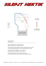
<strong>ASSEMBLY</strong> <strong>INSTRUCTIONS</strong> <strong>FOR</strong> <strong>THE</strong> <strong>ICM</strong>fuel cock fuel cocktwo-fuel cock-versionfine-filterfine-filterpump blocktwin-cylinder-versionthrottle bodythrottle bodyCaution fuel !Risk of fire and poisoning !Hose connection for the return hoseeventually equipped with a return-valvefuel cocksingle-fuel cock-versionfine-filterfine-filterpump blocksingle cylinder versionthrottle bodySILENT HEKTIKHydraulic <strong>ICM</strong>_05M5. VersuchM 24.10.2001SILENT HEKTIK Hansastr. 72b 59425 Unna Germany order@silent-hektik.com Fax. (+49) 02303-257071 Page 20
<strong>ASSEMBLY</strong> <strong>INSTRUCTIONS</strong> <strong>FOR</strong> <strong>THE</strong> <strong>ICM</strong>16A Sicherung Zündschloßschwarzschwarz<strong>ICM</strong>_Box 06ACO - Poti+ --rotblau1425113weißDenso-La.Denso-La.blauweißLuftventil - PlusLuftventil - Minusoptionalblau12VBatterieMinus an Motorblock1,0 qmm1,5 qmmweiß 1blau 2braun 1VORSICHT Hochspannung, Gefahr !Ein Pickup-Version auf linken Kanalrotschwarzrotgrünrotbraunrotgelbrotgrün-gelbMotor-TLuft-T12122.Düse +2.Düse -2.Düse +2.Düse -schwarzDrossel-PotiE-VentilE-VentilrotSILENT HEKTIKZündspuleZündspuleBenzin-PumperotschwarzPickupPickup13Anschlußplan <strong>ICM</strong>_07RechterLinkerRechterLinkerRechtsLinkerM10. VersionM 24.10.2002Kanal Kanal Kanal Kanal KanalblaugraurotFarben rot blau gelb grün braun schwarz grau weiß grün-gelb Links RechtsColors red bleu yellow green braun black grey white green-yellow left rightblau2SILENT HEKTIK Hansastr. 72b 59425 Unna Germany order@silent-hektik.com Fax. (+49) 02303-257071 Page 21
<strong>ASSEMBLY</strong> <strong>INSTRUCTIONS</strong> <strong>FOR</strong> <strong>THE</strong> <strong>ICM</strong>ADRESSE ::::TEL-NUMBER :FAX-NUMBER :HOMEPAGE :SHIPPING :SILENT HEKTIKHANSASTR. 72BD-59425 UNNAGERMANY+49-2303-257070+49-2303-257071WWW.SILENT-HEKTIK.COMWORLDWIDEMember of:SILENT HEKTIK Hansastr. 72b 59425 Unna Germany order@silent-hektik.com Fax. (+49) 02303-257071 Page 22