assembly instructions for bosch and motoplat ... - Silent Hektik
assembly instructions for bosch and motoplat ... - Silent Hektik
assembly instructions for bosch and motoplat ... - Silent Hektik
- No tags were found...

You also want an ePaper? Increase the reach of your titles
YUMPU automatically turns print PDFs into web optimized ePapers that Google loves.
ASSEMBLY INSTRUCTIONS FOR BOSCH AND MOTOPLAT REPLACEMENTE_D_HKZ_05(c)07_2010SILENT HEKTIK Hansastr. 72b 59425 Unna Germany T. (+49) 02303-257070 F. (+49) 02303-257071 www.SILENT-HEKTIK.com Page 1 of 6
ASSEMBLY INSTRUCTIONS FOR BOSCH AND MOTOPLAT REPLACEMENT :The Power Block ignition system is far superior to conventional ignitions that usually achieve double the ignition tension, double theignition energy, as well as double the spark duration. The adjustment of the ignition timing is worked out by a digital High SpeedMicroprocessor, with 16bit resoloution (65536 points) <strong>for</strong> each single revolution. The Signal conditioning as well as the ignition ampscontrol are also carried out digitally, to achieve maximum efficiency with a minimum loss. The necessary D-Well time of the ignitioncoils is worked out digitally to achieve maximum energy saving. The output requirements of the ignition system (module + ignitioncoil) is approximately 17W with 1000 RPM <strong>and</strong> approximately 67W with 5000 RPM.The full per<strong>for</strong>mance of our Power Block ignitions is only possible with SILENT HEKTIK ignition coils, becausethe ignition curves <strong>for</strong> the relevant ignition energy as well as tensions are tuned <strong>and</strong> the D-Well timing on thetechnical details of the coils are cut.With unsuitable or inadequate ignition coils, not only does the gaurantee expire , there will also be bad trottleresponce; bad coldstart or perhaps missfire.SAFETY PRECAUTIONS AND NOTICESCaution High Tension! Mortal danger !To avoid injury or destruction of the electronic, attention should be paid to the following whenworking on vehichles with full electronic digital high energy ignition systems:- Read the <strong>assembly</strong> <strong>instructions</strong> carefully <strong>and</strong> completely <strong>and</strong> follow the <strong>instructions</strong>.Display warning labels in a good visible place!- To install the modules, specialized knowledge <strong>and</strong> tools are required.- People with a Pacemaker should not carry out work on electronic ignition systems.- To synchronize the carburettor never pull out a spark plug.- Do not touch or remove ignition cable when the ignition is on.- Only connect of disconnect the cable from the ignition system when the ignition isturned off.- Always connect the high tension cable to ground (mass) with or without the sparkplugs after removal.- Checking the function of the high tension part with a spark to the ground (mass) leadsto damage.- Washing the engine or vehichle is only to be carried out when the ignition is turned off<strong>and</strong> the engine is stopped.- The ignition module should be carefully protected from static tension.- Seperate ignition module from the cable harness when electric welding.- Faulty alternator regulators (max. tension 15V ) are often the cause of breakdown.- Jumpstarting with a battery charger is only permitted <strong>for</strong> 1 minute with max. 15V.- There is no gaurantee <strong>for</strong> the accuracy of the timing curves with tuned engines;consultation <strong>and</strong> tuning of the tuner absolutely necessary.- Gaurantee-, replacement or claim <strong>for</strong> compensation only in reference to the suppliedelectronic; mistakes <strong>and</strong> changes in future to be accepted.IGNITION LINES CHOICE FROM THE SWITCH IN THE IGNITION BOX:SILENT HEKTIK Hansastr. 72b 59425 Unna Germany T. (+49) 02303-257070 F. (+49) 02303-257071 www.SILENT-HEKTIK.com Page 2 of 6
ASSEMBLY AND CONNECTIONS:Our digital ignition box is mounted on the original place with the connectionsunderneath <strong>and</strong> replaces both Kokusan ignition boxes. For securing you can use <strong>for</strong>example an O ring.The two original sensor plugs as well as the two cable harnesses are pluggedtogether into the Power ignition box.Take care that the sensor with the ignition coil <strong>for</strong> the horizontal cylinder is pluggedinto the LEFT connection of the digital ignition box <strong>and</strong> the sensor with the ignitioncoil <strong>for</strong> the vertical cylinder is plugged into the RIGHT connection of the digital ignitionbox.The ignition coils are assembled in place of the original ignition coils. The holdersare suitable.The Power ignition cable as well as the Plus <strong>and</strong> Minus cable should be connected tothe ignition coils be<strong>for</strong>e you assemble these, because after the <strong>assembly</strong> it will bevery tight under the coils. You can use the 6.3mm FastOn <strong>for</strong> the 4.8mm connectorof the Minus connection or better reduce the connenctor of the ignition coil with ametal shears sideways to 4.8mm.To avoid faults, take care when laying the cables that the biggest possible distance isbetween the sensor <strong>and</strong> ignition coils supplies. Particularly the ignition coil, shouldbe as far as possible from the Pickup cable.The engine housing must have a good ground (mass) connection to the battery ->Battery ground (mass) cable on gearbox housing!With an optimal working ignition system the amount of the spark plug gap is 0.5 -0.6mm.Please use radio supressed ignition coil connectors with a resistance of minimum 5k<strong>and</strong> / or resistance ignition cable -> otherwise faulty function.The operation of this full electronic device will only be perfect with a good radiosupression.To avoid short circuit with Twinspark applications, be careful that there is enoughdistance <strong>for</strong>m the spark plug socket to the cooling fin. Protect all plug connectorsfrom damp <strong>and</strong> humidity with a special grease.During motor vibration, soldered crimp connectors lead to hairline cracks <strong>and</strong>breakdown.Faulty kill switches on the h<strong>and</strong>lebars <strong>and</strong> the sidest<strong>and</strong>s are often a source oftrouble.Only ignition coils with a primary resistance of minimum 3Ohm should be used ->Gauranteed loss when not used!!!When the engine is stopped the amps power of the ignition module will be switchedoff after a few seconds; Careful when carrying out work.An electronic rev counter is connected as be<strong>for</strong>e, on the ignition coil clip KL1.On the TEC & Jap ignition coils is black the plusADJUSTMENTS:For basic adjustment of all Singlespark ignitions (normal ignitions) the followingcurves come into consideration:500er-600er Pantah 8° - 9° BTDC Nr. E650er-750er Pantah 7° - 8° BTDC Nr. D750er KöWe 5° - 6° BTDC Nr. F900er KöWe 5° - 6° BTDC Nr. FWith knocking because of bad petrol or with side car combination, use the nextflatter timing-curve <strong>for</strong>m.To tune a Twinspark ignition, a lot of experience <strong>and</strong> a feel <strong>for</strong> it is necessary. It isbetter if you stick with the tuner`s <strong>instructions</strong>. With independent tuning use thefollowing adjustments first of all <strong>and</strong> try the next lines in driving:compression-ratio under 1:10 6° BTDC Nr 7compression-ratio over 1:10 6° BTDC Nr 5The tuning is complete when you have the maximum driveability with the smoothestrunning motor.With compression over 1:10 you have to carry out an increased radio supression withsupressed coil plugs, spark plug sockets <strong>and</strong> ignition spark plugs : e.g. BPR6HVXThere should also be the biggest possible distance from the box to the coils.Doppelfunken-Zündspule optimal am Rahmen montiertSILENT HEKTIK Hansastr. 72b 59425 Unna Germany T. (+49) 02303-257070 F. (+49) 02303-257071 www.SILENT-HEKTIK.com Page 3 of 6
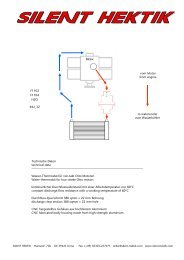
ASSEMBLY AND ADJUSTMENT OF THE PICKUPS WITH MOTOPLAT- REPLACEMENT:As CDI replacement the baseplate with the Pickups as well as the rotor are mounted in place ofthe ignition generator with a distance of 0.2 - 0.3mm. As a rough adjustment the left over edgeof the rotor should be approximately at the middle of the Pickup centre, in a clockwise direction.The mechanical basic adjustment refers to the static ignition timing of 6° BTDC.By turning the baseplate with the Pickups the static ignition timing of both cylinders by means ofa stroboskop-light will be adjusted to approx. 1200 RPM.ASSEMBLY AND ADJUSTMENT OF THE PICKUPS WITH BOSCH REPLACEMENT:The Pickkup`s distance is adjusted to 0.2 - 0.3mm with the Ducati tool or a SH tool. Instead ofthe tools you can also use the dismanted ignition rotor on a central wave to adjust the distance:see photo on the right.The static ignition timing is in the turning direction of the left over edge of the ignition rotor. ForSinglespark this edge should be in the middle of the Pickup`s centre with 8° BTDC <strong>and</strong> <strong>for</strong>Twinspark (double ignition) with 6° BTDC.For the basic adjustment of the Pickups you can use the Ducati tool or the SH tool. With the SHtool you draw near the 5mm bulge of the tool. With the Ducati tool the round Pickup centreshould lie in the middle of the bulge.After successful <strong>assembly</strong> <strong>and</strong> adjustment the static ignition timing of both cylinders approx.1200 RPM with 8° or 6° BTDC, should be checked with a stroboskop-light.With the SH ignition box, because of tolerance <strong>and</strong> magnetic interaction, two ignition spark cancome through the level of the triggernose. In this case, the level of the triggernose should beturned with a machine or straightened with a file. When filing, it is enough if the front nose areais sloped. The back nose area should stay the original 5mm lenght. The nose lenght must stayunchanged. For maximum precision with Twinspark ignitions the triggernose should be turned.On the TEC ignition-coils the plus is black.CONNENCTION DIAGRAMM FOR BOSCH - BOXES :front cylinder back cylinder MotoCoilhorizontalvertikalBosch-Pickup: white (+) w-black (-) white (+) w-black (-)SH-Pickup : red (+) black (-) red (+) black (-)Output : blue-black red-black -> Minus - (Kl 1)Plus : red red -> Plus + (Kl 15)Minus : braun braunCONNENCTION DIAGRAMM FOR BOSCH & MOTOPLAT REPLACEMANT :+12V ZündschlossLinksLinksRechtsBatt.-Minus an GetriebeRechts<strong>Silent</strong> <strong>Hektik</strong>DensoCoil 4OhmMonoBlock12V 2x 7ADensoCoil 4OhmLeft output = vertikal = green Right output = horizontal = black one plus 12V input is enoughSILENT HEKTIK Hansastr. 72b 59425 Unna Germany T. (+49) 02303-257070 F. (+49) 02303-257071 www.SILENT-HEKTIK.com Page 4 of 6
The 16 timing-curves of the PowerBlock - ignition from Version KD_14CK switch positions:34° BTDC curves————————Nr. F XLNr. E LNr. D MNr. C S9ooo RPM max.MotoCoil D-Well32° BTDC curves————————Nr. B XLNr. A LNr. 9 MNr. 8 S12ooo RPM max.MotoCoil D-Well28° BTDC curves————————Nr. 7 XLNr. 6 LNr. 5 MNr. 4 S12ooo RPM max.TwinCoil D-Well26° BTDC curves————————Nr. 3 XLNr. 2 LNr. 1 MNr. 0 S12ooo RPM max.TwinCoil D-WellSILENT HEKTIK Hansastr. 72b 59425 Unna Germany T. (+49) 02303-257070 F. (+49) 02303-257071 www.SILENT-HEKTIK.com Page 5 of 6
ADRESSE ::::TEL-NUMBER :FAX-NUMBER :HOMEPAGE :SHIPPING :SILENT HEKTIKHANSASTR. 72BD-59425 UNNAGERMANY+49-2303-257070+49-2303-257071WWW.SILENT-HEKTIK.COMWORLDWIDEMember of:SILENT HEKTIK Hansastr. 72b 59425 Unna Germany T. (+49) 02303-257070 F. (+49) 02303-257071 www.SILENT-HEKTIK.com Page 6 of 6