assembly instructions for the icm assembly ... - Silent Hektik
assembly instructions for the icm assembly ... - Silent Hektik
assembly instructions for the icm assembly ... - Silent Hektik

Create successful ePaper yourself
Turn your PDF publications into a flip-book with our unique Google optimized e-Paper software.
ASSEMBLY INSTRUCTIONS FOR THE ICM<br />
ASSEMBLY INSTRUCTIONS FOR THE ICM<br />
ICM_E_04f (c)1997-2008 8. Juli 2009<br />
SILENT HEKTIK Hansastr. 72b 59425 Unna Germany Tel. (+49) 02303-257070 Fax. (+49) 02303-257071 Page 1
ASSEMBLY INSTRUCTIONS FOR THE ICM<br />
SAFETY REQUIREMENTS AND COMMENTS:<br />
Attention: HIGH VOLTAGE! DANGER ! Attention, flammable fuel: DANGER OF FIRE AND POISONING !<br />
To prevent any damage to persons or goods when working on vehicles with fully electronical, digital high-voltage ignitions and<br />
fuel injections please take notice of <strong>the</strong> following:<br />
� read <strong>the</strong> manual carefully and completely and follow all <strong>instructions</strong><br />
� Installation and operating of <strong>the</strong> ICM requires specialized knowledge and special tooling<br />
� People having a cardiac pacemaker shouldn’t work on electronic ignitions<br />
� To synchronize <strong>the</strong> carburetors NEVER pull off a sparkplug-socket but use a gauge<br />
� Never touch or pull off an ignition wire with <strong>the</strong> engine running or while starting<br />
� Connect or disconnect any ICM wiring only with <strong>the</strong> ignition switched off<br />
� Connect high voltage cable with or without sparkplug-socket to ground after removing<br />
� The per<strong>for</strong>mance control of <strong>the</strong> high-voltage block by using a spark line against ground causes damage<br />
� Always switch off <strong>the</strong> ignition when washing <strong>the</strong> bike or <strong>the</strong> engine<br />
� When electric-welding disconnect <strong>the</strong> ignition module off <strong>the</strong> wiring harness<br />
� Starting aid by using an express-charger shouldn’t be operated more than 1 minute with a maximum of 15V<br />
� No warranty respectively <strong>the</strong> correctness of <strong>the</strong> ICM-data on modified eng., a tuning by <strong>the</strong> tuner is absolutely necessary<br />
� Pay attention to unleaky fuel pressure hoses; -protect eyes, face & hands against fuel<br />
� Catch escaping fuel immediately with a adequate container -work in well ventilated rooms only<br />
� Smoking, eating and drinking is absolutely <strong>for</strong>bidden -open spark-lines are not allowed<br />
� Guarantee -, Replacement or claim <strong>for</strong> compensation only in reference to <strong>the</strong> supplied electronic<br />
� Mistakes and changes in future to be accepted.<br />
SPECIFICATION AND PARTS-LIST :<br />
1 piece ICM central unit<br />
1 piece ICM monitor software on a 3,5” disk<br />
1 piece Sub-D9 PC-cable, serial<br />
1/2 piece Power ignition coils<br />
2/4 piece Power ignition wire NEW<br />
2 piece Throttle body’s , assembled<br />
1 piece pump block, assembled<br />
2 m pressure hose 2mm Polyamide<br />
1 m fuel hose 6x2mm, w/o fabric<br />
1 piece metal fuel-filter plus two 90° fittings<br />
2 piece temperature sensor with nut, stainless steel<br />
1 piece plug- and socket-grease<br />
10 piece cable-tie small<br />
10 piece cable-tie big<br />
1 piece pickup with rotor and socket (Guzzi & BMW)<br />
1 piece pickup counter-socket (Guzzi & BMW)<br />
ASSUMPTION FOR THE ASSEMBLY:<br />
1 piece Timer socket, 25 poles<br />
1 piece Timer socket, 3 poles with rubber spout<br />
4 piece Timer socket, 2 poles with rubber spout<br />
38 piece Timer power contacts 1-1,5 qmm<br />
5 piece FastOn plug, 6,3mm with spout<br />
3 piece Crimp eyes, 5mm lug<br />
1,3 m 1,5 mm² cable, red<br />
1,3 m 1,5 mm² cable, blue<br />
7 m 1,0 mm² cable, red<br />
2,5 m 1,0 mm² cable, blue<br />
1,3 m 1,0 mm² cable, black<br />
1,3 m 1,0 mm² cable, green<br />
1,3 m 1,0 mm² cable, grey<br />
1,3 m 1,0 mm² cable, brown<br />
1,3 m 1,0 mm² cable, yellow-green<br />
1,3 m 1,0 mm² cable, yellow<br />
1,3 m 1,0 mm² cable,white<br />
5,5 m 4 mm Insulation-tube, black<br />
1,5 m 5 mm Insulation-tube, black<br />
Specialized knowledge regarding motorbike-technique and vehicle-electronic; in particular in motormanagement & -tuning. Complete<br />
workshop equipment with tooling, test- and diagnosis-devices.<br />
IBM compatible PC with WIN 98, NT, WIN2000 or XP operatind system <strong>for</strong> diagnosis and mapping.<br />
Crimp-pliers with grip-pliers-mechanism <strong>for</strong> <strong>the</strong> AMP-Timer-Power-contacts 1-1,5 mm² (can be purchased from us), de-insulationpliers,<br />
test-lamp, strobe-light.<br />
WARNING:<br />
This engine management with all parts does not comply with federal safty regulations <strong>for</strong> standard aircraft. This engine management<br />
with all parts is <strong>for</strong> use in experimental and ultralight uncertified aircrafts only and only in circumstances in which an engine<br />
managment failure will not compromise safty. The user Be<strong>for</strong>e operating this engine management with all parts read operators<br />
manual. The use of SH products in experimental and ultralight aircrafts lies expressly in <strong>the</strong> responsibility of <strong>the</strong> user. The user has<br />
to guarantee and answer <strong>for</strong> <strong>the</strong> function after installation of all <strong>Silent</strong> <strong>Hektik</strong> parts by thorough test. Engines in ultralight uncertified<br />
aircrafts can stop during flight.<br />
SILENT HEKTIK Hansastr. 72b 59425 Unna Germany Tel. (+49) 02303-257070 Fax. (+49) 02303-257071 Page 2
SENSORS:<br />
ASSEMBLY INSTRUCTIONS FOR THE ICM<br />
The ICM-box is able to work with up to 10 analog inputs. 1.Air-pressure sensor, 2.voltage, 3.CO-potentiometer, 4.throttlepotentiometer,<br />
5.left-hand PM-sensor, 6.right-hand RPM sensor, 7.air-temperature, 8.engine-temperature, 9.left-hand Lambdaprobe,<br />
10. Right-hand Lambda-probe.<br />
The airpressure-sensor, <strong>the</strong> CO-potentiometer as well as <strong>the</strong> voltage-reading is located inside <strong>the</strong> ICM-box; no <strong>assembly</strong> necessary.<br />
The throttle-potentiometer is already installed on <strong>the</strong> right-hand throttle body, so no <strong>assembly</strong> required ei<strong>the</strong>r. Both Lambda<br />
probes are not included in <strong>the</strong> specifications; an optional <strong>assembly</strong> is possible.<br />
To mount on <strong>the</strong> vehicle <strong>the</strong>re are only both temperature sensors left as well as in case of Guzzi & BMW <strong>the</strong> pickup.<br />
AIR-TEMPERATURE-SENSOR:<br />
The air- and engine-temperature-sensors are identical. The stainless steel case has a M10x1mm<br />
thread like <strong>the</strong> small spark plugs.<br />
The air-temperature sensor can be mounted on top or at <strong>the</strong> back of <strong>the</strong> airbox. To prevent <strong>the</strong><br />
airbox from cracking by vibrations <strong>the</strong> use of a small aluminum-plate with a thread on <strong>the</strong> inner<br />
side of <strong>the</strong> box is recommended.<br />
When using open intakes <strong>the</strong> sensor should be mounted near <strong>the</strong> intakes. Mount <strong>the</strong> sensor to <strong>the</strong><br />
frame with <strong>the</strong> biggest distance to engine possible.<br />
Ducati 900SS ´93<br />
ENGINE-TEMPERATURE-SENSOR:<br />
The air- and engine-temperature-sensors are identical. The stainless steel case has a M10-1mm<br />
thread like <strong>the</strong> small spark plugs.<br />
Mounting on a Guzzi: Thread in <strong>the</strong> cooling fins of <strong>the</strong> Z-head above or next to <strong>the</strong> inletmanifold,<br />
or hole in <strong>the</strong> valve-cover<br />
Mounting on a BMW: Thread in <strong>the</strong> cooling fins of <strong>the</strong> Z-head above or next to <strong>the</strong> inletmanifold<br />
Mounting on a Ducati: in <strong>the</strong> front upper valve-cover of <strong>the</strong> horizontal cylinder<br />
We do not recommend an installation on or in <strong>the</strong> oil-pan as it could cause leakage’s due to <strong>the</strong><br />
low torque when tightening <strong>the</strong> sensor.<br />
The plus-pole of <strong>the</strong> temperature sensor is <strong>the</strong> same as on <strong>the</strong> injection-jets: see plus-symbol<br />
Ducati 900M/SS in <strong>the</strong> fins<br />
useable solution, optical OK<br />
2V-Boxer R100R<br />
2V-Boxer R100R<br />
Thread in <strong>the</strong> fins, simple and OK<br />
Guzzi 1100 Sport Thread in <strong>the</strong> fins<br />
simple solution but OK<br />
SILENT HEKTIK Hansastr. 72b 59425 Unna Germany Tel. (+49) 02303-257070 Fax. (+49) 02303-257071 Page 3<br />
Guzzi - 1100Sport
ASSEMBLY INSTRUCTIONS FOR THE ICM<br />
MAGNETIC POLARIZATION OF THE BOSCH ALTERNATOR - GUZZI AND BMW:<br />
For a faultless function of <strong>the</strong> ignition system <strong>the</strong> south-pole has to be on <strong>the</strong> slip<br />
rings of <strong>the</strong> Bosch-alternator-rotor. Up tonow that’s been standard on all OEM<br />
alternator-rotors. Aftermarket or exchange alternator-rotors are very often poled <strong>the</strong><br />
opposite way. With a compass <strong>the</strong> polarization can be checked easily. With <strong>the</strong> ignition<br />
switched off <strong>the</strong> north-pole of <strong>the</strong> compass is drawed to <strong>the</strong> rotor by his south-pole.<br />
The correct polarization of <strong>the</strong> alternator-rotor can be achieved by changing <strong>the</strong> rotor<br />
or exchanging <strong>the</strong> of <strong>the</strong> alternator carbon brushes. We recommend to use a correct<br />
alternator-rotor as <strong>the</strong> per<strong>for</strong>mance of <strong>the</strong> alternator will increase by that. By<br />
exchanging <strong>the</strong> carbon-brushes <strong>the</strong> left-hand brush needs to be insulated like <strong>the</strong><br />
right-hand one. Original insulation material can be purchased from every specialized<br />
dealer. The magnetic polarization of Saprisa-alternators or Ducati-alternators doesn’t<br />
need checking.<br />
PICK UP AND ALTERNATOR-ROTOR GUZZI & BMW :<br />
The ignition rotor needs to be mounted on <strong>the</strong> alternator-rotor. There<strong>for</strong>e use <strong>the</strong><br />
original screws. Please check <strong>the</strong> connecting surface of <strong>the</strong> rotor and remove<br />
eventually excisting grades which can be found through <strong>the</strong> wearing of <strong>the</strong> lock-plate<br />
very often.<br />
The Pickup has to be mounted to <strong>the</strong> Bosch alternator with <strong>the</strong> screws of <strong>the</strong> U-V-Wsocket.<br />
At <strong>the</strong> Saprisa-alternator you are using <strong>the</strong> original screw with <strong>the</strong> 5mm spacer;<br />
moreover a 5mm thread has to be attached to <strong>the</strong> alternator.<br />
The distance between rotor and pickup should be 0.2-0.3 mm on all wings. The basic<br />
mechanical adjustment relates to <strong>the</strong> static ignition-moment:<br />
Guzzi Cali`s & Tourer 4°-6° BTDC Guzzi all LM`s 8° BTDC<br />
Ducati, all models 6° BTDC BMW all 2V-boxer 6° BTDC<br />
For <strong>the</strong> basic adjustment use <strong>the</strong> right-hand cylinder and <strong>the</strong> corresponding ignitionrotor-wing<br />
like shown on <strong>the</strong> picture.<br />
The leaving edge of <strong>the</strong> rotor should be located at <strong>the</strong> center of <strong>the</strong> pickup steel-core;<br />
The wing is rotating clockwise. To hold <strong>the</strong> rotor when tightening use <strong>the</strong> wrench of a<br />
cutting-off grinder.<br />
Check <strong>the</strong> static ignition timing with a strobe-tool at 1200 rpm & 0%TPS & 90°C. Below<br />
980 rpm & > 0%TPS & < 70°C <strong>the</strong> idle-stabilization is working.<br />
The left cylinder doesn’t require any adjustment.<br />
IGNITION COILS:<br />
Exchange <strong>the</strong> original coils by <strong>the</strong> <strong>Silent</strong> <strong>Hektik</strong> coils. In principle powercoils should<br />
always be cooled by <strong>the</strong> riding-air if possible -> mount below <strong>the</strong> steering head.<br />
Under <strong>the</strong> assumption that <strong>the</strong> ignition system is working properly <strong>the</strong> electrode-gap<br />
can amount to 0,5-0,7mm.<br />
Please use only interference-free coil- and sparkplug-sockets with a minimum<br />
resistance of 5 kW as well as resistor sparkplugs. This fully electronic system will only<br />
work properly with a very good interference suppression.<br />
Only coils with a primary resistance of at least 3 OHM are allowed. -> loss of<br />
guarantee!!! When switching off <strong>the</strong> engine <strong>the</strong> power-box of <strong>the</strong> module will be<br />
switched off after a few seconds. Please remind this fact when working on it!<br />
Electronic rev-counters are to be connected to clamp K_1 of <strong>the</strong> coil.<br />
The rev-counter outlet of <strong>the</strong> box is supplying half of <strong>the</strong> Rpm`s <strong>for</strong> some Guzzi<br />
models.<br />
ADJUSTMENT:<br />
As a basic adjustment <strong>for</strong> ALL singlespark-ignitions (standard ignitions) <strong>the</strong> 34° curves<br />
are coming into question.<br />
Guzzi Cali`s & Tourer Nr. A Guzzi all LM`s Nr. E<br />
Ducati, all models Nr. D BMW all 2V-boxer Nr. C<br />
At engine “ping”, like when using low quality fuel or by running a sidecar please use<br />
<strong>the</strong> next flater level curve with 34° BTDC. To adjust a Twinspark ignition (two<br />
sparkplugs) it needs a lot of experience and sure instinct. We recommend to follow<br />
<strong>the</strong> <strong>instructions</strong> of <strong>the</strong> tuner. When adjusting yourself please start with <strong>the</strong> following<br />
adjustments and try <strong>the</strong> curves below or above while riding <strong>the</strong> bike:<br />
Up to ˘ 90mm and up to a compression ratio of 10:1 Nr.6<br />
Up to ˘ 90mm and from a compression ratio of 10:1 upwards Nr.5<br />
At maximum driving-dynamic and smoo<strong>the</strong>st engine-running <strong>the</strong> adjustment is<br />
finished. With compression over 1:10 you should use radio compressed spark plugs.<br />
Compass-north to Bosch alternator-south<br />
Pickup on Bosch-altn.- right hand cylinder<br />
Pickup on Saprisa-altern. - right cylinder<br />
Coil-installation on a boxer, new frame<br />
Coil-installation on Guzzi 1100 Sport<br />
SILENT HEKTIK Hansastr. 72b 59425 Unna Germany Tel. (+49) 02303-257070 Fax. (+49) 02303-257071 Page 4
ASSEMBLY INSTRUCTIONS FOR THE ICM<br />
INSTALLATION OF THE PICKUPS AND THE ROTOR :<br />
The ignition rotor needs to be mounted to <strong>the</strong> crankshaft. There<strong>for</strong>e use <strong>the</strong><br />
original screws. Please check <strong>the</strong> connecting surface of <strong>the</strong> rotor and remove<br />
eventually excisting grades which can be found through <strong>the</strong> wearing of <strong>the</strong> lockplates<br />
very often.<br />
On Ducati belt-engines ei<strong>the</strong>r <strong>the</strong> original Kokusan pickup can be used<br />
Sensor-plus = yellow sensor-minus=black<br />
Or <strong>the</strong> supplied <strong>Silent</strong> <strong>Hektik</strong> pickup:<br />
Sensor-plus =red sensor-minus=black<br />
The distance between rotor and pickup should be 0,3-0,6 mm on all wings. The<br />
basic mechanical adjustment relates to <strong>the</strong> static ignition-moment of 6°-8° BTDC<br />
<strong>for</strong> all models = rear picture <strong>for</strong> <strong>the</strong> rear/vertical cylinder.<br />
For <strong>the</strong> basic adjustment use <strong>the</strong> right hand (rear/vertical) cylinder and <strong>the</strong><br />
corresponding ignition-rotor-wing like shown on <strong>the</strong> picture.<br />
The leaving edge of <strong>the</strong> rotor should be located at <strong>the</strong> center of <strong>the</strong> pickup steelcore.<br />
Please pay attention to <strong>the</strong> direction of <strong>the</strong> rotation.<br />
Ducati beltdrive right = rear/vertical left = front/horizontal<br />
Ducati bevel right = rear/vertical left = front/horizontal<br />
Guzzi right = right-hand left = left-hand<br />
Check <strong>the</strong> static ignition timing with a strobe-tool at 1200 rpm & 0%TPS & 90°C.<br />
Below 980 rpm & > 0%TPS & < 70°C <strong>the</strong> idle-stabilization is working.<br />
The left (front/horizontal) cylinder doesn’t require any adjustment.<br />
INSTALLATION OF THE COILS:<br />
The coils are replacing <strong>the</strong> original coils. Depending on <strong>the</strong> model <strong>the</strong> mounting<br />
supports will fit. When laying <strong>the</strong> wiring please make sure you to use <strong>the</strong> biggest<br />
distance between <strong>the</strong> pickup wiring and <strong>the</strong> ignitions-cables to prevent any<br />
interference’s. The coils should be could by <strong>the</strong> riding wind.<br />
The crankcase has to have a very good ground-connection to <strong>the</strong> battery -><br />
Battery ground wire to crankcase!<br />
Under <strong>the</strong> assumption that <strong>the</strong> ignition system is working properly <strong>the</strong> electrodegap<br />
can amount to 0,5-07mm.<br />
Please use only interference-free coil- and sparkplug-sockets with a minimum<br />
resistance of 5 kW as well as resistor sparkplugs. This fully electronic system will<br />
only work properly with a very good interference suppression; especially in<br />
combination with old alternator regulators. Please protect all socket-connections<br />
with socket-grease against humidity. Never use any battery-pole-grease as this kind<br />
of grease is alcalic. Soldered crimp-connections do brake and cause malfunctions<br />
through engine vibration. Defective Engine-stop switches mounted on handlebars<br />
and side-stands are very often a source of problems.<br />
Only coils with a primary resistance of at least 3 OHM are allowed. -> loss of<br />
guarantee!!! When switching off <strong>the</strong> engine <strong>the</strong> power-box of <strong>the</strong> module will be<br />
switched off after a few seconds. Please remind this fact when working on it!<br />
Older rev-counters can be connected to <strong>the</strong> grey output of <strong>the</strong> box. Newer revcounters<br />
can be connected to <strong>the</strong> coil socket KL1-. The box won’t be destroyed by<br />
trying out.<br />
ADJUSTMENT:<br />
As a basic adjustment <strong>for</strong> ALL singlespark-ignitions (standard ignitions) <strong>the</strong> 34°<br />
curves are coming into question.<br />
All Tourer, Comp. Ratio 1:9 Nr. E<br />
At engine “ping”, like when using low quality fuel or by running a sidecar please<br />
use <strong>the</strong> next flater level curve with 34° BTDC. To adjust a Twinspark ignition (two<br />
sparkplugs) it needs a lot of experience and sure instinct. We recommend to<br />
follow <strong>the</strong> <strong>instructions</strong> of <strong>the</strong> tuner. When adjusting yourself please start with <strong>the</strong><br />
following adjustments and try <strong>the</strong> curves below or above while riding <strong>the</strong> bike:<br />
Up to ˘ 90mm and up to a compression ratio of 10:1 Nr. 6<br />
Up to ˘ 90mm and from a compression ratio of 10:1 upwards Nr. 5<br />
from ˘ 92mm and up to a compression ratio of 10:1 Nr. 2<br />
from ˘ 92mm and from a compression ratio of 10:1 upwards Nr. 2<br />
At maximum driving-dynamic and smoo<strong>the</strong>st engine-running <strong>the</strong> adjustment is<br />
finished. From compressions ratios of 10:1 upwards interference-free sparkplugs<br />
have to be used.<br />
static ignition timing at <strong>the</strong> pickup<br />
<strong>for</strong> <strong>the</strong> back cylinder (right) at ca. 6°-8° BTDC<br />
static timing 6°-8° BTDC<br />
all modells - singel- & twin-spark<br />
Check <strong>the</strong> static timing at 1200 RPM <strong>for</strong> <strong>the</strong> back<br />
cylinder with a timing light through <strong>the</strong> window<br />
( <strong>for</strong> racing-cams MIDDLE screw-head )<br />
Coil-installation on frame <strong>for</strong> air-cooling<br />
SILENT HEKTIK Hansastr. 72b 59425 Unna Germany Tel. (+49) 02303-257070 Fax. (+49) 02303-257071 Page 5
80<br />
5<br />
35<br />
ASSEMBLY INSTRUCTIONS FOR THE ICM<br />
R35<br />
105<br />
THE INTAKE CHANNEL:<br />
The intakes of both cylinders have to<br />
be enlarged around 4mm out of <strong>the</strong><br />
center and tapered adapted to <strong>the</strong><br />
mounting distance on a length of<br />
about 40 – 50mm. By this chance <strong>the</strong><br />
ports around <strong>the</strong> valve guides can be<br />
widened on both sides around 1-<br />
2mm.<br />
For <strong>the</strong> installation of <strong>the</strong> intake parts<br />
<strong>the</strong> paper gaskets should be fitted<br />
with a bit of Hylomar.<br />
The 944cc cylinders have to be installed<br />
as per <strong>the</strong> Ducati workshop<br />
manual.<br />
At <strong>the</strong> 900M <strong>the</strong> engine can remain in<br />
<strong>the</strong> frame; at <strong>the</strong> 900SS <strong>the</strong> engine has<br />
to be removed.<br />
It is a lot easier if <strong>the</strong> piston is installed<br />
in <strong>the</strong> cylinder on a bench first<br />
be<strong>for</strong>e connecting it to <strong>the</strong> conrod.<br />
Nei<strong>the</strong>r cylinder nor pistons should be<br />
rubbed with oil or grease; <strong>the</strong> factory<br />
coating is perfect <strong>for</strong> <strong>the</strong> first run in.<br />
Inside <strong>the</strong> combustion chamber <strong>the</strong><br />
edges of <strong>the</strong> squeeze-edge should be<br />
modified to a 2mm radius.<br />
THE INTAKE FUNNELS:<br />
Both funnels had been computerdesigned<br />
especially <strong>for</strong> <strong>the</strong> Ducati<br />
engine. Even though <strong>the</strong>y are quite<br />
long a maximum RPM of 11.000 RPM is<br />
possible.<br />
At <strong>the</strong> 900SS both funnels lead into<br />
<strong>the</strong> original airbox-holes. No fur<strong>the</strong>r<br />
modifications are required.<br />
At <strong>the</strong> 900M <strong>the</strong> left body has to be<br />
mounted below a crosswise strut and<br />
<strong>the</strong>re<strong>for</strong>e a new hole <strong>for</strong> <strong>the</strong> funnel is<br />
required.<br />
This hole can be cut into <strong>the</strong> plastic of<br />
<strong>the</strong> airbox by using a sharp knife or a<br />
fine saw blade.<br />
Due to <strong>the</strong> curve of <strong>the</strong> funnel an oval<br />
hole is required; <strong>the</strong> funnel might<br />
touch <strong>the</strong> inner side of <strong>the</strong> airbox and<br />
<strong>the</strong>re<strong>for</strong>e might need to be adapted a<br />
few millimeters (see right-hand picture)<br />
SILENT HEKTIK Hansastr. 72b 59425 Unna Germany Tel. (+49) 02303-257070 Fax. (+49) 02303-257071 Page 6
ASSEMBLY INSTRUCTIONS FOR THE ICM<br />
BEVEL-DRIVE:<br />
At bevel drive engines <strong>the</strong> original<br />
intake funnels can be used. Pay attention<br />
to <strong>the</strong> flame-sieves to avoid unpleasant<br />
hot calfs.<br />
THE PUMP-BLOCK:<br />
At <strong>the</strong> 944ie kit <strong>the</strong> pump-block has to<br />
be mounted to <strong>the</strong> back of <strong>the</strong> airbox<br />
with 4 screws, in direction to <strong>the</strong> Battery.<br />
900 M/SS BELT DRIVE:<br />
The 944ie kit is perfectly designed <strong>for</strong><br />
<strong>the</strong> use on a 900SS. The intake funnels<br />
fit right into <strong>the</strong> airbox. -> see right<br />
At <strong>the</strong> Monster-models you have to<br />
create a hole as a crosswise strut of<br />
<strong>the</strong> frame is in <strong>the</strong> way of <strong>the</strong> rear/<br />
standing cylinder. For use in competition<br />
this strut should be moved to<br />
achieve an optimum <strong>for</strong> <strong>the</strong> intakesystem.<br />
STOCK - MANIFOLDS<br />
For <strong>the</strong> 900 SS & Monster belt-drive<br />
models we also sell 42mm bodys <strong>for</strong><br />
<strong>the</strong> stock-manifolds.<br />
The original rubber-parts are used<br />
with it.<br />
The pump-block finds a place on <strong>the</strong><br />
frond side of <strong>the</strong> air-box.<br />
SILENT HEKTIK Hansastr. 72b 59425 Unna Germany Tel. (+49) 02303-257070 Fax. (+49) 02303-257071 Page 7<br />
PS<br />
100<br />
90<br />
80<br />
70<br />
60<br />
50<br />
40<br />
4ooo<br />
6ooo<br />
8ooo<br />
DIN-PERFORMANCE:<br />
900M Serie<br />
944ie<br />
944SS Mikuni<br />
10ooo<br />
red = ICM mit 944ccm 95 HP<br />
gray = Mikuni mit 944ccm 84 HP<br />
blue = Serie mit 904ccm 73 HP<br />
U/min<br />
Nm<br />
100<br />
80<br />
60<br />
40
ASSEMBLY INSTRUCTIONS FOR THE ICM<br />
THE THROTTLE BODIES AND THE JETS:<br />
The throttle bodies are replacing <strong>the</strong> carburetors and are to be mounted to <strong>the</strong> standard intakes. For <strong>the</strong> pivot of <strong>the</strong> throttle<br />
bodies on BMW <strong>the</strong> standard throttle cables as well as <strong>the</strong> original throttle-handle <strong>for</strong> <strong>the</strong> 40´ Bing carbs can be used. For Ducati<br />
and Guzzi you`ll need to install a Tommaselli throttle-handle in combination with LM1 throttle cables. The cables should have a<br />
back lash of about 1mm.<br />
The adjustment of <strong>the</strong> idle as well as <strong>the</strong> synchronization of <strong>the</strong> throttle valves have to be done via <strong>the</strong> block-screws on <strong>the</strong> inside.<br />
The procedure is quite <strong>the</strong> same as in case of carburetors. Engine-revs via throttle block-screws, air-fuel-mixture via map-figures of<br />
<strong>the</strong> ICM-monitor. The adjustment with <strong>the</strong> maximum rev`s of <strong>the</strong> engine when idling is <strong>the</strong> correct adjustment. The idle should be<br />
between 1050 and 1100 RPM with <strong>the</strong> engine at normal operating temperature. When <strong>the</strong> adjustment is finished, <strong>the</strong> ICM-box<br />
should be switched off and on once to save all parameters.<br />
BMW 2Ventil-Boxer 40er Bing replacement Ducati beltdrive 38er Mikuni replacement Guzzi Big-Block 40er DellOrto replacement<br />
On <strong>the</strong> right-hand throttle body you`ll find <strong>the</strong> throttle-potentiometer. This sensor is recording <strong>the</strong> angle of <strong>the</strong> throttle valves<br />
and assigning it to <strong>the</strong> corresponding load of <strong>the</strong> engine.<br />
On <strong>the</strong> jet-brackets you`ll find two hose-connections <strong>for</strong> <strong>the</strong> fuel-lines. One line is <strong>the</strong> fuel feeding, <strong>the</strong> o<strong>the</strong>r one is <strong>the</strong> return. It<br />
doesn’t matter which one of <strong>the</strong> connections you are using what <strong>for</strong>. Please pay attention to push <strong>the</strong> stiff pressure-hoses up to<br />
<strong>the</strong> end of <strong>the</strong> connection and to tighten <strong>the</strong> cap-nuts up to <strong>the</strong> block.<br />
Via <strong>the</strong> feeding- and <strong>the</strong> return-lines <strong>the</strong> injection jets are permanently rinsed with fuel and toge<strong>the</strong>r with <strong>the</strong> very thin pressurelines<br />
a very high flow-speed is achieved, which is carrying gas-bubbles away and cooling down <strong>the</strong> injection jets.<br />
On our throttle bodies we are using 4 different types of jet-technologies. The choice depends on <strong>the</strong> specific vehicle <strong>the</strong> system is<br />
going to be used <strong>for</strong>: standard, medium and pico.<br />
For <strong>the</strong> synchronization of <strong>the</strong> throttle bodies you HAVE to use vacuum gauges. With <strong>the</strong> sparkplug-socket pulled off parts of <strong>the</strong><br />
electronics can be harmed, even if this can’t be recognized immediately.<br />
2VBoxer Cafe-Racer<br />
Guzzi 1100S<br />
Test of <strong>the</strong> injection-volume at 1,3 bar system-pressure, 12V and 20°C:<br />
Size color fuel-volume<br />
————————————————————————–———————————<br />
Standard white 17ml ^ 6,2 Ltr/h<br />
Standard beige 35ml ^ 12,6 Ltr/h<br />
Medium grey 36ml ^ 13,1 Ltr/h<br />
Medium green 32ml ^ 11,5 Ltr/h<br />
Medium black 21ml ^ 7,6 Ltr/h<br />
Pico türkis 16ml ^ 5,8 Ltr/h<br />
Pico orange 20ml ^ 7,3 Ltr/h<br />
The arrangement of <strong>the</strong> jets guarantees<br />
an optimum air-fuel-mixture as <strong>the</strong> fuel<br />
jet is heading directly into <strong>the</strong> gap of<br />
<strong>the</strong> throttle valve, where <strong>the</strong> gasflow is<br />
at <strong>the</strong> maximum speed.<br />
It has been applied <strong>for</strong> a patent <strong>for</strong> this<br />
novel procedure.<br />
SILENT HEKTIK Hansastr. 72b 59425 Unna Germany Tel. (+49) 02303-257070 Fax. (+49) 02303-257071 Page 8
ASSEMBLY INSTRUCTIONS FOR THE ICM<br />
THE PUMP-BLOCK:<br />
The feeding of <strong>the</strong> pump-block is located on <strong>the</strong> pump side,<br />
as shown on <strong>the</strong> right hand picture. The fuel needs to be<br />
filtered to avoid plugging of <strong>the</strong> jets. Use only metal-filters<br />
as <strong>the</strong> suction-volume of <strong>the</strong> pump would cause <strong>the</strong> dirt to<br />
break through paper or plastic filters. To avoid air-lock ups<br />
please mount <strong>the</strong> filter vertical right after <strong>the</strong> fuel cock.<br />
For <strong>the</strong> return-line please use <strong>the</strong> 6mm connection of <strong>the</strong><br />
pressure regulator as shown on <strong>the</strong> left side of <strong>the</strong> picture.<br />
The 4mm vacuum-connection in <strong>the</strong> center remains open<br />
Please pay attention to short and unfolded hoseconnections.<br />
Please use rubber- or silicon-hoses with an inner<br />
diameter of 6mm and a material-thickness of 1,5 to<br />
2mm.<br />
Secure all hoses on its connector against slipping off with a<br />
cable tie. The hose-system is self bleeding. Never let <strong>the</strong><br />
pumpblock run dry!<br />
The pumpblock is operating with a system pressure of 1,3<br />
bar and a current consumption of 2,5A at 12,5V. Each hour<br />
120 / 140 Liter fuel are circulating.<br />
On <strong>the</strong> pressure-side <strong>the</strong> feeding- as well as <strong>the</strong> return-line<br />
have to be mounted by using <strong>the</strong> blue cap nuts. Please pay<br />
attention to push <strong>the</strong> stiff pressure-hoses up to <strong>the</strong> end of<br />
<strong>the</strong> connection and to tighten <strong>the</strong> cap-nuts up to <strong>the</strong> block.<br />
The pumpblock can be mounted horizontal or vertical, but<br />
never direct next to heat-emitting parts like <strong>the</strong> exhaust or<br />
cylinderheads as this might cause gas-bubbles.<br />
A cooler location guarantees safe operations under hot circumstances<br />
(like stop and go traffic) and supports <strong>the</strong> lifetime<br />
of all parts.<br />
To minimize <strong>the</strong> noise of <strong>the</strong> pumpblock you can mount it<br />
on silent-blocks.<br />
With <strong>the</strong> engine switched off <strong>the</strong> pump shuts off after<br />
about 10 seconds.<br />
If possible <strong>the</strong> pumpblock should be mounted below <strong>the</strong><br />
level of <strong>the</strong> fuel tank. When mounting it above <strong>the</strong> level of<br />
<strong>the</strong> fuel tank a maximum height of 30 cm shouldn’t be exceeded.<br />
On feedings longer than 1m a check valve needs to be installed<br />
right next to <strong>the</strong> tank.<br />
The pumpblock can be used with any kind of pump gas,<br />
leaded or unleaded, mixed or with alcohol.<br />
Using additional aggressive additives can reduce <strong>the</strong> lifetime<br />
of <strong>the</strong> system dramatically.<br />
Minus on <strong>the</strong> pump; at <strong>the</strong> top of <strong>the</strong> picture – M5 nut<br />
Plus on <strong>the</strong> pump; in <strong>the</strong> button of <strong>the</strong> picture – M4 nut<br />
The 4mm tube next to <strong>the</strong> connections is not in use<br />
Pumpblock on a Ducati 900M/SS – belt drive<br />
Pumpblock on a Boxer R100R<br />
Pumpblock on a Guzzi 1100 Sport<br />
10mm out of <strong>the</strong> center<br />
SILENT HEKTIK Hansastr. 72b 59425 Unna Germany Tel. (+49) 02303-257070 Fax. (+49) 02303-257071 Page 9
THE ICM-BOX:<br />
ASSEMBLY INSTRUCTIONS FOR THE ICM<br />
The ICM-box is <strong>the</strong> heart of <strong>the</strong> system. Here all sensors and actors<br />
are connected to.<br />
On <strong>the</strong> front side you’ll find <strong>the</strong> 25 pole socket as well as <strong>the</strong> COpotentiometer<br />
(anti-clockwise is richer) left to it.<br />
On <strong>the</strong> back side you’ll find <strong>the</strong> Sub-D <strong>for</strong> <strong>the</strong> connection to <strong>the</strong> PC.<br />
As mounting location we do prefer <strong>the</strong> frame-triangle below <strong>the</strong><br />
seat. The ICM-box should be somehow protected against water.<br />
The feeding to <strong>the</strong> 25 pole socket should be handled very carefully:<br />
free of any mechanical excitement and protected against vibration<br />
and scrubbing with an Insulation-tube.<br />
First you should determine all cable length to <strong>the</strong>n lay <strong>the</strong> insulation<br />
tube. From <strong>the</strong>re it goes to <strong>the</strong> single sensors and consumers.<br />
Kabelbinder<br />
ICM-box in <strong>the</strong> tool-box of a Boxer<br />
14mm Iso-Rohr<br />
ICM Box on a Ducati 900M with standard airbox and<br />
small Hawker-battery. Ignition-coils are mounted to<br />
<strong>the</strong> frame.<br />
Mounting <strong>the</strong> ICM under <strong>the</strong> seat is more useful.<br />
The wiring harness should be laid from <strong>the</strong> ICM-box to <strong>the</strong> single components.<br />
Care and a very good crimp-pliers are <strong>the</strong> basic assumptions.<br />
5mm Iso-Rohr<br />
ICM-box under <strong>the</strong> seat of a Guzzi 1100 Sport<br />
SILENT HEKTIK Hansastr. 72b 59425 Unna Germany Tel. (+49) 02303-257070 Fax. (+49) 02303-257071 Page 10
Schalter<br />
ASSEMBLY INSTRUCTIONS FOR THE ICM<br />
4D - Kennfeld Umschaltung für ICM 11-2006<br />
Index F E D C B A 9 8 7 6 5 4 3 2 1 0<br />
Last 0 2 4 7 11 16 22 28 34 40 47 54 60 67 73 80%<br />
Offset 8 8 8 8 8 8 8 8 7 6 5 4 3 2 1 0°<br />
————————————————————————————————————————————————————————————————<br />
150°C 20 20 20 20 20 20 20 20 19 18 17 16 15 14 13 12°<br />
140°C 22 22 22 22 22 22 22 22 21 20 19 18 17 16 15 14°<br />
0 22 22 22 22 22 22 22 22 21 20 19 18 17 16 15 14°vOT<br />
23 23 23 23 23 23 23 23 23 21 20 19 18 17 16 15°<br />
1 24 24 24 24 24 24 24 24 23 22 21 20 19 18 17 16°<br />
25 25 25 25 25 25 25 25 24 23 22 21 20 19 18 17°<br />
2 26 26 26 26 26 26 26 26 25 24 23 22 21 20 19 18°<br />
27 27 27 27 27 27 27 27 26 25 24 23 22 21 20 19°<br />
3 28 28 28 28 28 28 28 28 27 26 25 24 23 22 21 20°<br />
4 29 29 29 29 29 29 29 29 28 27 26 25 24 23 22 21°<br />
5 30 30 30 30 30 30 30 30 29 28 27 26 25 24 23 22°<br />
6 31 31 31 31 31 31 31 31 30 29 28 27 26 25 24 23°<br />
7 32 32 32 32 32 32 32 32 31 30 29 28 27 26 25 24°<br />
33 33 33 33 33 33 33 33 32 31 30 29 28 27 26 25°<br />
8 34 34 34 34 34 34 34 34 33 32 31 30 29 28 27 26°<br />
35 35 35 35 35 35 35 35 34 33 32 31 30 29 28 27°<br />
9 36 36 36 36 36 36 36 36 35 34 33 32 31 30 29 28°<br />
37 37 37 37 37 37 37 37 36 35 34 33 32 31 30 29°<br />
A 38 38 38 38 38 38 38 38 37 36 35 34 33 32 31 30°<br />
39 39 39 39 39 39 39 39 38 37 36 35 34 33 32 31°<br />
B 40 40 40 40 40 40 40 40 39 38 37 36 35 34 33 32°<br />
41 41 41 41 41 41 41 41 40 39 38 37 36 35 34 33°<br />
C 42 42 42 42 42 42 42 42 41 40 39 38 37 36 35 34°<br />
43 43 43 43 43 43 43 43 42 41 40 39 38 37 36 35°<br />
D 44 44 44 44 44 44 44 44 43 42 41 40 39 38 37 36°<br />
45 45 45 45 45 45 45 45 44 43 42 41 40 39 38 37°<br />
E 46 46 46 46 46 46 46 46 45 44 43 42 41 40 39 38°<br />
47 47 47 47 47 47 47 47 46 45 44 43 42 41 40 39°<br />
F 48 48 48 48 48 48 48 48 47 46 45 44 43 42 41 40°vOT<br />
————————————————————————————————————————————————————————————————<br />
Grafik zeigt die Zündkurven Schalter A, 9, 8, 7 ab 80% Last<br />
°vOT<br />
5°<br />
30°<br />
28°<br />
26°<br />
24°<br />
Stat. ZZP = 5°vOT für alle Kurven + Felder als Bezugsgröße für Daten<br />
Die Auswahl des Zündkennfeldes bezieht sich auf den max. Zündwinkel<br />
ab 80% Drosselklappe. Abweichende stat. Zündwinkel werden dazu addiert<br />
bzw. subtrahiert:<br />
zB. Guzzi LM2 = 33° bei 8°stat. = A (30° bei 5°stat.)<br />
zB. Guzzi Cal2 = 33° bei 2°stat. = D (36° bei 5°stat.)<br />
SILENT HEKTIK Hansastr. 72b 59425 Unna Germany Tel. (+49) 02303-257070 Fax. (+49) 02303-257071 Page 11<br />
rpm
FIRST STEPS :<br />
ASSEMBLY INSTRUCTIONS FOR THE ICM<br />
MECHANISM:<br />
After switching on <strong>the</strong> power supply <strong>the</strong> fuel pump starts running <strong>for</strong> a few seconds to bleed <strong>the</strong> system. To support <strong>the</strong> process<br />
of ventilation one pressure-return should not be connected to <strong>the</strong> body in <strong>the</strong> first stage, but somehow connected to a fuel resistant<br />
container. As soon as any air is removed out of <strong>the</strong> pumpblock <strong>the</strong> pressure hose can be connected again. The system is going<br />
to be bleeded whenever it is going to be switched on. Please pay attention to any folds of <strong>the</strong> pressure hoses.<br />
The throttle bodies should first remain open about 1,5 turns and later on fine-adjusted to about 1000 RPM.<br />
SENSORS:<br />
By switching on <strong>the</strong> power supply <strong>the</strong> ICM-box is testing all sensors and calculating <strong>the</strong> zero-level of <strong>the</strong> potentiometers. Due to<br />
this NEVER operate <strong>the</strong> throttle while switching on <strong>the</strong> unit!<br />
With <strong>the</strong> monitor-program in online-mode (F3) all components can be checked quickly. In case of malfunctioning you can use <strong>the</strong><br />
diagnosis-mode to solve <strong>the</strong> problem.<br />
START & IDLING:<br />
Start <strong>the</strong> warm engine WITHOUT operating <strong>the</strong> throttle. At engine temperature below 40°C you should open <strong>the</strong> additional airslides<br />
on <strong>the</strong> bodies (in <strong>the</strong> future <strong>the</strong>y can be operated electrical). Eventually open <strong>the</strong> throttle about 4%-8% to place a bit more<br />
air to <strong>the</strong> engines disposal at <strong>the</strong> beginning.<br />
The acceleration pump is also working without <strong>the</strong> engine running. Due to this <strong>the</strong> air-fuel mixture can be enriched be<strong>for</strong>e starting:<br />
ACSQ. ATTENTION: If used to often <strong>the</strong> engine can be “drowned”.<br />
>1,5 kRPM and > 0% throttle <strong>the</strong> dynamic acceleration-enrichment will be adjusted: ACDQ. For starting <strong>the</strong> engine <strong>the</strong> data 250<br />
are to be adjusted. To adjust <strong>the</strong> idling without a PC <strong>the</strong> CO-Poti can be used = anti-clockwise rotation make <strong>the</strong> mixer richer.<br />
For starting a cold engine <strong>the</strong> MOTOR-TEMP (MTS) figures are to be adjusted to enrich <strong>the</strong> air-fuel mixture. At extreme temperatures<br />
a cold-start-adjustment in addition to <strong>the</strong> mass-compensation can be created: LUFT-TEMP ATS (AIR-TEMP).<br />
Idling with more than 1,0 kRPM <strong>the</strong> FUEL-MAP figures have to be adjusted. The idle should first be adjusted to 5% - 6% CO or better<br />
at about 0,86La to 0,88La (Lambda) at engine on operating temperature. This figure will be registered in 750 - 1000 - 1200.<br />
Then FUEL-MAP will have to be adjusted again to 3-4% CO (0,92La – 0,95La).<br />
Above 1,5 kRPM and above 0% throttle <strong>the</strong> thrust-disconnection can be adjusted to save fuel. On 0 <strong>the</strong> thrust disconnection is<br />
switched off. If <strong>the</strong> figures are to high <strong>the</strong> fuel-film will be reduced: <strong>the</strong> engine starts stuttering and accelerates with delay.<br />
The figures below 1,5 kRPM but over 0% throttle are <strong>for</strong> starting to drive and should be a bit richer (0,84La).<br />
Should <strong>the</strong> single cylinders require different fuel-volume when idling <strong>the</strong> figures LeOF and RiOF should be adjusted. At >1,5 kRPM<br />
<strong>the</strong> dynamic offset LiOF and NLOF are necessary to calibrate <strong>the</strong> map and <strong>the</strong> injection valve to <strong>the</strong> engine horsepower.<br />
THE FUEL-MAP:<br />
The fuel volume <strong>for</strong> your engine depends on <strong>the</strong> power curve and <strong>the</strong> wanted adjustment: Figures above 1,5 kRPM (from bottom<br />
to <strong>the</strong> top) and >0% throttle (from left to right).<br />
AREA OF OPERATIONS:<br />
1) idle enriched a bit<br />
2) <strong>the</strong>oretical working area<br />
at constant acceleration<br />
and low load, independ<br />
ent from load and gear<br />
3) start-area at stop & go<br />
traffic, enriched a bit<br />
4) Full acceleration like on<br />
an acceleration-dyno or<br />
when trying to overtake;<br />
strongly enriched<br />
5) Pushing like running<br />
down a hill or in front of<br />
a traffic light, strongly<br />
leaned<br />
6) Engine RPM x 1000<br />
7) Throttle valve in percent<br />
6<br />
1<br />
THEORY:<br />
An Otto-engine needs per HP and hour about 250 grams fuel (330ml) to reach <strong>the</strong> full potential. The maximum per<strong>for</strong>mance of an<br />
Otto-engine will be reached at about 0,88La to 0,9La (slightly enriched)<br />
The lowest fuel consumption can be reached at about 1,1La. As this is extremely lean <strong>the</strong> engine starts stuttering under load and<br />
due to this it makes only sense under pushing operation.<br />
For acceleration <strong>the</strong> mixture has to be enriched to 0,78La – 0,84La to reach maximum acceleration.<br />
At Lambda 1 <strong>the</strong> engine has <strong>the</strong> lowest emission but also <strong>the</strong> lower per<strong>for</strong>mance at increased fuel consumption and higher engine<br />
temperature.<br />
At figures below 0,7La (very rich) or above 1,2La (very lean) <strong>the</strong> limit <strong>for</strong> ignition is reached, <strong>the</strong> engine starts stuttering.<br />
SILENT HEKTIK Hansastr. 72b 59425 Unna Germany Tel. (+49) 02303-257070 Fax. (+49) 02303-257071 Page 12<br />
5<br />
3<br />
2<br />
7<br />
4
TUNING:<br />
ASSEMBLY INSTRUCTIONS FOR THE ICM<br />
The tuning in practical use is <strong>the</strong> only really complicated section of <strong>the</strong> ICM-kit.<br />
During <strong>the</strong> dynamic of driving all figures of <strong>the</strong> injection-screen are meshing. It<br />
takes a lot of experience as well as time not to mix up cause and symptom.<br />
With a little time and a Lambda sensor as a measuring tool a good tuning can be<br />
reached by any dedicated user.<br />
THE BEGINNING:<br />
First 2% to 17% throttle should be adjusted on <strong>the</strong> engine (at normal operating<br />
temperature). It should be ei<strong>the</strong>r 6% to 8% or better 0,88La to 0,9La.<br />
If <strong>the</strong> figures under FUEL-MAP should go down to zero air-pressure and temperature-figures<br />
have to be decreased.<br />
With load (while starting) <strong>the</strong> figures might vary a bit, usually <strong>the</strong>y have to be<br />
enriched.<br />
Also full-throttle adjustment is possible on <strong>the</strong> highway or on a dyno. At nominal<br />
power about 0,88La to 0,9La should be adjusted.<br />
THE DRIVING AREA:<br />
The range from 10% to 60% throttle should be adjusted with a Lambda sensor<br />
while driving. This area is <strong>the</strong> one which is depending <strong>the</strong> most on <strong>the</strong> engineconcept<br />
as well as on <strong>the</strong> driving habits. Most of <strong>the</strong> motorbike riders are running<br />
<strong>the</strong>ir engines within this area.<br />
The tune up can be varied from super-dynamic (high fuel-consumption) down to<br />
a bit indolent and tired (low fuel consumption).<br />
All figures should be saved regularly while working on <strong>the</strong> adjustment, so if a<br />
tune up is wrong you can easily get back to an older but maybe better mapping.<br />
Here at <strong>Silent</strong> <strong>Hektik</strong> <strong>the</strong> following method is used:<br />
G_M0520A Guzzi – Müller – may – 20 th – A-version (1 st )<br />
D_K0317D Ducati – Kurpas – march – 17 th – D-version (4 th )<br />
B_U0403F Boxer – Uwe – april – 3 rd – F-version (6 th )<br />
With a little patience and time you’ll find your own individual adjustment at an<br />
satisfying fuel consumption.<br />
THE THRUST -DISCONNECTION:<br />
To safe fuel we are using a thrust disconnection. Under FCOQ <strong>the</strong> quantity of <strong>the</strong><br />
fuel-volume you want to reduce <strong>the</strong> total volume about can be adjusted:<br />
0/1=off 2= -3,2% 3= -6,5% 4=-12% 5=-25% 6=37% 7=-50%<br />
With FCOD <strong>the</strong> quantity (<strong>the</strong> duration) of <strong>the</strong> fuel-saving can be adjusted; depending<br />
on <strong>the</strong> bike-model and <strong>the</strong> individual driving habits an adjustment between<br />
10 and 50 is useful.<br />
Ano<strong>the</strong>r ”saving-circuit” is <strong>the</strong> constant-ride-emaciation CDFQ + CDFD. Running<br />
<strong>the</strong> engine with constant RPM and throttle-position over an extended period <strong>the</strong><br />
air-fuel-mixture is to be leaned a bit.<br />
0= off 1= -6,25% 2= -12,5% 3= -12,5% but without full throttle<br />
FOR EMISSION-CONTROL THE SAVE CIRCUITS SAM AND KFA NEEDS TO BE AD-<br />
JUSTED TO ZERO TO AVOID ANY DISTORTION OF THE READING.<br />
The full throttle adjustments can be done on<br />
<strong>the</strong> dyno or on <strong>the</strong> highway.<br />
The fuel-saving circuits have to be shut off <strong>for</strong><br />
<strong>the</strong>se measurements.<br />
SILENT HEKTIK Hansastr. 72b 59425 Unna Germany Tel. (+49) 02303-257070 Fax. (+49) 02303-257071 Page 13<br />
P = Per<strong>for</strong>mance<br />
b = fuel consumption<br />
La = Lambda<br />
Lambda-tension of <strong>the</strong> Denso probe
ASSEMBLY INSTRUCTIONS FOR THE ICM<br />
The D_ICM system on a 912<br />
It is possible to mount <strong>the</strong> ICM (single system) or <strong>the</strong> D_ICM (double system) at an engine with 80hp or 100hp. The ignition demand<br />
of both engines is identical. The demand of fuel depends on <strong>the</strong> power and also on <strong>the</strong> intake manifold and exhaust pipes of<br />
each plane. The PC-monitor software makes a fast and precise adjustment to all constellations possible.<br />
For a season independent running of <strong>the</strong> 912 power unit we recommend <strong>the</strong> application of a water <strong>the</strong>rmostat. The water temperature<br />
should be beetween 70°C and 80°C ( 90°C to 100°C head temperature) , <strong>the</strong> oel temperature beetween 90°C and 95°C<br />
to reach an optimum of efficiency and maximum lifetime.<br />
The engine should not be heavy loaded beneath 60 °C, this wears it out badly!<br />
For a safe start of <strong>the</strong> 80HP and 100HP engine we recommend <strong>the</strong> new strong electrostarter with a 12V 16Ah high quality batterie.<br />
Pay attention <strong>for</strong> <strong>the</strong> start-procedur on page 12.<br />
The Twin_ICM parts<br />
The both Bing carburators with rubbers, <strong>the</strong> complete CDI ignition with <strong>the</strong> pickups and <strong>the</strong> mechanical fuelpump will be<br />
removed from <strong>the</strong> engine. The tube between <strong>the</strong> two manyfolds and <strong>the</strong> manyfolds itselfe are in use. For syncronisation<br />
of <strong>the</strong> two inlets please use <strong>the</strong> smal vaccum connectors on <strong>the</strong> trottlebodys. The right mixture at idling is about 4%<br />
carbonmonoxid or 0,85 Lambda<br />
The air temperature sensors must have contact <strong>the</strong> incomming air but not to <strong>the</strong> warm engine or it warm parts. On<br />
composite airboxer are no problems. On aluminium airboxes an isolation is requirt. On textiles airfilters <strong>the</strong> sensor can be<br />
mounted on <strong>the</strong> rubber backside of <strong>the</strong> filters.<br />
SILENT HEKTIK Hansastr. 72b 59425 Unna Germany Tel. (+49) 02303-257070 Fax. (+49) 02303-257071 Page 14
ASSEMBLY INSTRUCTIONS FOR THE ICM<br />
The trigger-rotor with pickups<br />
To measure <strong>the</strong> position of <strong>the</strong> crankshaft, a rotor has to be mount on <strong>the</strong> dynamos flywheel. Four of <strong>the</strong> finger stand in an angle<br />
of 90° to each o<strong>the</strong>r. The Sync-Finger has an angle of 22,5°. To fix <strong>the</strong> rotor in <strong>the</strong> right angle to <strong>the</strong> crankshaft, a M8 bolt has<br />
to be screwed in front of <strong>the</strong> aluminium case. The bolt blocks <strong>the</strong> crankshaft and <strong>the</strong> crankshaft screw can be un– or tightened<br />
with 120Nm. The original triggerrotor must be maschined to a round shape of about 144,5mm diameter. Both trigger-noses must<br />
be completly remove. The two cylinder in <strong>the</strong> front are located in <strong>the</strong> top dead center. The distance of <strong>the</strong> two pickups should<br />
be equal and amount to 0,4mm- 0,6mm. The ten screws and distances are of nonmagnetic material. The aluminium baseplate has<br />
to be screwed onto <strong>the</strong> engine with three 20mm spacer.<br />
weiß-gelb / white-yellow ( schwarz / black ) = Minus<br />
blau-gelb / blue-yellow ( rot / red ) = Plus<br />
The alternator output <strong>for</strong> <strong>the</strong> CDI ignitions are not in<br />
use. Please isolate and tightened it.<br />
SILENT HEKTIK Hansastr. 72b 59425 Unna Germany Tel. (+49) 02303-257070 Fax. (+49) 02303-257071 Page 15
ASSEMBLY INSTRUCTIONS FOR THE ICM<br />
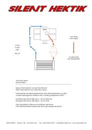
The fuel pressure regulator<br />
Rücklauf zum Tank<br />
SILENT HEKTIK Hansastr. 72b 59425 Unna Germany Tel. (+49) 02303-257070 Fax. (+49) 02303-257071 Page 16<br />
Tank<br />
Regler Bodys<br />
The fuel is put under pressure by <strong>the</strong> pumps and transported to <strong>the</strong> 1,0bar regulator at <strong>the</strong> right, riffled supply. From <strong>the</strong>re it is<br />
distributed left and right to <strong>the</strong> bodies. Both PTFE-ducts have to be as short as possible and equal in <strong>the</strong>ir length. The reflux to <strong>the</strong><br />
tank is <strong>the</strong> left, riffled tube, which comes out of <strong>the</strong> regulator.<br />
The fuel pressure regulator has to be assembled on <strong>the</strong> pickup-basesheet. The o<strong>the</strong>r drillings on <strong>the</strong> basesheet are ment <strong>for</strong> a<br />
dynamo regulator and a capacitor <strong>for</strong> <strong>the</strong> emergency running without <strong>the</strong> battery.<br />
Fuelpumps are not able to suck in, that is why <strong>the</strong>y always have to be assembled under <strong>the</strong> fuel level (tank). Fuel pumps are not safe<br />
<strong>for</strong> a dry running. A running without fuel will destroy <strong>the</strong>mvery fast. At <strong>the</strong> very first start one tube has to be loosened of <strong>the</strong> body<br />
<strong>for</strong> a fast de-aeration of <strong>the</strong> fuel system. Beware of <strong>the</strong> fuel stream.<br />
The intake filter in front of <strong>the</strong> pump(s) is made of Bosch-plastic. The compression filter behind <strong>the</strong> pump and in front of <strong>the</strong><br />
compression regulator has a Sinter-matal element. Please pay attention to <strong>the</strong> direktion of <strong>the</strong> flow.<br />
Tank<br />
Pumpen müssen<br />
unterhalb des Tanks<br />
montiert sein<br />
Düse<br />
Düse<br />
Filter<br />
2 1<br />
4<br />
Motor<br />
Regler<br />
Pumpe_A<br />
Pumpe_B<br />
SILENT HEKTIK<br />
Hydraulik 912 Twin<br />
Blau drucklos Rot 1,0 bar<br />
3. Vers. 27.07.2008<br />
Fuel pumps must be mounted under <strong>the</strong> fuel level (tank). Blue without pressure - red 1,0bar fuel pressure<br />
3<br />
Düse<br />
Düse<br />
Filter<br />
Pumpe
The Intake<br />
ASSEMBLY INSTRUCTIONS FOR THE ICM<br />
To get <strong>the</strong> best adjustment possible <strong>for</strong> each type of aircraft, <strong>the</strong> original intake manifold is still used. It is very flat and<br />
that is why <strong>the</strong>re is no need to change something at <strong>the</strong> cowling. The carburettor with a carburator flange is no more<br />
required. Instead <strong>the</strong> body is assembled directly. Please pay attention to an excellent sealing to secure a solid idling. The<br />
intake manifold is available in a diameter of 50mm, 60mm and 72mm. The 50mm version is <strong>the</strong> best standard solution.<br />
The injection jet holder has to be mounted between <strong>the</strong> cylinder head and <strong>the</strong> intake manifold. Again please pay attention<br />
to a good sealing on account of <strong>the</strong> idling. The ignition cables should have <strong>the</strong> greatest possible distance to <strong>the</strong> motor<br />
temperature sensor and <strong>the</strong> throttle position sensor. There are two vacuum supplies <strong>for</strong> <strong>the</strong> syncronisation of <strong>the</strong><br />
throttle and two bypass-channels with an screw <strong>for</strong> <strong>the</strong> micrometer adjustment.<br />
The Motor-Temperatur-Sensor<br />
The Motor-Temp.-Sensor should be located on backwards valvecover.<br />
There<strong>for</strong>e a M10x1mm thred must be mashined and<br />
<strong>the</strong> sensor srewed and glued in it.<br />
SILENT HEKTIK Hansastr. 72b 59425 Unna Germany Tel. (+49) 02303-257070 Fax. (+49) 02303-257071 Page 17
ASSEMBLY INSTRUCTIONS FOR THE ICM<br />
The ignition coils<br />
The four ignition coils can be placed in <strong>the</strong>ir original position. As a matter of principle <strong>the</strong> ignition cables should be as short as<br />
possible and in a maximum distance to <strong>the</strong> sensor cables. The o<strong>the</strong>r, better position of <strong>the</strong> coil is in front of <strong>the</strong> engine. In this<br />
case <strong>the</strong> high tension cable are short as possible.<br />
Lambda - Measurement<br />
The high tension leeds must be istalled in <strong>the</strong> best way and cut to <strong>the</strong><br />
right length. Be<strong>for</strong>e crimping <strong>the</strong> connectors <strong>the</strong> U-wire must be placed<br />
to <strong>the</strong> end. The wire connencts <strong>the</strong> stainless steel core with <strong>the</strong><br />
connector.<br />
For an adjustment of <strong>the</strong> different 912 configurations, a Lambda-measuring method is used. It is useful to measure at two differe nt<br />
cylinders, e.g. on <strong>the</strong> left in front and on <strong>the</strong> right at <strong>the</strong> back. Different exhaust systems are causing mostly different fillings, which<br />
need to be adjusted to <strong>the</strong> different fuel amount. An optimum would be four equal fillings, which can only be achieved with a 4-in-1<br />
tuned exhaust pipe.<br />
For a load from 0% up to 33% we recommend a Lambda from 0,94La up to 0,98La. For a load from 33% up to 70% we recommend a<br />
Lambda between 0,90La – 0,94La. For <strong>the</strong> two highest loads (full throttle) we recommend a Lambda from 0,85La up to 0,88La.<br />
SILENT HEKTIK Hansastr. 72b 59425 Unna Germany Tel. (+49) 02303-257070 Fax. (+49) 02303-257071 Page 18
DK Sensor A<br />
Motor Temp. A<br />
Luft Temp. A<br />
ICM_A<br />
ASSEMBLY INSTRUCTIONS FOR THE ICM<br />
Düse<br />
Düse<br />
Spule<br />
Spule<br />
Pumpe_A<br />
Hauptschalter Plus Batterie Minus<br />
2 1<br />
4<br />
Motor<br />
Pumpe_B<br />
Backup<br />
The wiring diagram <strong>for</strong> <strong>the</strong> D_ICM. Two ICM´s work redundand and can be tested indepandently with <strong>the</strong> schwiches.<br />
Düse<br />
Düse<br />
SILENT HEKTIK Hansastr. 72b 59425 Unna Germany Tel. (+49) 02303-257070 Fax. (+49) 02303-257071 Page 19<br />
3<br />
Spule Spule<br />
SILENT HEKTIK<br />
Rotax 912 Twin wiring<br />
M<br />
DK Sensor B<br />
Motor Temp. B<br />
Luft Temp. B<br />
ICM_B<br />
Backup<br />
4. Version<br />
M 30.04.2008
ASSEMBLY INSTRUCTIONS FOR THE ICM<br />
ICM Bodys and fuel pressure regulator on <strong>the</strong> R1200GS motor. The Teflon fuel tubes must have <strong>the</strong> same length.<br />
Wiring diagram <strong>for</strong> <strong>the</strong> D_ICM : two ICM´s work redundant and can be switched <strong>for</strong> testing or <strong>for</strong> single operation<br />
SILENT HEKTIK Hansastr. 72b 59425 Unna Germany Tel. (+49) 02303-257070 Fax. (+49) 02303-257071 Page 20
ASSEMBLY INSTRUCTIONS FOR THE ICM<br />
The fuel pressure regulator<br />
Ignition coils<br />
The original pencil coils can<br />
be used with <strong>the</strong> ICM.<br />
But important is a special<br />
d-well control and a special<br />
installation like to see in<br />
<strong>the</strong> two diagrams.<br />
The original coil ernegy is<br />
very less. Coldstart problem<br />
happend ofen.<br />
For max. per<strong>for</strong>mance and<br />
best coldstart our powercoils<br />
are requiert.<br />
Pencil coil wiring diagram<br />
<strong>for</strong> <strong>the</strong> running with one<br />
ICM box.<br />
A bad connection on pin_2<br />
can make bad coldstart and<br />
problems at iddling.<br />
Pencil coil wiring diagram<br />
<strong>for</strong> <strong>the</strong> running with two<br />
ICM boxes.<br />
The fuel is put under pressure by <strong>the</strong> pump and transported to <strong>the</strong> 3,3bar regulator at <strong>the</strong><br />
lower, riffled supply. From <strong>the</strong>re it is distributed left and right to <strong>the</strong> bodies. Both Teflon-ducts<br />
have to be as short as possible and equal in <strong>the</strong>ir length. The reflux to <strong>the</strong> tank is <strong>the</strong> smooth<br />
6mm tube, which comes out of <strong>the</strong> regulator. The 3mm tube at <strong>the</strong> end is not important now.<br />
Its task is <strong>the</strong> pressure compensation of <strong>the</strong> membrane.<br />
Fuelpumps are not able to suck in, that is why <strong>the</strong>y always have to be assembled under <strong>the</strong> fuel<br />
tank. Beside, fuel pumps are not safe <strong>for</strong> a dry running. A running without fuel will destroy<br />
<strong>the</strong>m. At <strong>the</strong> very first start one tube has to be loosened of <strong>the</strong> body <strong>for</strong> a fast de-aeration of<br />
<strong>the</strong> fuel system. Beware of <strong>the</strong> fuel stream.<br />
The intake filter in front of <strong>the</strong> pump should be made of Bosch-plastic. The compression filter<br />
behind <strong>the</strong> pump and in front of <strong>the</strong> compression regulator has a Sinter-metal element. Please<br />
pay attention to <strong>the</strong> direktion of <strong>the</strong> flow.<br />
SILENT HEKTIK Hansastr. 72b 59425 Unna Germany Tel. (+49) 02303-257070 Fax. (+49) 02303-257071 Page 21
fuel cock<br />
Hose connection <strong>for</strong> <strong>the</strong> return hose<br />
eventually equipped with a return-valve<br />
fuel cock fuel cock<br />
ASSEMBLY INSTRUCTIONS FOR THE ICM<br />
single-fuel cock-version<br />
two-fuel cock-version<br />
fine-filter<br />
fine-filter<br />
fine-filter<br />
fine-filter<br />
pump block<br />
pump block<br />
SILENT HEKTIK Hansastr. 72b 59425 Unna Germany Tel. (+49) 02303-257070 Fax. (+49) 02303-257071 Page 22<br />
single cylinder version<br />
twin-cylinder-version<br />
throttle body<br />
throttle body<br />
throttle body<br />
SILENT HEKTIK<br />
Risk of fire and poisoning !<br />
Caution fuel !<br />
Hydraulic ICM_05<br />
M<br />
5. Versuch<br />
M 24.10.2001
16A Sicherung Zündschloß<br />
schwarz<br />
schwarz<br />
ASSEMBLY INSTRUCTIONS FOR THE ICM<br />
ICM_Box 06A<br />
rot<br />
blau<br />
25<br />
14<br />
13<br />
1<br />
Denso-La.<br />
Denso-La.<br />
weiß<br />
blau<br />
weiß<br />
12V<br />
Luftventil - Plus<br />
Luftventil - Minus<br />
blau<br />
optional<br />
Batterie<br />
Minus an Motorblock<br />
weiß<br />
blau<br />
braun<br />
blau<br />
1,0 qmm<br />
1,5 qmm<br />
2.Düse +<br />
2.Düse -<br />
2.Düse +<br />
2.Düse -<br />
SILENT HEKTIK Hansastr. 72b 59425 Unna Germany Tel. (+49) 02303-257070 Fax. (+49) 02303-257071 Page 23<br />
1<br />
2<br />
1<br />
2<br />
VORSICHT Hochspannung, Gefahr !<br />
Motor-T<br />
Luft-T<br />
Ein Pickup-Version auf linken Kanal<br />
schwarz<br />
grün<br />
braun<br />
rot<br />
rot<br />
rot<br />
rot<br />
gelb<br />
rot<br />
grün-gelb<br />
1<br />
2<br />
1<br />
2<br />
schwarz<br />
Drossel-Poti<br />
E-Ventil<br />
E-Ventil<br />
rot<br />
SILENT HEKTIK<br />
Zündspule<br />
Zündspule<br />
Benzin-Pumpe<br />
rot<br />
schwarz<br />
Pickup<br />
Pickup<br />
1<br />
3<br />
Anschlußplan ICM_07<br />
M<br />
12. Version<br />
M 07.07.2009<br />
Linker Rechts Linker Rechter<br />
Linker Rechter<br />
Kanal Kanal Kanal Kanal Kanal<br />
blau<br />
grau<br />
rot<br />
Farben rot blau gelb grün braun schwarz grau weiß grün-gelb Links Rechts<br />
Colors red bleu yellow green braun black grey white green-yellow left right
ASSEMBLY INSTRUCTIONS FOR THE ICM<br />
Member of:<br />
ADRESSE :<br />
:<br />
:<br />
:<br />
TEL-NUMBER :<br />
FAX-NUMBER :<br />
HOMEPAGE :<br />
SHIPPING :<br />
SILENT HEKTIK<br />
HANSASTR. 72B<br />
D-59425 UNNA<br />
GERMANY<br />
+49-2303-257070<br />
+49-2303-257071<br />
WWW.SILENT-HEKTIK.COM<br />
WORLDWIDE<br />
SILENT HEKTIK Hansastr. 72b 59425 Unna Germany Tel. (+49) 02303-257070 Fax. (+49) 02303-257071 Page 24