Create successful ePaper yourself
Turn your PDF publications into a flip-book with our unique Google optimized e-Paper software.
Blending Precision Floor Vibration Control with a Commitment to ManufacturingSECTION5Page 67PneumaticVibration Isolatorsfor OEMApplicationsGimbal Piston IsolatorsAir VibrationIsolation Systempage 68CSP ®Compact Sub-HertzPendulum VibrationIsolation Systempage 69MaxDamp ®Vibration IsolationSystempage 70SECTION6Page 71Electro-Damp ®Active Vibration IsolationSystemsElectro-Damp ® IIActive Pneumatic VibrationDamping Systempage 72PEPS II ®Digital Precision Electronic Positioning Systempage 74AccuDock Precision KinematicDocking Systempage 76SECTION7Page 77Magnetic FieldCancellationMag-NetX Magnetic Field Cancellation page 78SECTION8Page 81AcousticEnclosures &PrecisionStructuresSECTION9Page 8583-500 SERIESMulti-Purpose Acoustic Enclosurepage 82SECTION10Page 91Full Size “Walk-In”Acoustic Enclosurepage 83Acoustic Enclosure& Vibration IsolationSystempage 83Electropolished StainlessSteel Acoustic Enclosurewith Integrated VibrationIsolationpage 83Custom Structures page 83ManufacturingCapabilitiesTechnicalBackgroundwww.techmfg.com • 978-532-6330 • 800-542-9725 (Toll Free) • Fax: 978-531-8682 • sales@techmfg.com
Resource Guide 12TMResource Guide 12 presents<strong>TMC</strong>’s precision floor vibration isolationsystems from simple, desktop isolatedmicroscope bases, to any size optical top,to sophisticated active, inertial vibrationcancellation systems featuring piezo -electric actuators and digital controllers.Our latest innovations includeSTACIS 2100, STACIS ® iX SEM-Base ,STACIS ® iX Stage-Base , STACIS ® iX LaserTable-Base ,and Mag-NetX magnetic field cancellation systems.<strong>TMC</strong> is the leader in precision floor vibration isolationtechnology. Our customers include major research centers,OEM and end-user semiconductor manufacturers, universityresearch laboratories, drug discovery companies, andnanotechnology labs.With few exceptions, everything in Resource Guide 12has been designed and manufactured at <strong>TMC</strong>. With verticallyintegrated manufacturing, we can make complex mechanicalstructures quickly and cost effectively. No time is lost inmisinterpreting specifications and quality expectations.Many of our products are custom manufactured forOEM and end users. One of the major advantages of makingeverything at <strong>TMC</strong> is that tools such as 3D engineeringmodels can go directly to our factory floor withoutmissteps and delays.PRECISIONVIBRATION ISOLATIONSYSTEMS<strong>TMC</strong>’s headquarters and state-of-the-artmanufacturing facility are located in our dedicated80,000-square-foot (7,450 square meters) buildingin Peabody, Massachusetts.<strong>TMC</strong> is now part of AMETEK,a leading global manufacturer ofelectronic instruments and electromechanicaldevices.<strong>TMC</strong> joins AMETEK as part ofthe Ultra Precision Technologiesdivision of AMETEK EIG. UltraPrecision Tech nologies is a pioneerin the development of ultra precisionmeasurement instruments and a global leader in ultraprecise machine tools and manufacturing systems for thesemiconductor, photovoltaic, nanotechnology, military,defense, and ophthalmic lens markets.AMETEK, Inc. is a leading global manufacturer ofelectronic instruments and electromechanical devices.AMETEK has approximately 11,600 colleagues working atmore than 100 manufacturing facilities and more than 100sales and service centers in the United States and aroundthe world.Now part of AMETEK, we remain <strong>TMC</strong>. The same peoplein the same location committed to pioneering our field bydesigning and manufacturing the most advanced precisionfloor vibration isolation systems commercially available.<strong>TMC</strong>: ISO 9001 CertifiedISO 9001:2008C E R T I F I E D<strong>TMC</strong> is ISO 9001:2008 certified, the most comprehensive of the ISO standards. <strong>TMC</strong> passed itsregistration audit with no “findings,” a feat accomplished by fewer than 10% of companies audited.In fact, to date, we have had no findings during any of our annual ISO 9001 re-certification audits.For <strong>TMC</strong>, this is an acknowledge ment of a quality philosophy we have had since our founding.Since 1969, long before it became fashionable, we implemented a program of continuous productimprovement based on a fundamental oper ating premise...we wanted to exceed the expectationsof our customers.We invite you to challenge us with your demanding vibration application.www.techmfg.com • 978-532-6330 • 800-542-9725 (Toll Free) • Fax: 978-531-8682 • sales@techmfg.com
STACIS ®1Active Piezoelectric Vibration Cancellation Systemswww.techmfg.com • 978-532-6330 • 800-542-9725 (Toll Free) • Fax: 978-531-8682 • sales@techmfg.com1
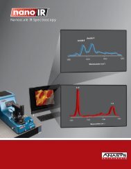
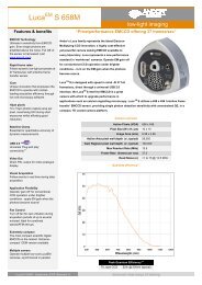
EFeatures & Benefits• Provides greater than 90% isolationat frequencies greater than 2 Hz, Ivertical and horizontal O• Reduces fab floor construction costs,allows tools to be installed in higher Ivibration environments• Active bandwidth, 0.6 Hz to 150 Hz• Recommended by many toolmanufacturers• 6 degree-of-freedom active hardmount design, no soft air suspension6 active degrees-of-freedomCI• Installs easily, robust control systemrequires minimal or no on-sitecompensation• A point-of-use solution that iscompatible with all internal toolvibration isolation systems• Ensures tool vibration criteriawill be met as vibrationlevels increase over time• Uses <strong>TMC</strong>’s patented STACIS ®technology to cancel vibrationusing piezoelectric actuators• Enables older and noisier floors toaccommodate state-of-the-art tools• Compatible with various floor heightsand sub-floor geometries in fabs• Increases throughput, qualityand yieldSTACIS ® Ordering Chart<strong>Catalog</strong> Number Description Pricing21-301-01 STACIS, 3-mount, low capacity Contact21-301-02 STACIS, 3-mount, medium capacity <strong>TMC</strong>21-301-03 STACIS, 3-mount, high capacity21-401-01 STACIS, 4-mount, low capacity21-401-02 STACIS, 4-mount, medium capacity21-401-03 STACIS, 4-mount, high capacity1iThe result STACIS ® 2100 on a “riser” installed under a<strong>TMC</strong> platform in a 36" tall raised floor4DC-2000 Digital ControllerGENERAL SPECIFICATIONS (may vary depending on configuration)Performance SpecificationsDimensions, Environmental and UtilityRequirementsAnalog inputs/outputs 16 channels(16/14 bit)Digital inputs/outputs 16Sampling rate6.5 KHz nominalFront panelTwo-line LCDwith soft menu keysBNC input and outputfor signal monitoringTwo RS-232communication ports(second port on rear)Tri-color system status lampPhysicalSingle ReTMA rack unitheight x 15 in. deepPower90-240 VAC, 50-60 Hz,600 watts max.OtherPower connector forsupport of external devicesActive degrees of freedom 6Active bandwidthNatural frequency0.6 to 150 HzPassive elastomer: 18 Hzeffective active resonantfrequency: 0.5 HzIsolation above 2.0 Hz > 90 %Settling time after a 10 lb (4.5 kg) 0.3 secstep input (10:1 reduction)Internal noise 2:1Number of isolators 3 or 4Maximum displacement480 µ in. (12 µm)Stiffness (1,000 lb/454 kg mass) 40,000 lb/in.(typical middle capacity isolator) (73 x10 5 N/m)Magnetic field emitted< 0.02 micro-gaussbroadband RMSIsolator size 11.75 in. (w) x 12.5 in. (d) x 10.8 in. (h)(300 x 320 x 275 mm)Isolator weight 75 lb (34 kg)Controller size 19 in. (w) x 15 in. (d) x 1.75 in. (h)(483 x 381 x 44 mm)Temp., operating 50° to +90°F (10 to 32°C)Temp., storage -40° to 255°F (-40 to 125°C)Humidity, 30 - 60%operatingPower required 100, 120, 230 or 240 volts;50/60 Hz; < 600 watts,Ce compliantFloor< 480 µ in. (12 µm) below 10 HzdisplacementOptions: <strong>TMC</strong> laminated, stainless steel platforms,frames, and “risers,” leveling devices,earthquake restraints, and lifthoodswww.techmfg.com • 978-532-6330 • 800-542-9725 (Toll Free) • Fax: 978-531-8682 • sales@techmfg.com3
(continued)Quiet Island ®Sub-Floor Platforms and SupportsSemiconductor manufacturingfactories (fabs) incorporate asystem of raised false floors toaccommodate complex facilitiesrequirements (plumbing, electri -cal cables, gas piping, etc.) andto maintain strict cleanlinessstandards. Such floors presenta chal lenge to the installationof extremely vibration-sensitiveproduction, inspection, andmetrology equipment. Theraised floors cannot providethe necessary quiet vibrationenvironment for such tools.<strong>TMC</strong>’s Quiet Island ® is an innova -tive solution that replaces a section ofthe raised floor area with a “Quiet Island”anchored to the sub-floor below. TheQuiet Island consists of a special platformcombined with a dedicated supportstructure, the nature of which dependsupon the application.PlatformThe platform is a <strong>TMC</strong> designed andmanufactured 4 inch (100 mm) thicklamination of steel plates sandwichedaround a lightweight, incompressible,damped core material. The layeringeffect of rigid steel plates and core, epoxybonded into a seamless, stainless steelpan provides an extremely high level ofstiffness and structural damping. Thelarge cross-section and steel content yielda very high level of overall rigidity. Thetop and sides are a continuous, one-piece,stainless steel shell to preservecleanliness, appearance and integrity.Platform SupportsDepending on the specific applicationrequirements, the platform supports areeither a rigid, non-resonant support standor a STACIS ® 2100 Active VibrationCancel la tion System. If the sub-floormeets the vibration criteria of the tool inquestion by a reasonable margin, simplysupporting the tool with a support thatdoes not ampli fy vibration is sufficient.To achieve this, <strong>TMC</strong> has designed a familyof ultra-rigid support stands for a rangeof floor heights and sub-floor access holerequirements. Typically tripods, quadstandsor square cross-section stands,these attach directly to the sub-floorand platform.However, if the sub-floor does not meetthe tool vibration criteria, a “point-of-use”vibration isolation system must beemployed. STACIS 2100 is the idealchoice. STACIS 2100 is compatible withall tool internal vibration isolation systems(ask for our Stacking Active on Activewhite paper). In addition, it provides themost vibration isolation across thewidest frequency range commerciallyavailable.Rigid-DampedTripod (no platformrequired)And, the “hard-mount” design is extremelystiff so that there is no stability concernfor tall, top-heavy tools.The rigid stands and STACIS 2100supports are interchangeable and fieldupgradable. Together, they provide thecomplete solution for supporting sensitivetools in a fab raised-floor environment.Other Quiet IslandConfigurationsThe many types of raised floors andinstallation challenges has led <strong>TMC</strong> todevelop a number of innovative andunusual solutions. Among these are<strong>TMC</strong>’s patented Rigid-Damped Tripod.If you have an unusual raised-floorchallenge, chances are we already have aproven solution. Please contact one ofour Application Engineers to learn more.A version of our Rigid Quiet Island ® meets the moststringent water scanner floor stiffness specifications.4 www.techmfg.com • 978-532-6330 • 800-542-9725 (Toll Free) • Fax: 978-531-8682 • sales@techmfg.com
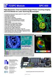
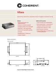
APPLICATION NOTEImpact of Vibration on Advanced Immersion Lithography(actual customer supplied data)1The 45 nanometer line-width test patterns shown were produced with anadvanced Immersion Lithography System manufactured by Amphibian Systemsand installed at SEMATECH in Austin, Texas. Variation between the images is dueto the effect of seismic vibration on the photolithography process. The imagesshown were obtained using a scanning electron microscope.45 nm L/S45 nm L/SWithout STACIS ® ...Best pattern obtained on eitherthe elastomer or rigid versionof original pedestal.With STACIS ® ...Pattern achieved with STACISactive vibration isolation.The tool was initially installed on a steel and concrete plinth with a steel support structure which incorporatedcommercial elas tomer vibration isolation pads. This pedestal did not achieve the tool’s specified vibration criteria andpattern quality was poor.In an attempt to reduce vibration, the elastomer pads were effectively shorted out with metal shims leading toa more rigid, non-resonant structure but this resulted in little im provement. The vibration criteria were not met witheither version of the pedestal and pattern quality remained poor.*VIBRATION LEVELSSTACIS and Non-STACIS PedestalsRigid version ofpedestal (white)Elastomer version ofpedestal (green)STACIS version ofpedestal (blue)125 µin/sec tool spec (red)The plinth support structure wasremoved and retrofitted with a STACIS ®Active Piezoelectric Vibration Cancell -ation System. The STACIS mounts wereplaced directly beneath the existingplinth. Supporting the tool on STACISresulted in a dramatic reduction ofoverall seismic vibration levels andachievement of the manu fac turer’s floorvibration specification. More importantly,STACIS provided a dramatic improve -ment in pattern quality.*Vertical Axis Data shownPhotos, images, and vibration data courtesy of SeMATeCH.www.techmfg.com • 978-532-6330 • 800-542-9725 (Toll Free) • Fax: 978-531-8682 • sales@techmfg.com5
(continued)65 Series STACIS ® Floor Platform supporting an Omicron Multiprobe Scanning Tunneling Microscope (STM) with nanometer scaleresolution at the Max Planck Institute in Dresden, Germany.6 www.techmfg.com • 978-532-6330 • 800-542-9725 (Toll Free) • Fax: 978-531-8682 • sales@techmfg.com
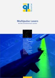
65 SERIESFloor Platformwith STACIS ®For conventional lab floors, isolatingbuilding floor vibration fromlarge, tall tools presentsan ergonomic challenge.Placing the isolatorsdirectly beneath thetool may raise the toolto an impractical height.Furthermore, conventional air isolatorsare unstable when placed close togetherunder a tall, top-heavy payload.<strong>TMC</strong>’s 65 Series Floor Platforms solvethis dilemma. By combining our StainlessSteel Platforms (see page 4 discussion)with a unique “lifthood” design, ourisolators “cradle” the platform allowingthe tool to be lifted a minimal distanceabove the floor. And, because the isolatorsare not integrated into the platform, theplatform may be custom designed to matchthe tool footprint or any desired shape.<strong>TMC</strong> floor platforms are configured withour STACIS ® Active Piezo electric Isolators.The advantages of STACIS include:• STACIS piezoelectric isolators sufferno ill effects from tall, top-heavypayloads. There’s no danger ofgravitational instability.• Instruments mounted on floorplatforms (TEMs, STEMs, STMs,SPMs, etc.) are among the mostvibration-sensitive tools made.STACIS provides the best vibrationisolation commercially available withno low-frequency amplification.• Instruments requiring isolationtypically incorporate an internal,built-in vibration isolation system.This system is generally a low-frequencyair isolator which, in general, shouldnot be supported by another lowfrequencyair isolation system.STACIS is compatible being “stacked”beneath any tool’s internal isolationsystem (ask for our SupportingNEW From <strong>TMC</strong>!Active Electro-Pneumatic VibrationIsolation Systems on PlatformsSupported by STACIS ® ‘Hard-Mount’Piezoelectric Isolation Systemswhite paper).<strong>TMC</strong> works closely with instrumentmanufacturers to ensure that our platformdesign meets the instrument’s footprint,structural, and utility require ments.We have successfully isolated hundredsof different instruments and are oftenalready familiar with the tool require ments.In most instances, you need only providethe tool manufacturer and model for us torecommend a solution.Note: For Scanning electron Microscopes(SeMs), <strong>TMC</strong> has developed a dedicatedversion of our STACIS Floor Platform.See STACIS ® iX SeM-Base on page 12.1How to Order:1. Identify the equipment or instrument modeland configuration.2. Confirm the type of floor you have – conventionaltiled lab floor, wooden beam and planks, etc.3. Tell us if the instrument manufacturer has made apre-installation site survey of the vibration level.In most cases, a standard floor platform will berecommended. We may recommend taking ourown site vibration measurements and look at thespecial conditions involved.STACIS ® 65 Series Floor Platform supporting a JEOL JEM-2100F TransmissionElectron Microscrope (TEM).www.techmfg.com • 978-532-6330 • 800-542-9725 (Toll Free) • Fax: 978-531-8682 • sales@techmfg.com7
(continued)A Cameca NanoSIMS 50L on a <strong>TMC</strong> 65 Series Floor Platform supported by STACIS ® isolators.This tool is a 5,000-pound secondary ion mass spectrometer with a spatial resolution of 50 nanometers.Photo courtesy of the Planetary and Space Sciences Research Institute (PSSRI) at The Open University, Milton Keynes, U.K.8 www.techmfg.com • 978-532-6330 • 800-542-9725 (Toll Free) • Fax: 978-531-8682 • sales@techmfg.com
APPLICATION NOTESTACIS ® as a Microseismic Shaker1Equipment manufacturers can use STACIS ®to generate micron-level floor vibrationsimulating real world floor activity todevelop tool vibration criteria.Semiconductor equipment makers, electron microscopemanufacturers, and other precision tool makers struggleto develop meaningful floor vibration criteria for theirinstruments. These criteria can be derived eithertheoretically or empirically. Theoretical calculations areextremely complex and are often impractical or do notreflect actual tool sensitivity because of the manyvariables that cannot be easily modeled. Floor vibrationcriteria arrived at empirically are typically based onSTACIS ® 2100 is used as an isolation system/micron-levelgathering tool performance information from a wide range shaker within <strong>TMC</strong>’s own factory to test performance ofof installations represented by various floor vibration levels.other <strong>TMC</strong> vibration isolation products.These floor vibration levels and the corresponding tool performance are used to create an upper limit of vibrationamplitudes over a frequency spectrum that represents floor vibration levels that will result in acceptable toolperformance. Both of these approaches are extremely difficult, time consuming, and do not result in a precisevibration specification for the tool.STACIS ® 2100 offers acompletely unique andnovel way to approach thedevelopment of tool vibrationcriteria. STACIS, which isnormally operated as a floorvibration isolation/cancellationsystem, can also be operated to provide micron-levelshaker input. This shaker signal can be white noise,discrete frequency, or a sine-swept wave-form. STACIScan provide independent or combined X, Y and Z axisvibration input. As a shaker, STACIS can be run to sim -ultaneously cancel building floor vibrations pro vidinga quiet foundation while superimposing on this thedesired frequency and amplitude vibration spectrumrequired to test tool performance. No other shakersystem can control inputs down to such small ampli tudes.No other shaker system can isolate ambient floor vibrationwhile simultaneously providing a controlled vibrationfrequency spectrum. The vibration generated at theSTACIS digital controller at extremely low amplitudesis not corrupted by ambient building floor vibrationsat the test site.Complete working toolscan be mounted on a STACISisolation/shaker system, andthe STACIS vibration amplitudescan be adjusted as overall toolperformance is evaluated. Thetool can be excited at givenfrequencies or given bands of frequencies to determinethe exact amplitude/frequency relationship of vibrationinput that limits overall tool performance. The result isan overall tool vibration criteria level that correspondsto the exact vibration level at which the tool can provideoptimal performance. This testing can be completedrela tively quickly and easily – without shipping tools tocustomer sites and waiting for large amounts of fielddata or relying on questionable modeling information.Contact <strong>TMC</strong> or your local sales representative toacquire a STACIS ® 2100 system for use as a shaker fortesting your sensitive equipment in a controlledvibration environment.www.techmfg.com • 978-532-6330 • 800-542-9725 (Toll Free) • Fax: 978-531-8682 • sales@techmfg.com9
(continued)STACIS ® supporting the end chambers of a prototype LIGOinterferometer at the California Institute of Technology. These arethe most precise instruments ever made – capable of measuringdistances of less than 10 -18 meters.A STACIS ® System, incorporating a non-ferromagnetic, highly damped,aluminum platform, provides a second stage of vibration isolation for aBruker BioSpin 600 MHz NMR Spectrometer. Photo courtesy of BukerBioSpin and Memorial Sloan Kettering Cancer Center.The Nikon FX-21S LCD Stepper incorporates an advanced version of <strong>TMC</strong>’s STACIS ® for the ultimate in vibrationcancellation. The rigid mounts yield faster settling times in response to motion resulting in higher throughput.10 www.techmfg.com • 978-532-6330 • 800-542-9725 (Toll Free) • Fax: 978-531-8682 • sales@techmfg.com
iXIntegrated Active Piezoelectric VibrationCancellation Systems22www.techmfg.com • 978-532-6330 • 800-542-9725 (Toll Free) • Fax: 978-531-8682 • sales@techmfg.com11
Optical iX Tops, Breadboards, & SupportsSTACIS iXSEM-Base Active Piezoelectric Vibration Cancellation Floor Platformfor Scanning Electron MicroscopesNEW From <strong>TMC</strong>! U.S. Patent No. 5,660,255 Other Patents PendingIAVE ingiSTACIS ® iX SEM-Base activevibration cancellation floor platformsystem is designed for use withscanning electron microscopes (SEMs).SEMs are among the most vibrationsensitive tools made, and theseprecision instruments typically incor -porate an internal vibration isolationsystem. SEM-Base is compatiblewith all internal SEM vibrationisolation systems.SEM-Base is a compact, cost-effectivealternative to our 65 Series STACIS ® 2100Floor Platform (page 7). It incor poratesSTACIS technology but has a much s(The result6 active degrees-of-freedomC * 2,150 lb. (980 kg) payload with simulated floor vibration at VC-E(125 micro-inches per second, 3 microns per second)Transmissibility *Ismaller footprint andinstalls easily with minimal tuning.I With vibration cancellation startingO below 1 Hz, SEM-Base featuresextended stroke piezoelectric actuatorsIand damped, powder-coated steel platesthat sandwich four isolators and <strong>TMC</strong>’sDC 2000 digital controller. The systemis only 6.5" tall, measures 35.5" x 44.5",weighs approximately 500 pounds, cansupport 900 to 2,500 pounds, and hasno soft air suspension. s(commercial SEMsI• Load capacity: 900 - 2,500 lb.A• Vibration cancellation starts below 1 Hz• Extended stroke piezoelectric actuators, 3up to 60 micronsI• 6 active degrees-of-freedomLA• Installs easily, minimal tuning required V3 • Compatible with all internal tool vibration Eisolation systemsL • No soft air suspension6 active degreV • Simple, robust, and cost-effective II E • Optional casters allow easy portability,CA no lifting required3 6 • active Ask about degrees-of-freedomour SEM-Lift SystemNfor installationISL COVE NAS6 active degrees-of-freedomI OCANS O 12 www.techmfg.com • 978-532-6330 • 800-542-9725 (Toll Free) • Fax: 978-531-8682 • sales@techmfg.com AFeatures• Incorporates patented STACIS ® technology• Active inertial vibration cancellation system• 35.5 x 44.5 x 6.5 inches, fits most6.5 in. (165 mm)nominal
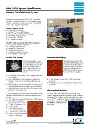
APPLICATION NOTEBefore and After Images, Zeiss Auriga FIB-SEMon STACIS ® iX SEM-Base with Mag-NetX (actual customer supplied data)2BeforeAfterMagnetic fielddistortionFloor vibrationdistortionTThe imageTThe image on the right was taken immediately after the systems were powered-on.The before and after photos above are actual imagestaken from a Zeiss Auriga FIB-SEM installed in a nonidealenvironment. The image on the left was takenwith the newly installed e <strong>TMC</strong> STACIS® iX SEM-BaseFloor Platform and Mag-NetX Magnetic FieldCancellation systems powered-off. The image on theright was taken immediately after both active systemswere powered-on.TTAAPPSMfwww.techmfg.com • 978-532-6330 • 800-542-9725 (Toll Free) • Fax: 978-531-8682 • sales@techmfg.comSM13f
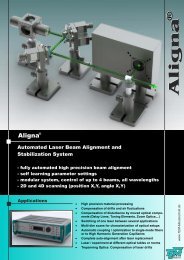
iX (continued)Ask about helpful options that will ensurea smooth SEM-Base installation.SEM-Lift Convertible Roll-Off CrateSEM-Base (shown with optional retractable casters) may beprovided with a convertible roll-off crate. The crate cover convertsto a sturdy ramp and the cover slats form a guide for the wheels.SEM-Lift is a safe and sturdy lifting device for scanning electronmicroscope (SEM) columns. It simplifies and speeds SEM-Base installation on a previously installed SEM column. SEM-Lift raisesthe column several inches allowing SEM-Base to be rolledinto place.14 www.techmfg.com • 978-532-6330 • 800-542-9725 (Toll Free) • Fax: 978-531-8682 • sales@techmfg.com
2STACIS ® iX SEM-Base Floor Platform isolating an FEI Helios NanoLab DualBeam SEM/FIB (top left), a JEOL JSM-6700F FieldEmission Scanning Electron Microscope (top right), an Hitachi S-3400N SEM (bottom left), and a Zeiss UltraPlus Field EmissionScanning Electron Microscope (bottom right).www.techmfg.com • 978-532-6330 • 800-542-9725 (Toll Free) • Fax: 978-531-8682 • sales@techmfg.com15
iX (continued)STACIS iXLaserTable-Base Hybrid Piezoelectric/AirActive Vibration Cancellation SystemIAVE NEW From <strong>TMC</strong>!U.S. Patent No. 5,660,255Other Patents Pending6 active degrees-of-freedomCIIAVEIOIA6 active degrees-of-CIIOIi<strong>TMC</strong> introduces STACIS ® iX Laser-Table-Base , the latest addition toour STACIS ® iX line of piezoelectricactive vibration cancel lation systems.LaserTable-Base offers an extraordinarylevel of improvement over existingtechnology in the amount of vibrationisolation attainable with anTheOpticalresultTable. Transmissibility *Typically, Optical Tables are supportedby low-frequency pneumatic vibrationisolation systems. Though very effectiveat isolating high frequencies, these passivesystems actually amplify vibration inthe critical 1 to 3 Hz range. Ltha1 to 3 Hz range.Ta Features• Incorporates patented STACIS ® technology• Active inertial vibration cancellation system• Vibration cancellation starts below 1 Hz• Extended stroke piezoelectric actuators,up to 60 microns• 6 active degrees-of-freedom• Consists of two isolation systems in seriesfor maximum vibration cancellation• Incorporates patented MaxDamp ® Air Isolators• Simple, robust, and cost-effective• Installs easily, minimal tuning required• Optional shelves for mounting equipmentunder the table• Includes <strong>TMC</strong>’s DC-2000 Digital ControllerThough very effective at isolating <strong>TMC</strong>’s STACIS ® technology overcomesthese limitations through a patentedtechnology which incorporatespiezoelectric actuators and inertialvibration sensors to cancel, not amplify,very low-frequency vibration.iThe result 16www.techmfg.com • 978-532-6330 • 800-542-9725 (Toll Free) • Fax: 978-531-8682 • sales@techmfg.com
LaserTable-Base combines these twotechnologies, air and STACIS ® , into oneintegrated cancellation system. Theresult is vibration cancellation at verylow frequencies and unprecedentedlevels of high-frequency isolation dueto the com bined effect of two isolationsystems in series.2Furthermore, STACIS ® iX improves uponthe original STACIS technology by theaddition of extended travel piezoelectricactuators (to accommodate even theworst floors) and an updated designthat signifi cantly lowers total cost.The upper pneumatic portion ofLaserTable-Base consists of patentedMaxDamp ® Air Isolators. The modulardesign allows for customizing the airsub system for specific applicationrequirements.Until recently, researchers desiring the quietest possible vibration environmentin a lab combined two independent products into a two-stage isolation system.This photo shows a 784 Series CleanTop ® Optical Top supported by Gimbal Piston Air Isolators. This air isolation system is, in turn, supported on a 65 Series FloorPlatform cradled with STACIS ® 2100 Isolators. LaserTable-Base now combinesthese two independent isolators into one integrated system, with improvedoverall performance. Vertical Transmissibility Horizontal Transmissibility ®www.techmfg.com • 978-532-6330 • 800-542-9725 (Toll Free) • Fax: 978-531-8682 • sales@techmfg.com17
iX (continued)STACIS iXStage-Base VFrame Mountable Active Hard-Mount PiezoelectricVibration Cancellation SystemNEW From <strong>TMC</strong>!U.S. Patent No. 5,660,255Other Patents Pending Aolating<strong>TMC</strong> introducesSTACIS ® iX Stage-Base ,a Frame Mountable ActiveHard-Mount PiezoelectricVibration V Cancellation System.Stage-Base is specificallydesigned to be built into advancedsemiconductor tools which incorporatehigh precision motorized X-Y stages.Such tools require extremely efficientvibration isolation. But, just as critical,these tools require that payloadmotion induced by the stage settlevery quickly so as not to adverselyimpact tool throughput.Stage-Base incorporates <strong>TMC</strong>’s patentedSTACIS ® technology to achieve extremelyefficient vibration isolation using piezoelectricactuators and a stiff suspension.<strong>TMC</strong> continues to apply advancing tech -nology to develop new solutions to thei The resultIAVE6 active degrees-of-freedomCIIOIchallenging demands thatsemiconductor tools place on theirvibration isolation systems. Stage-Baseprovides vibration isolation comparable toour STACIS active piezoelectric vibrationcancellation systems but is specificallydesigned to bethe primary isolationsystem incorporated inside the tool.Stage-Base features extended strokepiezoelectric actuators, fast settling timein response to stage motion, and ahard-mount suspension with no soft airsprings. It is available in 6 degrees-of-freedomand starts to isolate well below 1 Hz. Transmissibilityity * * 2,150 lb. (980) payload with simulated floor vibration atVC-E (125 micro-inches per second, 3 microns per second)SSettling TimeFeaturesA• Incorporates patentedSTACIS ® technology• Extended stroke piezoelectricactuators, up to 60 microns• Position S repeatability of payloadto within microns• Frame-mountable design• 6 active degrees-of-freedom• No feedforward required• Active inertial vibrationcancellation system• Fast settling time in responseto stage motion• No soft air suspension• Simple, robust, and cost-effective18 www.techmfg.com • 978-532-6330 • 800-542-9725 (Toll Free) • Fax: 978-531-8682 • sales@techmfg.com
Optical Tops, Breadboards, & Supports3Top photo courtesy of MetroLaser; bottom, NASA Goddard’s Advanced Interferometer and Metrology Lab (AIM)incorporates two 5' x 16' x 2' Invar CleanTop ® Optical Tops, each supported on a six-mount STACIS ® activepiezoelectric vibration cancellation system.www.techmfg.com • 978-532-6330 • 800-542-9725 (Toll Free) • Fax: 978-531-8682 • sales@techmfg.com19
Optical Tops, Breadboards, & SupportsCleanTop ®Epoxy-bondednylon 6 cup standard,under each hole(Optional: stainless steel304 alloy cups)Precision tapped holesrequire no wrench forscrew insertionUser-friendlyrounded cornersElectro-chemicallyetched alpha-numericgrid0.5 square inchcore cell areaSteel-to-steelbonding throughout,no plastic layersThree levels ofstructural dampingSidewalls of <strong>TMC</strong> tops are0.075 in. (2 mm) thick, damped,cold-rolled formed steel.<strong>TMC</strong>’s CleanTop ® SteelHoney comb Optical Top is theindustry standard. It provides thehighest core-density and smallesthoney comb cell area in an all-steelconstruction with the first, andstill best, spill-proof hole design.CleanTop, originally patented by<strong>TMC</strong> in the 1980s, has been refined toa new process that yields a cleaner,more precise, and more corrosionresistantset of tapped holes.Perhaps no single characteristicof an optical top is as crucial as itsstructural damping. <strong>TMC</strong>’s R&DDepartment is constantly evalua tingnew techniques and materials tomaximize structural damping per -formance. We are able to offer new,improved levels of performanceand added flexibility in specifyinga <strong>TMC</strong> top.Radius corners and non-magnetic topsare among the other improve mentsand additions to our product line.<strong>TMC</strong>’s CleanTop Optical Top isthe best method yet for providing aspill-proof optical top with unmatchedstruc tural performance. CleanTop isnow a standard feature of all <strong>TMC</strong>optical tops. Conven tional open coretops are no longer made by <strong>TMC</strong>.Our innovative CleanTopwas the firstspill-proof optical top. Its proprietarydesign involved capacitance dischargewelding a one-inch-long stainless steelor plated steel cup under each drilledhole prior to thread tapping. A keyelement is that the cups are individualand non-load bearing.The current process improves on theoriginal CleanTop design. Indi vidualCleanTop cups are now epoxy-bonded,not welded, under each tapped holeafter it is tapped and cleaned. Cups20 www.techmfg.com • 978-532-6330 • 800-542-9725 (Toll Free) • Fax: 978-531-8682 • sales@techmfg.com
are made from chemically resistantnylon 6, and stainless steel (304 alloy)cups are also available as as option.Holes are now tapped and countersunkprior to adding the cups to allow themachined top sheet to be thoroughlycleaned with open, rather than blind,holes prior to bonding. The top plateis processed through a custom <strong>TMC</strong>industrial cleaning center where a highpressure, high temperature cleaningsolution is forced through each threadedhole, completely clearing any machiningor tapping debris. Several rinse and drycycles ensure an essen tially “sterilized”top surface prior to bonding the cups.CleanTop ® represents anotherinnovation in <strong>TMC</strong>’s long optical toptradition of industry “firsts” including:• First spill-proof optical top(CleanTop).• First all-steel optical top.• First oil-free optical top.• First honeycomb core registeredto the tapped hole array.• First lightweightbreadboard withformed rather thandrilled holes.• First vacuumcompatibleoptical top.CleanTop features:• Structural construction,specifi cations, and integrity.• Liquid spills on the surface arecontained and cannot reach the top’shoneycomb core.• The core is completely clean and drywith no residual thread-cuttingoils to out-gas.General Chemical Resistanceof the Nylon 6 and StainlessSteel 304 Alloy Cups (optional)Nylon 6 304 StainlessSteelAromatic Solvents Excellent ExcellentAliphatic Solvents Excellent ExcellentHydrocarbons Excellent ExcellentGasoline & Oils Excellent ExcellentRefrigerants Excellent ExcellentChlorinated Solvents Fair ExcellentWeak Acids Good ExcellentStrong Acids Attacked ExcellentWeak Alkalines Excellent ExcellentStrong Alkalines Good ExcellentOxidizing Agents Attacked Excellent• Extremely clean tapped holes makescrew insertion smooth and simple.• Easy retrieval of small parts droppedinto the holes is assured.• Since no penetration of the core ispossible when dangerous chemicalsare used on the top’s surface, healthhazards will not occur by chemicalsreaching the core unnoticed.3www.techmfg.com • 978-532-6330 • 800-542-9725 (Toll Free) • Fax: 978-531-8682 • sales@techmfg.com21
Optical Tops, Breadboards, & Supports (continued)How To Select a <strong>TMC</strong> Optical Top1. Damping<strong>TMC</strong> offers three levels of structuraldamping, though not all levels are availablein each construction. Because thedamping mechanisms are expensive tomanufacture, it is prudent to specifyonly the level of damping required.All <strong>TMC</strong> damping levels incorporatebroadband dry damping. For a completedescription of broadband vs. tuneddamping, see page 104.Maximum Dry Damping<strong>TMC</strong>’s maximum dry damping pro videsa level of perfor mance unsurpassed inthe industry. It is recommended for themost demanding applications includingholography, interferometry, ultra - fastoptics, and spectroscopy. In addition, itis recommended in particularly noisyvibration and acoustic environments.For pulsed lasers and other noisegeneration equipment, it is especiallyhelpful. For complete specifications,see pages 101-105.Standard Dry DampingAn economical alternative forless sensitive applicationsincorporates our standarddry damping level. This broadbanddamping level provides a top withperformance characteristics that exceedthe majority of other manufacturers’highest performance levels. Peakcompliance levels for standard dampingexceed peak compliance levels of ourmaximum damping by a factor of four.Nominal Dry DampingThis damping level is not recommendedif sensitive work is being conducted onthe table. The nominal damping level isappropriate for general lab work whenthe main consideration is a rigid, flatmounting surface.Please refer to the Dry DampingPerformance Summary onpage 25 for more information.Major factors to consider whenselecting a <strong>TMC</strong> optical top:1. Level ofstructural damping2. Skin thickness3. Top thickness4. Environment5. Tapped-holeconvention(imperial vs. metric)2. Skin ThicknessThe vast majority of <strong>TMC</strong> opticaltops are available in a choice of twothicknesses: 3/16 in. (5 mm) and 1/8 in.(3 mm). For structural performancereasons, the 3/16 in. thick version isgenerally recommended. In addition,since the top skin includes an array ofdrilled and tapped holes, the 3/16 in.version gives nearly four full threadsfor more secure mounting.When cost is an overriding concern,1/8 in. skins are an attractive alternative.The stainless steel top skin is a majorcost element in the top and eliminating33% of the stainless steel reduces themanufacturing cost significantly.22 www.techmfg.com • 978-532-6330 • 800-542-9725 (Toll Free) • Fax: 978-531-8682 • sales@techmfg.com
A third skin thickness is available as anoption for 2 in. (50 mm) thick bread -boards. Proprietary techniques allow <strong>TMC</strong>to form a top skin 0.075 in. (2 mm) thick,while maintaining a full three threadstapped directly into the skin. Advantagesinclude low cost and light weight.3. Overall Top ThicknessA top length-to-thickness ratio of 10:1 isa safe rule of thumb for most applications,although for very sensitive work insevere environments, a ratio of 7:1 maybe justified. It should also be kept inmind that while top thickness is proportionalto top static rigidity and dynamicnatural frequency, it does not directlyaffect compliance, which is primarilycontrolled by structural damping.Small, 2 in. (50 mm) thick tops shouldbe supported on uniform flat surfaces,not post mounts. Our 4 in. (100 mm)thick tops may be supported on postmounts, but they do not incorporate thesame proprietary damping techniquesused on our thicker tops.We recommend that all sensitive work bedone on tops at least 8 in. (200 mm) thick.4. EnvironmentFor most applications, our CleanTop ®optical top is the best choice.ClassOne CleanTop ®The ClassOne version takes CleanTopone step further. Designed for maximumcleanroom compatibility, the ClassOneCleanTop has not only a stainless steeltop skin but stainless steel sides and astainless steel bottom skin as well. Nylon6 CleanTop cups are standard and 304alloy stainless steel cups are availableas an option.Wiped down with a lint-free cloth, theClassOne is wrapped in plastic prior toshipping and may be brought directlyinto a cleanroom.Non-Magnetic CleanTop ®For work in a highly magneticenvir onment, we offer non-magneticconstruction. This table is made from304 alloy stainless steel rather than theconventional ferro magnetic 430 alloy.Though the skins, sides, dampers, andcore are a 304 alloy, no stainless steeltop can be said to be “100%” nonferromagnetic.In some cases,316 L alloy is preferable and customconstruction from this material isavailable on special order.5. Tapped Holes<strong>TMC</strong> offers both imperial 1/4-20 tappedholes on 1 in. centers and metric M6tapped holes on 25 mm centers. Thoughthere is no price difference betweentops, imperial tops have imperial overalldimensions while metric tops havemetric overall dimensions.In addition, we now offer both imperial1/4-20 tapped holes on 1 in. staggeredcenters and metric M6 on 25 mm staggeredcenters, doubling the number oftapped holes on conventional 1 in. or25 mm grids. The DoubleDensity constructionis available with any versionof our CleanTop at a nominal additionalfee. For more information onDoubleDensity tops, see page 42.Radius Corners<strong>TMC</strong> tops now include auser-friendly 1 in. radius corneras a standard feature at noextra charge. These “hip-savers”are especially appreciated indarkened rooms. This featuredoes not impact overalldimensions or the hole pattern.3784 Series CleanTop ® Optical Top on System 1 Post Mount Support with Gimbal Piston Isolators at the 2009 Yale Microscopy Workshop.www.techmfg.com • 978-532-6330 • 800-542-9725 (Toll Free) • Fax: 978-531-8682 • sales@techmfg.com23
Optical Tops, Breadboards, & Supports (continued)Dry Damping<strong>TMC</strong>’s constant development andrefining process has yielded a new levelin performance for optical tops.<strong>TMC</strong> has long adhered to the philosophythat dry damping of an optical top ispreferable to oil-based dampers. Oil’scharacteristics can change over timeand hidden oil reservoirs are always indanger of being pierced by an end-usercustom izing his system.Our approach to damping of structuralresonances has consistently been basedon a “broadband damping” approach.“Tuned damping,” or using a tunedxmass-damper to resonate out-of-phasewith a top’s bending mode, is a riskyapproach. First, it assumes the dampercan be set to exactly coincide with theresonant frequency of the top. Anoptical top’s resonant frequencywill vary based on load, distributionof load, temper ature, and even thepresence of the dampers themselves.Therefore, in practice, it is difficult totune the dampers to the top’s resonance.Further more, it assumes that only thelowest resonant frequency requiresdamping when many secondary bendingand twisting modes require attention.More importantly, the notion ofincorpor ating a tuned-mass-damperto suppress a structural resonanceis a flawed one. Tuned damping isonly effective in damping discretereson ances and is misapplied whenused to damp a broadband structuralresonance. In simple terms, a tuneddamper “splits” a structural resonanceinto two resonances by creating acoupled mass system.<strong>TMC</strong>’s proprietary broadband dampingtechniques are the most effective wayto damp an optical top. This approachworks over the entire frequency rangeof interest, dissipating energy at thetop’s primary, secondary, and higherresonant frequencies. In addition,perfor mance will not be compromisedby adding weight to the top.Our new, improved damping incorpor atesour broadband approach along with thelatest improvements in materials andnew proprietary techniques from <strong>TMC</strong>.Multiple CleanTop ® Optical Tables rigidly coupled in a “T” shaped configuration. This table system is part of the Texas Petawatt Laser atthe University of Texas Austin (photo courtesy of the Texas Center for High Intensity Laser Science).24 www.techmfg.com • 978-532-6330 • 800-542-9725 (Toll Free) • Fax: 978-531-8682 • sales@techmfg.com
Dry Damping Performance Summary<strong>TMC</strong> optical tops have guaranteed performancelevels which are unsurpassed.In addition, with three levels of broadbanddamping, two skin thicknesses,and three environmental choices, <strong>TMC</strong>offers the most flexibility in choosing aperformance level.Guaranteed maximum compliancelevels for the maximum dampinglevel are tabulated in the chart below.The standard damping level offerscompliance levels a factor of four timeshigher than those tabulated. Theminimum damping level is only recommendedfor non-sensitive applications.The charts summarize the guaranteedperformance levels of <strong>TMC</strong> optical tops.In addition, table top corner compliancedata are presented for the three dampinglevels available. Data were acquiredby impact testing, using a one-poundcalibrated hammer, accelerometer, anddual-channel spectrum analyzer. Asthese examples demonstrate, actual,measured perfor mance is oftenconsiderably better than our guaranteedperformance. For a more completediscussion of optical top performance,see pages 101-105.Corner Compliance Data– 4 ft x 8 ft x 12 in. (1.2 mx 2.4 m x 300 mm) TopsTo convert from in./lb to mm/N,multiply by a factor of 5.7.Example:10 –6 in./lb x 5.7 = 5.7 x 10 –6 mm/NMaximum Dry Damping Level3Guaranteed Maximum Compliance Levels –Tops with Maximum Fixed Damping Level (micro-in./lb force input)Top ThicknessTop Length6' (1.8 m) 8' (2.4 m) 10' (3.0 m) 12' (3.6 m) 14' (4.2 m) 16' (4.8 m)8 in. (200 mm) 3.0 5.5 10.0 15.0 20.0 30.012 in. (300 mm) 1.5 2.5 4.5 6.5 10.0 13.018 in. (450 mm) 0.7 1.5 2.5 3.5 5.0 7.024 in. (600 mm) 0.3 0.7 1.5 2.0 2.5 3.5Standard Dry Damping LevelGuaranteed Minimum Resonant Frequency (Hz) – All Series of <strong>TMC</strong> TopsTop ThicknessTop Length6' (1.8 m) 8' (2.4 m) 10' (3.0 m) 12' (3.6 m) 14' (4.2 m) 16' (4.8 m)8 in. (200 mm) 160 135 110 85 65 5512 in. (300 mm) 200 170 135 110 85 7018 in. (450 mm) 230 200 165 130 100 8024 in. (600 mm) 250 230 185 150 120 90Nominal Dry Damping LevelGuaranteed Maximum Static Deflection – All Series of <strong>TMC</strong> Tops with 3/16 in.(5 mm) Skins (micro-in./lb force)Top ThicknessTop Length6' (1.8 m) 8' (2.4 m) 10' (3.0 m) 12' (3.6 m) 14' (4.2 m) 16' (4.8 m)8 in. (200 mm) 0.3 0.6 1.0 1.5 2.0 3.012 in. (300 mm) 0.12 0.2 0.35 0.6 0.8 1.018 in. (450 mm) 0.06 0.1 0.15 0.25 0.3 0.424 in. (600 mm) 0.05 0.07 0.1 0.15 0.2 0.25www.techmfg.com • 978-532-6330 • 800-542-9725 (Toll Free) • Fax: 978-531-8682 • sales@techmfg.com25
Optical Tops, Breadboards, & Supports (continued)How to Select an Optical Top Support SystemChoose from rigid support, air isolation, or piezoelectric active vibration cancellationRigid SupportInterchangeableGimbal Piston Air Vibration IsolatorFeatures• Modular design for upgradability,maximum convenience• Choose rigid support orGimbal Piston air vibration isolation• Retractable casters• Safety tiebars• A range of heights and capacitiesRigid safety tiebars oroversize baseplatesFormed steelconstructionSystem 1 gives you superior convenienceand econ omy in acquiring precisely theequipment you need for supporting opticaltables or other large work surfaces.The unique System 1 design lets youcustomize basic features and still haveoff-the-shelf prices and speedy delivery.There are six categories of options, andthe convenient selection charts helpyou construct a part number for ordering.Systems can also be easily upgraded –whether to convert from a levelingstand to an isolator or add casters –whenever required.OptionsIsolators/Leveling PostsIf you need vibration isolation now, thechoice is our Gimbal Piston isolators,RetractablecastersSystem 1 Modular Post-Mount SupportsRigid Supports or Gimbal Piston Air Vibration Isolatorswhich are unsurpassed in the industry forpassive vertical and horizontal vibrationattenuation – especially as demonstratedat realistic, low levels of input.If a rigid stand will suffice for the present,System 1 offers an econom ical levelingmount option with rugged, adjustablejack screws that provide +2 1/2 and -0 in.(+62 and -0 mm) of travel. Later, youcan upgrade the system to full vibrationisolation performance, with a total costonly slightly more than if you had optedfor this feature originally.Load CapacitiesDepending on the weight of your tableand onboard equipment, you can selectsupport systems with capacities of 1,400,4,000, 6,000, 10,000, or 15,000 lb (600,GENERAL SPECIFICATIONSIsolator natural frequency:High InputVertical = 1.0 HzHorizontal = 0.8 HzLow InputVertical = 1.2-1.7 HzHorizontal = 1.0-1.5 HzIsolation efficiency @ 5 Hz:Vertical = 80-90%Horizontal = 80-90%Isolation efficiency @ 10 Hz:Vertical = 90-99%Horizontal = 90-99%Finish: Medium textureblack powder coat paintFacilities required:80 psi nitrogen or air2,000, 3,000, 4,500, or 7,000 kg,respectively). Customized systems canbe configured from standard componentsto support virtually any structure.HeightSeven post heights are avail able as standard:12, 16, 18, 22, 24, 28, and 32 in.(300, 400, 450, 550, 600, 700, and 800 mm,respectively) – though not all sizes areavailable in all capacities. Taking intoaccount the table thickness and height ofequipment components, select the postsize that provides the working height youneed. Ergonomic con vention would dictate36 in.(900 mm) from floor to table top surface.TiebarsFor safety reasons, tiebars arerecommended. They are mandatory26 www.techmfg.com • 978-532-6330 • 800-542-9725 (Toll Free) • Fax: 978-531-8682 • sales@techmfg.com
when you choose casters or anticipateupgrading to them. If you require constantaccess to the area under thetable, free-standing support bases willprovide more than adequate stability.Transmissibility = ( Acceleration Transmitted )Acceleration Input1010.1LtCancellation SystemThough very effective at isolatingha1 to 3 Hz range.isolation performanceTaASTACIS ® iXCastersSystem 1’s optional castersare of a rugged, heavy-duty designmaking an installed table easilymovable when they are engaged.System 1 Vibration Isolation Performance(actual measured data)LaserTable-Base Hybrid Piezoelectric/Air Active VibrationNEW i From <strong>TMC</strong>! 1000%Caution!Be careful when comparingour performance to alternative designs.0.01 Our data is actual measured performance,99%not a model. Furthermore, the data istaken with only low-amplitude, micronlevel vibration as the excitation; it is0.001 not measured in response to misleadinggross excitation. 99.9%1 10 70Frequency, HzMeasured performance of <strong>TMC</strong> 14 Series System 1 Gimbal Piston IsolatorsNew two-stage hybrid active/passivesystem achieves breakthrough vibration90%Isolation AmplificationOnce the table is positioned, thecasters retract to establish solid floorcontact during equipment operation.Like other System I 1 features, theycan be integrated A at the outset orpurchased later V if you choose toupgrade. Casters E retract externally onthe smallest capacity posts, internally6 active degrees-of-freedomon the intermediate, and are notCavailable for the highest capacity.They are not available I on posts lessthan 18 in. tall.ConfigurationsIA simple four-post frame configuration isOthe most common; however, dependingon the size and I shape of the supportedstructure and on the weight and positionof onboard equipment, another multiplesupport system may be preferred. Forunusual size tops or if you have anydoubt as to your approach, please call us.The resultTransmissibility * 3For the ultimate in vibration isolation performance, <strong>TMC</strong> has developed a new, hybrid active/passive two-stageisolation system, STACIS ® iX LaserTable-Base . Though low frequency air isolators provide excellent highfrequency isolation, passive mass-spring-dampers actually amplify vibration at their resonant frequency, typically1 to 3 Hz. LaserTable-Base combines the patented STACIS ® piezoelectric vibration cancellation system achievingalmost 20 dB of isolation at 2 Hz with <strong>TMC</strong>’s MaxDamp ® Gimbal Piston Isolators to provide unprecedentedoverall vibration isolation performance. LaserTable-Base is ideal for the most demanding, vibration-sensitiveapplications including atomic force microscopy, single molecule biophysics, laser trapping, and interferometry.www.techmfg.com • 978-532-6330 • 800-542-9725 (Toll Free) • Fax: 978-531-8682 • sales@techmfg.com27
Optical Tops, Breadboards, & Supports (continued)Photo courtesy of Disc Manufacturing28 www.techmfg.com • 978-532-6330 • 800-542-9725 (Toll Free) • Fax: 978-531-8682 • sales@techmfg.com
20 Reasons forChoosing a <strong>TMC</strong> Optical Top<strong>TMC</strong> CleanTop ®Competitive Construction3<strong>TMC</strong>:Formed steelsidewallsOther:Particle boardsidewalls3<strong>TMC</strong>:Steel-to-steelbondingthroughoutOther:Weak plasticlayer separatescore and top skin<strong>TMC</strong>:High stiffness,small cell sizecore; individualnylon cupsOther:Less rigid,large cell sizecore; moldedplastic cups1. Sidewalls of <strong>TMC</strong> ferromagnetic topsare 0.075 in.(2 mm) thick, damped, coldrolledformed steel (see center CleanTop ®photo, above), unlike the moistureabsorbingparticle board favored by othermanufacturers, presumably for its lowcost. In addition, steel provides structuralintegrity unattainable with particle boardsidewalls.2. <strong>TMC</strong>’s CleanTop design does notrequire enlarging core cell size becauseCleanTop cups are cylindrical, notconical like molded plastic membranecavities. Our average cell size of 0.5 in. 2(3 cm 2 ) is at least 50% smaller thanmolded cavity top designs, assuringthe highest stiffness and greatestcore-to-skin bonding contact area.3. CleanTop achieves a spill-proof corewith only two bonding layers: top skin tocore and core to bottom skin. Imitationsmust add a third bonding layer, whichseverely weakens the structure: top skinto plastic layer, plastic layer to core,and core to bottom skin.4. Additionally, to avoid excessiveepoxy being squeezed into the plasticcups, imitative designs use only thethinnest layer of epoxy between the topskin and plastic layer. The thinness of thislayer can produce “voids” when the top isbonded by trapping air, significantlyweakening the bond.5. <strong>TMC</strong> employs a proprietary processto clean our machined skins to a levelthat is virtually “sterilized.” This ensuresthe cleanest threaded holes and superbepoxy bonding. Furthermore, the cleaningstation is in an entranceway to a clean,finishing building, so that the cleaned topnever sees a heavy, industrial machiningenvironment. In the CleanTop design, nomachining, grinding, or sanding of anykind is performed subsequent to thiscleaning process.6. <strong>TMC</strong> top skins are stretcher-leveled,stress-relieved, and pressure-bondedagainst a precision-lapped granite plate,without subsequent grinding – avoidingheat and stress. The finished top is flatwithin 0.005 in. (0.13 mm) within thenormal hole pattern area, guaranteed.<strong>TMC</strong> top skin (left) and competitive design topskin after grinding (right)www.techmfg.com • 978-532-6330 • 800-542-9725 (Toll Free) • Fax: 978-531-8682 • sales@techmfg.com29
Optical Tops, Breadboards, & Supports (continued)20 Reasons for Choosing a <strong>TMC</strong> Optical Top (continued)7. Top surfaces of <strong>TMC</strong> tops arelightly sanded with an orbital pattern toremove burrs and provide a non-glare,non-reflecting finish, without inducinginternal stress.<strong>TMC</strong> no-glare surface.8. Standard mounting holes in <strong>TMC</strong>tops are tapped, either 1/4-20 on 1 in.centers or M6 on 25 mm centers.Imperial 1/4-20 tapped holes on 1 in.staggered centers and metric M6 on 25 mmstaggered centers are available at anominal additional fee. Custom patterns,including large through-holes for cables,etc., are easily accomplished with ourmultiple 2,000-watt laser machining centers.9. All <strong>TMC</strong> mounting holes are inregister with open cells in the honeycombcore (a given with CleanTop ® but notnecessarily with other designs). Thisassures that the core is not damaged bysub sequent drilling and tapping duringmanufacture,that the struc -tural integrityof the assemblyis maintained,<strong>TMC</strong>-registered holes(shown withoutCleanTop ® cups)Competitivenon-registered holesGround surface ofcompetitive designcreates reflectionand glare.and that allmounting screwscan be insertedto full depthwithoutobstruction.10. Every hole in a <strong>TMC</strong> top islead-screw-tapped, the most precisemethod known, and there are no inserts.Inserts can loosen, and top skins can bedistorted when inserts are pressed intoundersized holes.11. <strong>TMC</strong> mounting holes are slightlycountersunk to remove ridges and burrs.Every <strong>TMC</strong> mounting screw can be fingertightened at first insertion – no wrenchis needed.<strong>TMC</strong>-countersunk holes (left) vs.non-countersunk holes in competitivedesign (right)12. <strong>TMC</strong>’s broadband dry dampingapproach is the only logical one for anoptical top. Others use “tuned” damperswhich only work on a discrete frequency.Structural resonances are not discrete andtherefore not eliminated but rather “split”into two resonances by tuned dampers.13. <strong>TMC</strong>’s honeycomb core is madeof 0.010 in. (0.25 mm) thick steel, workhardenedand plated to prevent corrosionand assure years of service. Steel honeycombis the ideal material for optical topssince the Young’s modulus of steel isthree times that of aluminum.14. <strong>TMC</strong>’s honeycomb core is aclosed-cell structure with basic cellsize of 0.5 in. 2 (3 cm 2 ), giving a coredensity of 13-14 lb/ft 3 (300 kg/m 3 ),significantly greater than otherson the market. The effective coredensity is 18-20 (16 lb/ft 3 ) includingsidewalls and dampers.15. Our honeycomb structures aretotally <strong>TMC</strong>-manufactured, assuringreduced manufacturing cost, topquality, and dimensional precision.16. The core, skins, and sidewalls of<strong>TMC</strong> tops are rigidly and permanentlybonded with specially formulated highstrengthepoxy, which has no viscoelasticcreep or hysteresis. The overall shearmodulus of <strong>TMC</strong>’s finished, bonded coreis 275,000 psi (19,300 kg/cm 2 ).17. The stainless steel version of<strong>TMC</strong>’s CleanTop cups offers the ultimatein an unbroken stainless steel barrier.This design renders the top immuneto even repeated spills of the mostcorrosive liquids.18. Structural damping of <strong>TMC</strong> topsis accomplished using broadband massdampers which are separate from thecore, do not permit hysteresis or creepof the top, and do not detract from thetop’s stiffness.19. Our unique, direct core-to-topbonding improves the thermalconductivity of the core to the outsideenvironment, reducing the “thermalrelaxation time” for the top.20. Our skins, core, sidewalls, anddampers are all made of steel and thereforehave the same coefficient of thermalexpansion. Thus, even in situations withrepeated temperature cycling, a <strong>TMC</strong> topexpands and contracts as a whole, assuringstructural integrity and preventinglong-term internal stress buildup.<strong>TMC</strong>’s honeycomb core30 www.techmfg.com • 978-532-6330 • 800-542-9725 (Toll Free) • Fax: 978-531-8682 • sales@techmfg.com
3In 2000, <strong>TMC</strong> was awarded a contractfor over 500 eight-ft long CleanTop ®Optical Tops to support optics in thePABST Assemblies, part of the NationalIgnition Facility. This was likely thelargest single order for Optical Topsever successfully completed.Photos courtesy ofLawrence LivermoreNational Labswww.techmfg.com • 978-532-6330 • 800-542-9725 (Toll Free) • Fax: 978-531-8682 • sales@techmfg.com31
Optical Tops, Breadboards, & Supports (continued)77 SERIES & 78 SERIESCleanTop ® Breadboards2 and 4 in. Thick (50,100 mm)CleanTop ®spill-proofhole design1/8 in. (3 mm) skins – 77 Seriesor3/16 in.(5 mm)skins – 78 SeriesOne level of fixedstructural damping2 in. (50 mm) or4 in. (100 mm) totalpanel thicknessGENERAL SPECIFICATIONSCore: Steel honeycomb, closed-cell,0.010 in. (0.2 mm) thick foilCore shear modulus: 275,000 psi(19,300 kg/cm 2 )Core cell size:
75 SERIESLightweight Breadboard2 in. (50 mm) ThickU.S. Patent No. 5,558,9203CleanTop ®spill-proof holesAnother in a long line of <strong>TMC</strong> inno -vations, our 75 Series Breadboardsminimize both weight and cost. A patentedmanufacturing technique allows us toform countersunk, tapped holes in a thintop skin of stainless steel. The holes arenot drilled or punched, but fabricated in away that effectively “thickens” the skinin a small ring around the threads. Noinserts are used and the tapped holesare three threads deep.These tops have relatively high levelsof rigidity, as they utilize our standardsteel core. However, with their thin topand bottom skins, they cannot have therigidity and damping properties of our0.075 in. (2 mm) top skinwith formed, tapped holesOrdering Chart —Model NumberFerromagneticstainless steel topand bottom78 and 77 CleanTop ® Breadboards.They are ideal when light loads areanticipated and low weight and/orcost are the most crucial factors.The weight savings – 50% less thanour 78 Series Breadboards – is derivedonly from the lighter gauge skins.This lightweight design is availablefrom stock in the sizes listed below.A full range of sizes and materials isavailable on a custom basis. Contact<strong>TMC</strong> for pricing and delivery forcustom configurations.Surface Dimensions Model Number Weight1/4–20 holes M6 holes onin. mm on 1 in. centers 25 mm centers lbs kg19 x 23 450 x 600 75SSC – 103 – 02 75SSC – 103 – 12 31 1419 x 47 450 x 1200 75SSC – 104 – 02 75SSC – 104 – 12 62 2823 x 23 600 x 600 75SSC – 113 – 02 75SSC – 113 – 12 37 1723 x 35 600 x 900 75SSC – 115 – 02 75SSC – 115 – 12 56 2523 x 47 600 x 1200 75SSC – 119 – 02 75SSC – 119 – 12 74 3435 x 47 900 x 1200 75SSC – 135 – 02 75SSC – 135 – 12 111 50GENERAL SPECIFICATIONSCore: Steel honeycomb, closed-cell,0.010 in. (0.2 mm) thick foilCore shear modulus:275,000 psi (19,300 kg/cm 2 )Core cell size:
Optical Tops, Breadboards, & Supports (continued)STACIS iXLaserTable-Base Hybrid Piezoelectric/AirActive Vibration Cancellation System NEW From <strong>TMC</strong>!U.S. Patent No. 5,660,255Other Patents PendingIAVE6 active degrees-of-freedomCIIOAIAVE6 active degrees-oCIIOiThe latest <strong>TMC</strong> innovation to theOptical Table industry, STACIS ® iXLaserTable-Base provides dramaticallysuperior Optical Table vibrationisolation to anything else commerciallyavailable. By combining the excel lenthigh-frequency isolation of ourpatented MaxDamp ® Gimbal Piston Isolators with the extremely effective The resultTransmissibility *low-frequency Ivibrationcancellation of our patentedSTACIS ® piezoelectric active vibrationcancellation system, LaserTable-Baseachieves extremely efficient vibrationisolation starting below 1 Hz withno amplification. For a detaileddiscussion, see pages 16-17. Ltha1 to 3 Hz range.Ta Though very effective at isolating To order, contact a <strong>TMC</strong>Applications Engineer for help inspecifying a LaserTable-Base.Features• Incorporates patented STACIS ® technology• Active inertial vibration cancellationThe resultisystem• Vibration cancellation starts below 1 Hz• Extended stroke piezoelectricactuators, up to 60 microns• 6 active degrees-of-freedom• Consists of two isolation systems in seriesfor maximum vibration cancellation• Incorporates patented MaxDampAir Isolators• Simple, robust, and cost-effective• Installs easily, minimal tuning required • Optional shelves for mounting equipmentunder the table• Includes <strong>TMC</strong>’s DC-2000 Digital ControllerI38 www.techmfg.com • 978-532-6330 • 800-542-9725 (Toll Free) • Fax: 978-531-8682 • sales@techmfg.com
SYSTEM 14-Post System with TiebarsGimbal Piston Isolators or Rigid SupportsVibration isolation or rigid supportModular postconstruction3Rigid, non-resonantsafety tiebarsOptional,retractable castersThe preferred choice for supportingmost optical tops is the 4-Post Systemwith safety tiebars. Choose fromvibration isolation or rigid support,with or without casters, and from arange of heights and capacities.How to Order: See instructions onPage 40.4-Post System Ordering ChartHeight Code Ordering ChartHeightStandard Heights AvailableHeightCodePrefix PrefixH in. mm 11 & 12 13 & 142 12 300 •3 16 400 •4 18 450 •5 22 550 •6 24 600 •7 28 700 • •8 32 800 • •Application: Model Number H A W LTypical Size of Height: Cross-Optical Top Gimbal Piston Isolators Rigid Leveling Stand Specify SectionWidth Length CapacityHeightin. mm w/casters w/o casters w/casters w/o casters Code in. mm in. mm in. mm lbs kg30 x 36 750 x 900 12 – 42H – 28 12 – 41H – 28 11 – 42H – 28 11 – 41H – 28 4 100 20 500 26 650 1400 60030 x 48 750 x 1200 12 – 42H – 29 12 – 41H – 29 11 – 42H – 29 11 – 41H – 29 4 100 20 500 35 875 1400 60030 x 60 750 x 1500 12 – 42H – 24 12 – 41H – 24 11 – 42H – 24 11 – 41H – 24 4 100 20 500 40 1000 1400 60030 x 72 750 x 1800 14 – 42H – 14 14 – 41H – 14 13 – 42H – 14 13 – 41H – 14 6 150 15 375 40 1000 4000 200030 x 96 750 x 2400 14 – 42H – 15 14 – 41H – 15 13 – 42H – 15 13 – 41H – 15 6 150 15 375 50 1250 4000 200030 x 120 750 x 3000 14 – 42H – 16 14 – 41H – 16 13 – 42H – 16 13 – 41H – 16 6 150 15 375 60 1500 4000 200036 x 48 900 x 1200 12 – 42H – 89 12 – 41H – 89 11 – 42H – 89 11 – 41H – 89 4 100 26 650 35 875 1400 60036 x 60 900 x 1500 12 – 42H – 84 12 – 41H – 84 11 – 42H – 84 11 – 41H – 84 4 100 26 650 40 1000 1400 60036 x 72 900 x 1800 14 – 42H – 24 14 – 41H – 24 13 – 42H – 24 13 – 41H – 24 6 150 20 500 40 1000 4000 200036 x 96 900 x 2400 14 – 42H – 25 14 – 41H – 25 13 – 42H – 25 13 – 41H – 25 6 150 20 500 50 1250 4000 200036 x 120 900 x 3000 14 – 42H – 26 14 – 41H – 26 13 – 42H – 26 13 – 41H – 26 6 150 20 500 60 1500 4000 200040 x 60 1000 x 1500 14 – 42H – 89 14 – 41H – 89 13 – 42H – 89 13 – 41H – 89 6 150 26 650 35 875 4000 200040 x 80 1000 x 2000 14 – 42H – 84 14 – 41H – 84 13 – 42H – 84 13 – 41H – 84 6 150 26 650 40 1000 4000 200040 x 120 1000 x 3000 14 – 42H – 86 14 – 41H – 86 13 – 42H – 86 13 – 41H – 86 6 150 26 650 60 1500 4000 200048 x 60 1200 x 1500 14 – 42H – 39 14 – 41H – 39 13 – 42H – 39 13 – 41H – 39 6 150 30 750 35 875 4000 200048 x 72 1200 x 1800 14 – 42H – 34 14 – 41H – 34 13 – 42H – 34 13 – 41H – 34 6 150 30 750 40 1000 4000 200048 x 96 1200 x 2400 14 – 42H – 35 14 – 41H – 35 13 – 42H – 35 13 – 41H – 35 6 150 30 750 50 1250 4000 200048 x 120 1200 x 3000 14 – 42H – 36 14 – 41H – 36 13 – 42H – 36 13 – 41H – 36 6 150 30 750 60 1500 4000 200048 x 144 1200 x 3600 14 – 42H – 37 14 – 41H – 37 13 – 42H – 37 13 – 41H – 37 6 150 30 750 70 1750 4000 200059 x 60 1500 x 1500 14 – 42H – 49 14 – 41H – 49 13 – 42H – 49 13 – 41H – 49 6 150 40 1000 35 875 4000 200059 x 72 1500 x 1800 14 – 42H – 44 14 – 41H – 44 13 – 42H – 44 13 – 41H – 44 6 150 40 1000 40 1000 4000 200059 x 80 1500 x 2000 14 – 42H – 44 14 – 41H – 44 13 – 42H – 44 13 – 41H – 44 6 150 40 1000 40 1000 4000 200059 x 96 1500 x 2400 14 – 42H – 45 14 – 41H – 45 13 – 42H – 45 13 – 41H – 45 6 150 40 1000 50 1250 4000 200059 x 120 1500 x 3000 14 – 42H – 46 14 – 41H – 46 13 – 42H – 46 13 – 41H – 46 6 150 40 1000 60 1500 4000 200059 x 144 1500 x 3600 14 – 42H – 47 14 – 41H – 47 13 – 42H – 47 13 – 41H – 47 6 150 40 1000 70 1750 4000 2000*Casters can only be used with post heights of 18 in. and taller.See Height Code Ordering Chartwww.techmfg.com • 978-532-6330 • 800-542-9725 (Toll Free) • Fax: 978-531-8682 • sales@techmfg.com39
Optical Optical Tops, Tops, Breadboards, & & Supports (continued)SYSTEM 16-Post System with TiebarsGimbal Piston Isolators or Rigid SupportsVibration isolationor rigid supportModular postconstructionRigid, non-resonantsafety tiebarsOptional,retractablecastersMost tops more than 10 ft (3 m) long arebest supported by the 6-Post System withTiebars. In addition to the higher weightcapacity, the structural characteristics ofthe top are enhanced by the additionalsupport points.How to Order: See instructions below.6–Post System Ordering ChartHeight Code Ordering ChartStandardHeightHeightsCode Height AvailableH in. mm Prefix 13 & 142 12 300 •3 16 400 •4 18 450 •5 22 550 •6 24 600 •7 28 700 •8 32 800 •Application: Model Number H A W LTypical Size of Height: Cross-Optical Top Gimbal Piston Isolators Rigid Leveling Stand Specify Section Width Length CapacityHeightin. mm w/casters w/o casters w/casters w/o casters Code in. mm in. mm in. mm lbs kg48 x 120 1200 x 3000 14 – 62H – 33 14 – 61H – 33 13 – 62H – 33 13 – 61H – 33 6 150 30 750 30 750 6000 300048 x 144 1200 x 3600 14 – 62H – 34 14 – 61H – 34 13 – 62H – 34 13 – 61H – 34 6 150 30 750 40 1000 6000 300048 x 168 1200 x 4200 14 – 62H – 35 14 – 61H – 35 13 – 62H – 35 13 – 61H – 35 6 150 30 750 50 1250 6000 300048 x 192 1200 x 4800 14 – 62H – 36 14 – 61H – 36 13 – 62H – 36 13 – 61H – 36 6 150 30 750 60 1500 6000 300059 x 120 1500 x 3000 14 – 62H – 43 14 – 61H – 43 13 – 62H – 43 13 – 61H – 43 6 150 40 1000 30 750 6000 300059 x 144 1500 x 3600 14 – 62H – 44 14 – 61H – 44 13 – 62H – 44 13 – 61H – 44 6 150 40 1000 40 1000 6000 300059 x 168 1500 x 4200 14 – 62H – 45 14 – 61H – 45 13 – 62H – 45 13 – 61H – 45 6 150 40 1000 50 1250 6000 300059 x 192 1500 x 4800 14 – 62H – 46 14 – 61H – 46 13 – 62H – 46 13 – 61H – 46 6 150 40 1000 60 1500 6000 3000See Height CodeOrdering ChartHow to Order:1. Determine whether vibration iso lation is required or whether rigid, non-resonant support is adequate.2. Choose whether or not the caster option is desired.*3. Find the size of the optical top to be supported in the left column of the ordering chart.4. Pick the model number from the appropriate column.5. Assign the height code (H) to the catalog number based on the desired height of the table surface andthickness of the optical top.6. Ensure that the support has adequate capacity by comparing the capacity to the optical top weightplus equipment load. Top weight is equal to the top area times the weight factor from the bottom of theoptical top size charts. The isolator capacity should be at least double the total load.7. Contact <strong>TMC</strong> when in doubt and for unusually sized tops.*Casters can only be used with post heights of 18 in. and taller.40 www.techmfg.com • 978-532-6330 • 800-542-9725 (Toll Free) • Fax: 978-531-8682 • sales@techmfg.com
SYSTEM 1Free-Standing Individual PostsGimbal Piston Isolatorsor Rigid SupportsPosts may be used in groupsof 3, 4, 5, 6, or more.Gimbal Piston orrigid levelerBaseplates with levelingscrews are available asan option. (Change thefourth digit of the catalognumber from “3” to “4”.)3Oversize steel baseplate for maximumstabilityFree-Standing Posts are a convenient alternative to posts with tiebarswhen open access between the posts is necessary. Though generallyconfigured in sets of four and six legs, other configurations includethree and five legs.The independent posts offer the maximum flexibility in postpositioning with respect to the optical top.Free-Standing Posts are especially convenient for supporting largecoupled table systems.Single-Post System Ordering Chart<strong>Catalog</strong> NumberCapacityH A CGimbal PistonPer PostRigid PostIsolator in. mm in. mm in. mm lbs kg12 – 137 – 00 11 – 137 – 00 28 700 4 100 1/2 13 350 15012 – 138 – 00 11 – 138 – 00 32 800 4 100 1/2 13 350 15014 – 132 – 00 13 – 132 – 00 12 300 6 150 1/2 13 1000 50014 – 133 – 00 13 – 133 – 00 16 400 6 150 1/2 13 1000 50014 – 134 – 00 13 – 134 – 00 18 450 6 150 1/2 13 1000 50014 – 135 – 00 13 – 135 – 00 22 550 6 150 1/2 13 1000 50014 – 136 – 00 13 – 136 – 00 24 600 6 150 1/2 13 1000 50014 – 137 – 00 13 – 137 – 00 28 700 6 150 1/2 13 1000 50014 – 138 – 00 13 – 138 – 00 32 800 6 150 1/2 13 1000 50016 – 133 – 00 Contact <strong>TMC</strong> for 16 400 8 200 0 0 2500 100016 – 135 – 00 2500 lb (1100 kg) 22 550 8 200 0 0 2500 100016 – 137 – 00 Rigid Post details 28 700 8 200 0 0 2500 1000Note: Free-Standing Individual Posts are incompatible with retractable casters.12 in. tall posts do not incorporate baseplates.Height Control Valve KitOrdering Chart<strong>Catalog</strong>NumberSV-12SV-14SV-16Valve KitStandard Valve Kit for (4) 12-Series PostsStandard Valve Kit for (4) 14-Series PostsStandard Valve Kit for (4) 16-Series PostsHow to Order:1. Determine whether vibration iso lation is required orwhether rigid, non-resonant support is adequate.2. Calculate the required capacity by adding the equipmentload to the optical top weight. Top weight isequal to top area times the weight factor from thebottom of the optical top selection charts. Generally,2 in. (50 mm) and 4 in. (100 mm) thick tops use 11and 12 prefix posts, and 8 in. (200 mm) and 12 in.(300 mm) tops require 13 and 14 prefix tops.3. Choose the indicated catalog number from theordering chart.4. 4-Post Systems are recommended for most applications.Other configurations require that total capacityexceeds optical top mass plus equipment load by afactor of 2. Choose the desired number of posts.5. Leveling screws may be provided in the corners of thebaseplate. This optional feature is of great assistanceon larger tables and in labs with uneven floors. Tospecify, change the fourth digit of the catalog numberfrom “3” to “4” (for example, 14-135-00 becomes14-145-00). Note that this will add one inch (25 mm)to the overall height.6. Height control valve kits (included with 4-Post and6-Post Systems) must be specified when orderingindividual posts. Choose valve kit from the bottom ofthe chart corresponding to the chosen posts. Notethat if more than 4 posts are combined, a suffix mustbe added to the valve kit corresponding to the numberof posts (e.g., for 8 of 14-134-00, the correct valve kitis SV-14-8).7. Contact <strong>TMC</strong> when in doubt and for unusualconfigurations.www.techmfg.com • 978-532-6330 • 800-542-9725 (Toll Free) • Fax: 978-531-8682 • sales@techmfg.com41
Optical Tops, Breadboards, && Supports (continued)Options & Accessories<strong>TMC</strong> offers a comprehensive line of options and accessories to help you obtain maximum utility from<strong>TMC</strong> optical tables, breadboards, and supports. We also provide unequaled expertise and fast turnaroundin designing and building custom configurations to your specifications. Requirements for joined tables, tablesmade of special materials, and for custom through-hole patterns and ports are readily accommodated.CleanTop ® DoubleDensity construction(288 holes per ft 2 )CleanTop ®DoubleDensity Double the numberof tapped holesCleanTop ® Double-Density is another<strong>TMC</strong> innovation to the optical tableindustry. By combining our existinguniquely small honeycomb cell size(0.50 in. 2 ) with our proprietary CleanTop ®individual sealed hole technology, we arenow able to offer twice the number oftapped holes. Because we use our existinghoneycomb core design, which is twicethe cell density as our nearest competitor,there are absolutely no changes to anyperformance specifications. No alterationsto the core design were necessary toaccommodate the additionalCleanTopcups.Electro-chemically etchedalpha-numeric gridStandard <strong>TMC</strong> CleanTop ® construction(144 holes per ft 2 )Features• Twice as many tapped holes asconventional 1 in. or 25 mm grids.• 288 holes per ft 2 , 3,200 holes per m 2 .• Twice the number of honeycombcells (0.50 in. 2 ) as our nearestcompetitor.• Core density unchanged,the highest in the industry(13.3 lb per ft 3 ).• Hole pattern is 1 /4-20 on 1 in.staggered centers or M6 on25 mm staggered centers.• Available with anyversion of <strong>TMC</strong>’sCleanTop at a nominaladditional fee.• No change toany performancespecifications.Benefits• Allows more precise locationof positioning equipment• Translation stages require less travel• Compatible with existing 1 /4-20on 1 in. and M6 on 25 mm patternsHow to OrderAfter choosing your optical top, simply specifythe corresponding suffix from the chart belowby adding the letter “D” to the suffix.Suffix Chart Hole Patterns/Laser Ports<strong>TMC</strong> CleanTop ®individual cupsbehind each holeDoubleDensity patternavailable with allCleanTop ® modelsSuffix Hole Pattern-Threads DoubleDensity Laser Port00R No Holes no no01R 1" centers - 1/4-20 no yes02R 1" centers - 1/4-20 no no11R 25 mm centers - M6 no yes12R 25 mm centers - M6 no no01DR 1" staggered centers - 1/4-20 yes yes02DR 1" staggered centers - 1/4-20 yes no11DR 25 mm staggered centers - M6 yes yes12DR 25 mm staggered centers - M6 yes noUser-friendlyrounded cornersHow to Order:Alpha-Numeric GridTo specify the Alpha-NumericGrid, add the suffix G to the<strong>TMC</strong> model number (forinstance, 78-455-02GR).Alpha-Numeric GridA handy option to ease replicatingan optical setup is our Alpha-Num er ic Gridpattern. By electro-chemically etching acoordinate pattern on the top surface,each tapped hole has an address. This isalso helpful in docu menting a setupfor OEM applications.42 www.techmfg.com • 978-532-6330 • 800-542-9725 (Toll Free) • Fax: 978-531-8682 • sales@techmfg.com
Optical Table System AccessoriesRounded CornersCleanTop ® Tops now include user-friendlyrounded corners as a standard feature.We laser-cut a generous, 1-in. radius ateach corner of the top.Conventional top construction produces a90° bend which is subsequently “dulled”by grinding or filing. Though dull, thisright angle often leads to painful hipbruises for those logging long hours inthe lab. The rounded corner feature eliminatesthis inconvenience. If required,conventional square corners areavailable at no extra charge.3Overhead ShelfAn overhead shelf is an ideal storagerack for equipment and instrumentationused in conjunction with anoptical table. Spanning the long axisof the table, the overhead shelf isadjustable in height and free standing,so vibration isolation will not be compromised.It includes a UL-approvedelectrical strip with two eight-groundedoutlet strips in the 6-ft shelf and foureight-grounded outlets in the 8- and10-ft shelves. (125 V, 60 Hz, 15 A).Optional accessories include a secondtier shelf. The shelf includes two rowsof holes on a 2 in. (50 mm) spacing tofacilitate mounting of fixtures.Built to the same rugged standardsyou have come to expect from <strong>TMC</strong>,the structure is formed steel with anon-resonant design, black powdercoat finish, and leveling feet foruneven floors. Capacity is 200 lb(90 kg).For custom requirements such asnon-U.S. format outlet strips,contact <strong>TMC</strong>.Formed steelframeElectricaloutlet boxNon-resonantdesignMounting holesfor second shelf74" (1880 mm)100" (2540 mm)124" (3150 mm)Overhead Shelf Ordering ChartShelfLModel Description in. mm81-231-01 Complete shelf system 72.4 184081-232-01 Complete shelf system 96.4 245081-233-01 Complete shelf system 120.4 306081-236-01 Second shelf tier 72.4 184081-237-01 Second shelf tier 96.4 245081-238-01 Second shelf tier 120.4 3060www.techmfg.com • 978-532-6330 • 800-542-9725 (Toll Free) • Fax: 978-531-8682 • sales@techmfg.com43
Optical Tops, Breadboards, & Supports (continued)Options & Accessories (continued)ToprestraintbracketUpperand lowertiebarsFloorrestraintbracketLaser Shelf<strong>TMC</strong> tables larger than 36 in. x 72 in.(900 x 1,800 mm) and supported atleast 18 in. (450 mm) above thefloor can be fitted with a laser shelf.The shelf consists of an additionalundrilled 2 in. (50 mm) thick breadboardattached to the bottom plateof the table. Though such a supportsystem will not match the performanceof direct mounting ofequipment to the table’s top surface,for less sensitive appli cations thisarrangement can save valuableworking space on the top.In some cases, our tiebars mayinterfere with shelf mounting.Contact us if you are in doubt.Laser Shelf Ordering ChartShelfModelDescription W L81-172-01 Shelf-imperial hardware 24" 48"81-172-02 Shelf-metric hardware 600 mm 1200 mm81-173-01 Shelf-imperial hardware 24" 72"81-173-02 Shelf-metric hardware 600 mm 1800 mmOrder as a complete set or order thebreadboard separately.EarthquakeRestraint System<strong>TMC</strong>’s earthquake restraint bracket systemprovides increased safety and stabilityfor optical tables in high-risk earthquakeareas without affecting table performance.The <strong>TMC</strong> earthquake restraint system relieson top brackets and upper tiebars to controlmotion of the table top and, where severeoccurrences are anticipated, floor bracketswith lower tiebars to secure the supportstructure to the floor. Under normal conditions,there is no contact between the topbrackets and the support structure, so thatperformance of the optical top and thevibration isolation system are not affected.Clearances are large and brackets arelightweight, stiff, well-damped,unobtrusive and encapsulated with softelastomer to provide gradual snubbing.Our earthquake restraint bracket systemcan be retrofitted to an installed <strong>TMC</strong>optical table or specified with a new order.Inferior, competitive designs may dependon large, pendulum-like structures thathang below the table top and connect tothe floor. Since pendulums characteristicallyhave low resonant frequencies, these addonstructures lower the resonant frequencyof the table top and degrade complianceand damping. In addition, the floorconnection creates a potential rigidcoupling between table top and floor,which can compromise vibration isolationif it drifts out of calibration.44 www.techmfg.com • 978-532-6330 • 800-542-9725 (Toll Free) • Fax: 978-531-8682 • sales@techmfg.com
Top Restraint BracketsTop brackets encircle the upper tiebarand bolt to the underside of the top. Theymount within a few inches of a supportpost and restrict the motion of the top(see illustration). Normally, four bracketsare required for a typical table. Specifybrackets individually. On new tableorders, the top will be supplied withmounting holes. For retrofitting tables,contact <strong>TMC</strong> for recommendations.How to OrderNo. 83-102-01 = one top restraint bracket(including 8 bolts)Floor Restraint BracketsFloor brackets are recommended wherequakes are anticipated. They encircle thelower tiebars close to the support postsand bolt to the floor (see illustration).Four brackets are usually recommended.Since standard <strong>TMC</strong> post-mount supportsystems are supplied with only uppertiebars, an additional set of four lowertiebars must be specified for both newand retrofitted orders. Specify bothfloor brackets and tiebars individually.Note that for posts less than 22" tall,a special Floor Restraint Bracket isrequired. Contact <strong>TMC</strong> for information.How to OrderOne floor restraint bracket (no bolts)No. 83-103-01 (for <strong>TMC</strong> 11 and 12 Series posts)No. 83-103-02 (for <strong>TMC</strong> 13 and 14 Series posts)No. 83-103-03 (for <strong>TMC</strong> 63-500 Series posts)Upper and Lower TiebarsStandard post-mount support systemsare supplied only with upper tiebars.An additional set of lower tiebars isrequired when floor restraint bracketsare used; or, you may want an additionalrow of tiebars for extra strength. Tiebarsmust be specified individually – seeordering chart.Tiebar Ordering Chart(Including Bolts)Tiebar Lengthin. mmModel No.15 380 83-101-1520 510 83-101-2026 660 83-101-2630 760 83-101-3035 890 83-101-3540 1015 83-101-4050 1270 83-101-5060 1525 83-101-6070 1780 83-101-703Breadboard LevelerAs an option on 2 in. (50 mm) thickbreadboards with 1/8 in. (3 mm) or 3/16 in.(5 mm) skins, <strong>TMC</strong> provides a breadboardleveler mechanism (see page 36). The levelerconsists of a threaded sleeve bonded intothe top, a bushing leveler, and a locknut.An M6 or 1/4-20 bolt may then be used tofasten the breadboard to another top. Theleveler is adjusted and locked with asimple Allen wrench.78 Series CleanTop ® Breadboardwith custom hole and precision machinedplate interface.How to OrderSpecify the number of levelers required atthe end of the breadboard model numbersuffix. For instance, if 4 levelers are desired,77-119-02 becomes 77-119-024.www.techmfg.com • 978-532-6330 • 800-542-9725 (Toll Free) • Fax: 978-531-8682 • sales@techmfg.com45
Optical Tops, Breadboards, & Supports (continued)Custom ConfigurationsSpecial MaterialsTables made of any commerciallyavailable metallic materials are readilymanufactured by <strong>TMC</strong>. Aluminum,non-ferromagnetic 300 series stainlesssteel, and thermally stable Super Invarare among the most frequent requests.<strong>TMC</strong>’s completemanufacturing facility canreadily provide custom configurationsto meet your special requirements.Special Through-Holes and PortsOur multiple new 2,000-watt lasermachining centers coupled with ourcapacity to punch, drill, shear, form, andweld steel makes inclusion of customhole patterns readily available. Commonpatterns include notches, rectangularthrough-holes, laser ports, andthreaded bosses.Laser PortsAll <strong>TMC</strong> optical tops can be supplied witha laser port, as noted in the laser port andhole pattern suffix chart. The laser port isa 1 7/8 in. (47 mm) diameter stainless steeltube running through the table, bonded tothe top and bottom skins.Provisions for mounting a laser shelfunderneath the table top are includedwith this option.See drawing and chart below.Suffix ChartHole Patterns/Laser PortsSuffix Hole Pattern-ThreadsDoubleDensityLaserPort00R No Holes no no01R 1" centers - 1/4-20 no yes02R 1" centers - 1/4-20 no no11R 25 mm centers - M6 no yes12R 25 mm centers - M6 no no01DR 1" staggered centers - 1/4-20 yes yes02DR 1" staggered centers - 1/4-20 yes no11DR 25 mm staggered centers - M6 yes yes<strong>TMC</strong> designed and manufactured this custom three-dimensional, 11-sided opticaltable system built entirely of non-ferromagnetic 304 alloy stainless steel to supportthe 500-pound quantum gas microscope housed in the Department of Physicsat Harvard University.Joined TablesBy welding a precision ground and alignedjoiner plate system to the table skins,<strong>TMC</strong> can provide a rigid coupling betweenoptical tables. In addition to tables coupledend-to-end, we can easily join them in“L” or “T” shapes. (Even relatively smalltables are sometimes made in sectionsto allow rigging in elevators, etc.)In addition, we can provide configurationswith two working heights on one tableby coupling tables of differingthicknesses.All joined tablesare assembled andtested in our factory,shipped separately,and reassembled on site.The tables can, at any time, be separatedand supported individually or rejoined.12 in.(300 mm)46 www.techmfg.com • 978-532-6330 • 800-542-9725 (Toll Free) • Fax: 978-531-8682 • sales@techmfg.com
Precisionmachinedsteelmating joinerplates are alignedand welded tomultiple tops3This eight-piece CleanTop ® Optical Table System isinstalled at the Max Planck Institute in Heidelberg,Germany. The system may be configured as one entireassembly or smaller assemblies of one or more tableunits. The entire system is installed on a STACIS ® ActivePiezoelectric Vibration Cancellation System.Joiner platesSTACIS ®www.techmfg.com • 978-532-6330 • 800-542-9725 (Toll Free) • Fax: 978-531-8682 • sales@techmfg.com47
Laboratory Tables and TableTop PlatformsScientifica Limited’s unique SliceMaster enables one operator to take independent electrophysiological recordings from up to eight brain slicessimultaneously, controlling all eight slice chambers from one workstation. The system minimizes repetitive tasks, improves statistical analysis, andreduces the use of animals. Each two-tier <strong>TMC</strong> table supports four stations with a temperature-controlled chamber and camera on the top tier and thestimulator and recording manipulators on the lower breadboard, freeing up valuable workspace in the laboratory. The whole rigid assembly is isolatedon <strong>TMC</strong>’s proprietary Gimbal Piston Air Isolators.UCLA Professor Shimon Weiss relies on five<strong>TMC</strong> CleanTop ® Optical Tables with a combinationof lasers and confocal microscopes to performsingle molecule spectroscopy on proteins andnucleic acids. The lasers excite two different dyemolecules respectively attached to two locationson the macromolecule to study folding, trans -location on DNA, or molecular interaction. Theamplitudes of the two color emissions are relatedto the spacing between the two dyes. Relativechanges between the two signals report ondistance and conformational changes. <strong>TMC</strong>’svibration isolation tables provide the ultra-stable,quiet platform required to obtain the highresolution imaging and spectroscopy neededfor this state-of-the-art bioscience research.48 www.techmfg.com • 978-532-6330 • 800-542-9725 (Toll Free) • Fax: 978-531-8682 • sales@techmfg.com
Laboratory Tables & TableTop Platforms4Veeco MetrologyMarineBiological Labat Woods HoleUniversity of Nevada,Reno, School of MedicineProbing Solutionswww.techmfg.com • 978-532-6330 • 800-542-9725 (Toll Free) • Fax: 978-531-8682 • sales@techmfg.com49
Laboratory Tables & TableTop PlatformsGimbal Piston IsolatorThe key element in all<strong>TMC</strong> vibration isolation tablesis our Gimbal Piston Air Isolator.These assemblies have repeatedlyproven, in independent tests, to provideoutstanding isolation in all directionsfor even the lowest input levels.The Gimbal Piston utilizes proprietarypneumatic damping techniques, whichinclude air flow restrictors and a uniquegeometry. It is lightly damped and highlyresponsive to typical, low-amplitudeambient floor vibrations, yet achievesvery high damping for gross transientdisturbances, such as sudden loadchanges or bumping the top plate. Theresult is that Gimbal Piston Isolatorsprovide superior isolation yet will virtuallyeliminate any gross disturbance withina few seconds.The Gimbal Piston can also stabilizeisolated systems with relatively highcenters of gravity without compromisingisolation.Low-AmplitudeInput ResponseThe greatest challenge in designingan effective isolator is to maintain goodperformance at the low vibration amplitudeinputs typical of ambient buildingfloor vibration. Isolator specificationsare often based on measurements donewith the isolator placed on a “shakertable” with very high amplitude inputlevels. Such testing, with input ampli -tudes on the order of millimeters,yields unreal istic performance expec -tations and is misleading as resultswill not reflect the actual performancein use.The Gimbal Piston Isolator design isunique in its ability to maintain its statedresonant frequency and high level ofattenuation in even the most quiet, real,floor environments. The performance islinear to such low amplitudes becausethe design is virtually free of frictionand therefore able to avoid rollingfriction to static friction transitions.Every other system that we have testedat levels typical for floor vibration ex hibitseither a higher resonant frequency thanclaimed or a substantial increase intransmission through the isolator mount.Vibration Isolation vs. Pneumatic Damping(source for theoretical curves:Harris & Crede, Shock and Vibration Handbook)Transmissibility = ( Acceleration Transmitted )Acceleration InputWe stress the importance of performancespecifications at low levels because wehave repeatedly observed, in our owntesting and in many as-used installations,that better performance is much easierto achieve at greater amplitudes andhigher frequencies.Transmissibility = ( Acceleration Transmitted )Acceleration Input1010.10.01Horizontal vs.Vertical Inputs1000%90%99%1 2 3 4 5 10 20 30 50 100Frequency, Hz■ Theoretical 1.5 Hz isolator with no damping■ Theoretical 1.5 Hz isolator with 0.2 dampingcoefficient■ Measured 63-500 Series Table with40-microinch floor inputs (vertical)1010.10.01Low-Amplitude Input Response1 2 3 4 5 10 20 30 50 100Frequency, Hz■ Measured 63-500 Series Table with40-microinch floor inputs (vertical)■ Measured 63-500 Series Table with4-microinch floor inputs (vertical)■ Measured 63-500 Series Table with0.1-microinch floor inputs (vertical)1000%90%99%Our innovative Isolator allows athin-wall, rolling diaphragm seal toaccommodate horizontal displacementIsolation AmplificationIsolation Amplification50 www.techmfg.com • 978-532-6330 • 800-542-9725 (Toll Free) • Fax: 978-531-8682 • sales@techmfg.com
y acting as a gimbal. Instead of usinga cable-type pendulum suspension,the Gimbal Piston Isolator carries theload on a separate top plate that has arigid rod extending down into a wellin the main piston. The bottom of therod has a ball-end that bears on ahard, flat seat.The result is an inherently flexiblecoupling which allows horizontalflexure in the isolator as the ball simplyrocks (without sliding or rolling) veryslightly on the seat.The approach works extremely well,even with sub-microinch levels ofinput displacement, because the staticfriction is virtually the same as therolling friction. Horizontal motion issimply converted to the usual verticaldiaphragm flexure but out of phase:one side of the piston up, the otherdown, in a gimbal-like motion.Transmissibility = ( Acceleration Transmitted )Acceleration Input1010.10.01Horizontal vs. Vertical Isolation1 2 3 4 5 10 20 30 50 100Frequency, Hz■ Measured 63-500 Series Table with40-microinch floor inputs (vertical)■ Measured 63-500 Series Table with4-microinch floor inputs (horizontal)1000%90%99%Isolation Amplificationamplitude vibration isolation perfor -mance is compromised. Though such asystem feels “soft” to gross hand pressure,typical low-level floor vibrationcauses the rubber to act more like arigid coupling than a flexible isolator.Sealed Pneumatic Isolators(Passive)Sealed air isolators do not automaticallyadjust to load changes. The primarylimitation of such systems is that theymust be made too stiff to be effectiveisolators. For example, a passive isolatorwith a true 1.5 Hz resonant frequencywould drift several inches verticallyin response to small changes in load,temperature, or pressure and requireconstant manual adjustment. Thus, nopractical sealed isolators are designedwith such low resonant frequencies.Bearing Slip PlatesIn theory, bearing slip plates shouldallow horizontal isolation by theirdecoupling effect. In practice, for sucha design to work at low amplitudes,it would require precision ground,hardened bearings with impossiblysmall tolerances. The commerciallyavailable versions cannot overcomethe static frictional forces at low amplitudesto get the bearings rolling at all.In addition, all such systems are difficultto align initially and easily drift outof calibration.differentiated primarily by springstiffness: the stiffer the spring, thehigher the resonant frequency. Thus,homemade solutions are limited bytheir high resonant frequency.A Gimbal Piston Isolator with a1.5 Hz vertical resonant frequencybegins to isolate at 2 Hz and canreduce vibration by over 95% at10 Hz. A tennis ball under a steelplate with a 7 Hz resonant frequencybegins to isolate above 10 Hz andreduces vibrations by 90% at 30 Hz.But most building floors exhibit theirhighest vibrational displacementsbetween 5 and 30 Hz, so that a tennisball or rubber pad actually makesthe problem worse by amplifyingambient frequencies between 5 and10 Hz.Transmissibility = ( Acceleration Transmitted )Acceleration Input10Comparative Performance Curves10.10.011000%90%99%1 2 3 4 5 10 20 30 50 100Frequency, Hz■ Measured 63-500 Series Table with40-microinch floor inputs (vertical)■ Measured steel plate on tennis balls (vertical)■ Measured steel plate on rubber pads (vertical)■ Measured steel plate on commercial passiveisolator claiming 5Hz resonanceIsolation Amplification4Limitations of OtherTypes of IsolatorsThick-Wall Rubber DiaphragmsMost commercial isolators employan inexpensive, thick-walled rubberdiaphragm in the piston to achieve verticalisolation. Because of the relativeinflexibility of these elements, lowHomemade AssembliesHome-made isolation systems – often asteel or granite slab placed on rubberpads, tennis balls, or air bladders - willwork only if the disturbing vibrationsare high frequency and minimal isolationis required. While all isolators usethe principle of placing a mass on adamped spring, their performance iswww.techmfg.com • 978-532-6330 • 800-542-9725 (Toll Free) • Fax: 978-531-8682 • sales@techmfg.com51
Laboratory Tables & TableTop Platforms (continued)Top Plate Design AlternativesSmall Lab Tables & TableTop Isolators<strong>TMC</strong> Steel Honeycomb CleanTop ®An effective table top design mustincorporate three critical factors: mass,stiffness, and damping. Mass ensuresthat forces applied to the table top willcause minimal displacements. Stiffnessraises the table top’s lowest resonanceout of the working range and providesEpoxyDamping skinFerromagnetic stainless steelpan 0.075 in. (0.15 mm) thickwith seamless, rounded edgesand cornersSingle layer of soft bondingfor additional dampinga more stable worksurface. Dampingdecays the higherfrequency vibrationthat reaches the top.<strong>TMC</strong> provides threebasic versions of tabletops: stainless steellaminate, CleanTop ®steel honeycomb,and granite.Stainless SteelLaminateThe standard <strong>TMC</strong>top plate is a 2to 4 in. thick, highlydamped, highstiffness laminationof steel plates sandwichedaround a lightweight dampedcore, rigid epoxy-bonded into a seamlessstainless steel pan with roundededges and corners. With their combinationsof structural epoxies andvisco-elastic adhesives, these tops willnot delaminate due to heat, humidity,or aging. <strong>TMC</strong> laminated tops arerecommended for most applicationsnot requiring mounting holes.Lightweight dampedcore for increasedrigiditySteel platesfor stiffnessand massLaminated tops are standard on64 Series TableTop Platforms,65 Series Floor Platforms, and63-500 and 68-500 Series Lab Tables,63-600 ClassOne Workstations, andQuiet Island ® Sub-Floor Platforms.They can also be supplied with aplastic top skin laminated onto thestainless steel to make an even moreeasily cleanable surface. Plasticskins do, however, detract from theferromagnetic properties of the topand are unsatisfactory for magnetichold-downs.Steel Honeycomb CleanTop ®Increasingly, researchers are usinghoneycomb construction tops withtheir lab tables to facilitate bolt-downmounting of their equipment to aflat and stable work surface. <strong>TMC</strong>’sspill-proof CleanTop is uniquelysuited to such applications.For a complete discussion ofCleanTop Optical Tops, see Section 3.Granite TopsGranite surfaces are standard with64 Series TableTop Platforms. Theyare available on special order withother isolation systems. The advantagesof a granite top are its relatively highmass and stiffness and the potentialfor being lapped to a precise surfaceflatness. Granite’s non-magneticnature is useful in some applications.For small tops, granite is aninexpensive, moderate performancematerial. In larger sizes, however,granite is more expensive thanstandard <strong>TMC</strong> top plates, sacrificesdamping, and does not have otherdesirable features.52 www.techmfg.com • 978-532-6330 • 800-542-9725 (Toll Free) • Fax: 978-531-8682 • sales@techmfg.com
Performance SummarySmall Tops for Lab TablesDampingStructural damping determines howquickly an excited resonance in atable top decays. The simplest way tomeasure damping is to hit the tabletop with a hammer and measurethe decay with an accelerometerand oscilloscope or spectrum analyzer.The height of a resonance peakin the “compliance curve” alsomeasures damping.ComplianceCompliance is a reciprocal measurementof the dynamic stiffness of atable top. The data are obtained byinputting a measured force to thetable top with a calibrated hammerand measuring the resultant acceler -ation (or displace ment) with anaccelerometer. Compli ance is theratio of displacement to forceexpressed as a function of frequency.DampingCompliance<strong>TMC</strong> Laminated Steel Top — 30 x 48 x 2 in. (750 x 1200 x 50 mm)<strong>TMC</strong> CleanTop ® — 30 x 48 x 4 in. (750 x 1200 x 100 mm)4Granite Top — 30 x 48 x 4 in. (750 x 1200 x 100 mm)Damped Steel Plate — 30 x 48 x 3/4 in. (750 x 1200 x 19 mm)Undamped Steel Plate — 30 x 48 x 3/4 in. (750 x 1200 x 19 mm)www.techmfg.com • 978-532-6330 • 800-542-9725 (Toll Free) • Fax: 978-531-8682 • sales@techmfg.com53
Laboratory Tables & TableTop Platforms (continued)63-500 SERIESHigh-Performance Lab TableOptional padded armrests63-541 table is shown with the following accessories:(1) 81-301-02 Front Support Bar, 48"(1) 81-302-02 Rear Support Bar, 48"(2) 81-303-01 Armrest Pads(2) 81-312-02 10" x 32 1/2" Sliding Shelf(1) 83-014-01 Retractable CastersAccessories for 63-500 Lab Tables are specifiedseparately and listed in the Ordering Chart on Page 57.Transmissibility = ( Acceleration Transmitted )Acceleration Input1010.10.010.001Gimbal Piston IsolatorsOptional castersRugged aluminumheight controlvalvesTwo rows of tiebarsfor maximum framerigidity63-531 Vibration Isolation Performance(actual measured data)Caution!Be careful when comparingour performance to alternativedesigns. Our data is actual measuredperformance, not a model. Furthermore,the data is taken with only low-amplitude,micron level vibration as the excitation;it is not measured in response tomisleading gross excitation.VerticalHorizontal1 10 70Frequency, HzOptional sliding shelves1000%90%99%99.9%Husky leveling feetfor uneven floors<strong>TMC</strong> 63-500 Series High-Performance Lab Table provides an excellent vibration-freeworking surface for loads up to 350 lb (160 kg). Now with modular construction, thesetables are recommended for use in such diverse applications as electro physiology,cell injection, ultramicro tomy, photo microscopy, scanning tunnel micro scopy,and confocal laser scanning microscopy.Isolation AmplificationFeaturesGimbal Piston IsolatorsOur Gimbal Piston Isolator has beenproven by independent tests to consist -ently outperform the competition. Itachieves both horizontal and verticalisolation down to very low input levels.Thin-Wall Rolling DiaphragmsAn integral part of the Gimbal Piston,the thin-wall, dacron-reinforced, rollingdia phragm air seals are only 0.020 in.GENERALSPECIFICATIONSIsolator natural frequency:High InputVertical = 1.2 HzHorizontal = 1.0 HzLow InputVertical = 1.5-2.0 HzHorizontal = 1.2 - 1.7 HzIsolation efficiency @ 5 Hz:Vertical = 70 - 85%Horizontal = 75-90%Isolation efficiency @ 10 Hz:Vertical = 90-97%Horizontal = 90 - 97%Gross load capacity:1,400 lb (640 kg)Net load capacity:350 lb (160 kg)Finish: Medium texture black powdercoat frame, stainless steel topFacilities required:80 psi nitrogen or air29.0(floating)54 www.techmfg.com • 978-532-6330 • 800-542-9725 (Toll Free) • Fax: 978-531-8682 • sales@techmfg.com
(0.5 mm) thick and extremely flexible.They do not stiffen the spring as thickerrubber diaphragms do.Aluminum Height Control ValvesAll systems are equipped with ruggedaluminum height control valves. Virtuallyunbreakable, they are finger adjustablewith no need for tools. The standardmodel maintains height to 0.050 in.( 1 mm); the precision model, to 0.005 in. ( 0.1 mm).Internal Piston Travel RestraintUnique in the industry, <strong>TMC</strong> provideshusky, tamper-proof, built-in pistontravel restraints. The restraints are completelyindependent of the table valvesand have been ram-tested at forcesabove those produced by the pistonsoperating at full pressure. They cannotbe decoupled accidentally and do notinterfere with setting up and using thetable, but simply protect against over -travel without the use of external barsthat create hazardous pinch points.Heavy loads, including the top plate,can be safely removed from a table infull operation.Tiebar GussetsExclusive <strong>TMC</strong> tiebar gussets increasetable frame rigidity. They compensatefor the elimination of the front tiebar inorder to provide kneewell space.Rugged Built-in Leveling FeetTable legs include built-in fine-thread 3in. (75 mm) diameter screw jack levelerswith 1/2 in. (13 mm) travel, provision forexternal adjustment, and a handy adjustmentwrench. The base is a solid, slightlydomed shape to assure solid, wobblefreecontact with sloping or irregularfloors.Superior TableTops Our standard laminated tops provide anattractive stainless steel ferro magneticworking surface with highly damped,high stiffness construction at low cost.For applications requiring the ultimatestiffness and damping or mountingholes, specify our proprietary CleanTop ®honeycomb top.How to OrderSee Ordering chart on Page 57.Which Top Is Best for You?Stainless Steel Laminate, our least expensive 63-500 Series top, isrecommended for applications that require a strong magnetic attach ment andwill not involve repeated exposure of the top to corrosive liquids. However,stains from such liquids can be removed with an industrial strength stainlesssteel cleaner. This top does not have the precision flatness of our CleanTop ®honeycomb top. Flatness is 0.030 in. ( 0.8 mm).Plastic Laminate on Stainless Steel is an easy-to-clean alternative tostainless steel, without sacrificing structural perfor mance. A plastic laminate isadded to the top surface, which reduces ferro magnetic attachment strength.CleanTop ® features <strong>TMC</strong>’s proprietary spill-proof, drilled and tapped mountinghole array. Tops are 4 in. (100 mm) thick and have 1/4–20 holes on 1 in. spacingor M6 holes on 25 mm spacing. The small cell-size steel honeycomb designprovides even stiffer and better damping than our stainless steel laminate.Guaranteed flat to 0.005 in. (0.13 mm).Automation Engineering Incorporated designed and produced this high-end alignment and laserwelding station for complex opto-electronics. The station uses <strong>TMC</strong>’s 63-500 Series vibration isolationsystem, which incorporates Gimbal Piston air vibration isolators to filter both vertical and horizontalfloor vibration. The vibration isolation system also includes a CleanTop ® Steel Honeycomb Optical Topto provide an extremely stiff, damped structure with a flat, stainless steel working surface and anarray of drilled and tapped mounting holes. This table is the foundation for AEI’s station, a combinationof precision motion stages, machine vision, flexible and re-configurable control software, andinterchangeable tooling to reliably and repeatably align and weld multiple photonic components.4www.techmfg.com • 978-532-6330 • 800-542-9725 (Toll Free) • Fax: 978-531-8682 • sales@techmfg.com55
Laboratory Tables & TableTop Platforms (continued)AccessoriesArmrests andSliding ShelvesTables may be fitted with armrests andrigidly supported sliding side shelves justabove the table top. The sliding shelvesmust be used in conjunction with a frontsupport bar and a rear support bar thatare fastened to the table legs. The barscan be retrofitted but cannot be usedwith the full perimeter enclosureor Faraday Cage.Front Support BarThis adjustable steel rail mounts on thetable’s front legs. It has a slot in which theshelves mount and is normally orderedwith the armrest pads. The bar may becentered along the length of the table orcantilevered to suit your application.Rear Support BarThis adjustable rail mounts on the reartable legs and supports the rear end of thesliding shelves. It may also be cantilevered.Armrest PadsAdjustable leather forearm rests whichfasten to the front support bar. A newarmrest pad is now available whichfastens to the perimeter enclosure.Sliding ShelfShelves are made of wood with whiteplastic laminate covering all sides. Ametal bracket on the front edge of theshelf fits into the slot in the front supportbar. Shelves slide freely from side to sideand are easily lifted off the support bars.Built-in stops prevent shelves fromsliding out of slots. When ordering slidingshelves, you must order front and rearsupport bars.Raised Rear ShelfThe 14 in. (350 mm) deep raised rearshelf mounts on the full perimeter enclosureand is the length of the correspondingtable top. The shelf is solidly supported 18in. (450 mm) above the isolated surfacewith no direct noise transmission to thetable top. NOTE: This shelf cannot beused with the Faraday Cage.Clear AcrylicEnclosureThe clear acrylic enclosure providesprotection from drafts and dust. Customconfigurations allow for acoustic andlight protection. Features include: clearacrylic panels, solid top, and triple-trackfront section with a three-piece slidingfront panel.CastersA set of four retractablecasters with a total weight capacityof 1,000 lb (450 kg) can be mountedto the base of the table legs.Fixed Full-PerimeterEnclosureA fixed, welded-steel structure that completelysurrounds the table top to providenon-isolated support for Faraday Cages,raised rear shelves, Plexiglas enclosures,and other special fixtures. It cannot beused with sliding shelves or support bars.Precision HeightControl ValvesTo minimize bottled air supply usage, standard<strong>TMC</strong> height control valves have asmall “dead band,” resulting in a heightreturn accuracy of 0.05 in. (1.3 mm).Precision valves control height to within0.005 in. (0.13 mm) but have a slight,constant leak. To specify precision heightcontrol valves with a table, add the letter“P” after the basic table model number.Precision valves may also be retro fittedto installed tables.Articulated ArmRestOur rugged, leather Articulated ArmRestadds stability and comfort when delicatemanipulations must be made withoutdisturbing the isolated surface. Mounts tofront support bar or perimeter enclosure.Articulated Armrests ease microscope use.SubshelfFor additional storage space, a shelfmounted beneath the isolated table top isavailable and may be retrofitted at any time.How to orderSee Ordering Chart on page 57.(See following example.)Example: To order a 30 in. x 48 in.(750 mm x 1,200 mm) table with a 2 in.(50 mm) thick stainless steel laminate top,front and rear support bars, two 10 in.(250 mm) wide shelves, and armrest pads,the following numbers are specified:1 each 63-541 table1 each 81-301-02 front support bar1 each 81-302-02 rear support bar2 each 81-312-02 10 in. (250 mm) shelf2 each 81-303-01 armrest padNote: You must specify quantity.56 www.techmfg.com • 978-532-6330 • 800-542-9725 (Toll Free) • Fax: 978-531-8682 • sales@techmfg.com
NEW From <strong>TMC</strong>!OnTrak An easy-to-use, roll-offoption for 63-500 Tablesthat dramatically simpli fiestable rigging and installation.Features & Benefits• No heavy lifting required• Table shipspre-installed onisolator frame• Casters required• Reduces set-up time• Simply roll table offskid and into finaldestinationHow to Order1. Simply specify the “OnTrak” partnumber from the chart at right.2. Contact <strong>TMC</strong> for pricing.3. Be sure your table configurationincludes caster set No. 83-014-01.OnTrak Ordering ChartOrder Number Nominal Table Size Price90-510 25" x 36" Contact <strong>TMC</strong>90-530 30" x 36" Contact <strong>TMC</strong>90-540 30" x 48" Contact <strong>TMC</strong>90-550 30" x 60" Contact <strong>TMC</strong>90-560 36" x 48" Contact <strong>TMC</strong>4Table and Accessory Ordering ChartTABLE MODEL25 in. x 36 in.625 x 900 mm30 in. x 30 in.750 x 750 mm30 in. x 36 in.750 x 900 mm30 in. x 48 in. 30 in. x 60 in. 36 in. x 48 in. 36 in. x 60 in.750 x 1200 mm 750 x 1500 mm 900 x 1200 mm 900 x 1500 mmIsolator frame only (no top) 63-510 63-520 63-530 63-540 63-540 63-560 63-560Isolator with 2 in. stainless steel laminate 63-511 63-521 63-531 63-541 63-551 63-561 63-571Isolator with 2 in. stainless steeland plastic laminate 63-512 63-522 63-532 63-542 63-552 63-562 63-572Isolator with 4 in. CleanTop,1/4-20 on 1 in. spacing 63-533 63-543 63-553 63-563 63-573Isolator with 100 mm CleanTop,M6 on 25 mm 63-534 63-544 63-554 63-564 63-574ACCESSORY MODELFront support bar 81-301-01 81-301-00 81-301-01 81-301-02 81-301-03 81-301-02 81-301-03Rear support bar 81-302-01 81-302-00 81-302-01 81-302-02 81-302-03 81-302-02 81-302-03Armrest pads (front support bar) 81-303-01 for all tables (order 2)Armrest pads (perimeter enclosure and Faraday Cage) 81-303-02 for all tables (order 2)Articulated armrest81-304-01 for all tablesArticulated armrest adapter, front bar81-305-01 for all tablesArticulated armrest adapter, perimeter enclosure81-306-01 for all tablesSliding shelf, 6 in.(150 mm) wide 81-311-01 81-311-02 81-311-02 81-311-02 81-311-02 81-311-03 81-311-03Sliding shelf, 10 in. (250 mm) wide 81-312-01 81-312-02 81-312-02 81-312-02 81-312-02 81-312-03 81-312-03Sliding shelf, 14 in. (350 mm) wide 81-313-01 81-313-02 81-313-02 81-313-02 81-313-02 81-313-03 81-313-03Sliding shelf, 20 in. (500 mm) wide 81-314-01 81-314-02 81-314-02 81-314-02 81-314-02 81-314-03 81-314-03Full perimeter enclosure,2 in. (50 mm) tops 81-321-01 81-321-02 81-321-03 81-321-04 81-321-06Full perimeter enclosure,4 in. (100 mm) tops 81-322-03 81-322-04 81-322-06Raised rear shelf 81-324-01 81-324-02 81-324-01 81-324-04 81-324-04Subshelf 81-325-01 81-325-02 81-325-03 81-325-04 81-325-04 81-325-04 81-325-04Sliding shelf for perimeter enclosure 81-327-03 81-327-04 81-327-04 81-327-04 81-327-06Acrylic enclosure 81-328-03 81-328-04 81-328-06Casters, set of 483-014-01 for all tableswww.techmfg.com • 978-532-6330 • 800-542-9725 (Toll Free) • Fax: 978-531-8682 • sales@techmfg.com57
Laboratory Tables & TableTop Platforms (continued)Faraday CagesNEW From <strong>TMC</strong>!Type II Faraday CageOptional “U”-shapedhanging shelfNew 2 in. diameterholes for cablepassageOptional non-isolatedside shelf orientedfront-to-rearFull perimeter enclosure(required to mount cage)Bench-mountedcage does notrequire vibrationisolation table.Same features asour table-mountedcagesStainless-steelbaseplateOptional armrest padsare now available withFaraday CagesBenchTop Faraday CageType II Faraday CageThe Type II Faraday Cage offersimproved access and simplified assembly.The “window-shade” type retractingfront panel is easier to operate thanhinged doors and causes less disturbancewhen adjusted. This front panel maybe positioned anywhere between fullyopened and closed and stays in positionwithout a fastener. The front door isshipped assembled and the entire unitmay be assembled in a few minuteswith a screwdriver (provided).This cage incorporates the samestainless steel frame and copper-meshmaterial as previous versions. It mountsto (and requires) <strong>TMC</strong>’s full-perimeterenclosures and mounts to our 63-500Series tables.Our 40 in. tall Type II Faraday Cagesnow include a convenient 2 in. diameterhole in the base of the side and rearpanels. This feature eases cable inter -face to the interior of the cage. The holeis sleeved with a rounded rubber linerto shield sharp edges and assure longlife. In addition, we now offer a newversion of our armrest pads that iscompatible with our cages. These armrestpads are virtually identical to ournon-Faraday Cage pads but adherewith Velcro straps rather than clipsor magnets.BenchTop Faraday CageUntil recently, our Faraday Cages haveonly been available as part of a complete<strong>TMC</strong> vibration isolation table system.The cages required our perimeter enclosureoption and could not be assembledwithout a <strong>TMC</strong> 63-500 Series VibrationIsolation Table as its base.We now offer the same line of 40 in. tallcages with a baseplate which allows thecage to be used on a bench-top withouta corresponding <strong>TMC</strong> table. The base ofthe cage is a reinforced stainless steelplate which can support a compactvibration isolation system, microscope,or other instrument.Type II Faraday Cage Ordering Chart(requires table and perimeter enclosure, specified separately)Type IIFaradayDescriptionDLCage in. mm in. mm81-333-03 Type II Faraday Cage, 40 in. 30 750 36 90081-333-04 Type II Faraday Cage, 40 in. 30 750 48 1,20081-333-06 Type II Faraday Cage, 40 in. 36 900 48 1,200BenchTop Faraday Cage Ordering ChartBenchTopFaradayDescriptionDLCage in. mm in. mm81-334-03 BenchTop Faraday Cage 30 750 36 90081-334-04 BenchTop Faraday Cage 30 750 48 1,20081-334-06 BenchTop Faraday Cage 36 900 48 1,200Accessory Ordering ChartDescription30 in. x 36 in. 30 in. x 48 in. 36 in. x 48 in.750 x 900 mm 750 x 1200 mm 900 x 1200 mmArmrest pads (F.Cage) 81-303-02 (order 2)Full perimeter enclosure,2 in. (50 mm) tops 81-321-03 81-321-04 81-321-06Full perimeter enclosure,4 in. (100 mm) tops 81-322-03 81-322-04 81-322-06Hanging shelf, “U”-shaped 81-335-03 81-335-04 81-335-04Sliding side shelf, 8 in. wide 81-332-04 81-332-04 81-332-0658 www.techmfg.com • 978-532-6330 • 800-542-9725 (Toll Free) • Fax: 978-531-8682 • sales@techmfg.com
SpaceSaver Overhead Rack System for Ergonomic Mountingof Shelving AccessoriesOverhead shelfUpright4Power strip(optional)Articulated flat panelsupport bracket(optional)Armrest pads(optional)Front support bar(optional)Bracket kit to allowmounting of perimeterenclosure or support baroptions (optional)TiebarKeyboard tray (non-retractable)(optional)Retractable casters(optional)SpaceSaver offers a range ofaccessories for our 63-500 SeriesHigh-Performance Vibration IsolationTables. It is a convenient way tomount computer monitors, keyboards,power strips, and miscellaneous itemsto an air-isolated table system.The Basic System includes:4 uprights4 tiebars (front to rear)2 tiebars (side to side)1 frame mounting bracket kit1 top shelf1 hardware kitSpaceSaver may be retrofit to mostexisting <strong>TMC</strong> tables. The modulardesign incorporates a “building-block”approach so components may beadded at a later date. SpaceSaver isideal for electrophysiology rigs,SpaceSaver Ordering Chartoptical microscope-basedmeasurement setups, and anyother application for a vibrationisolation table requiring interfacewith computers, power supplies,and other large devices.Description 30 in. x 36 in. 30 in. x 48 in. 36 in. x 48 in.Basic System 81-340-03 81-340-04 81-340-06Extra Top Shelf Kit** 81-341-03 81-341-04 81-341-06Monitor Support Kit 81-342-02 81-342-02 81-342-02Keyboard Tray Kit* 81-343-01 81-343-01 81-343-01Power Strip Kit 81-344-01 81-344-01 81-344-01Kit to mountperimeter enclosure option 81-345-01 81-345-02 81-345-02Kit to mount front orrear support bar option 81-346-01 81-346-01 81-346-01Front Support Bar 81-301-01 81-301-02 81-301-02Padded Armrest forFront Support Bar 81-303-01 81-303-01 81-303-01Rear Support Bar 81-302-01 81-302-02 81-302-02Casters (set of 4) 83-014-01 83-014-01 83-014-01* Requires front support bar** Precludes use of monitor support kitwww.techmfg.com • 978-532-6330 • 800-542-9725 (Toll Free) • Fax: 978-531-8682 • sales@techmfg.com59
Laboratory Tables & TableTop Platforms (continued)63-600 SERIESClassOne WorkstationFront armrest for comfortPassivatedor electro -polishedstainlesssteel topsavailableTiebars arewelded onthe inside face.No weld beadis exposed.Hiddenweld beadsHeight controlvalves withexhaust airdrain lineNo horizontalseams or ridgesto collect dust.Easy to cleanLeveling feetfor uneven floors.Optional castersThe all-stainless steel<strong>TMC</strong> ClassOne Workstationis a high-performance,pneumatic vibration isolation tabledesigned from the floor up for maximumcleanroom compatibility. Isolation isprovided by the same Gimbal Piston element that provides unsurpassedperformance in isolating optical tables,electron microscopes, precision balances,and scanning tunneling microscopes.Table Ordering ChartHigh stiffness, stainlesssteel frame with electro -polished finish. Crownedhorizontal surfacesThe ClassOne Workstation is alcoholwipedwith a lint-free cloth and isdouble-wrapped in plastic at the factoryprior to shipping.How to OrderThe basic table includes a front supportbar. Options include shelves, rearsupport bar (required to mount shelves),and casters. The shelves include apattern of 0.4 in. (10 mm) holes on 1 in.centers. The accessories available forthe 63-600 Series ClassOne Workstationare specified separately.GENERAL SPECIFICATIONSIsolator natural frequency:High InputVertical = 1.2 HzHorizontal = 1.0 HzLow InputVertical = 1.5-2.0 HzHorizontal = 1.2-1.7 HzIsolation efficiency @ 5 Hz:Vertical = 70 - 85%Horizontal = 75-90%Isolation efficiency @ 10 Hz:Vertical = 90-97%Horizontal = 90 - 97%Gross load capacity:1,400 lb (640 kg)Net load capacity:350 lb (160 kg)Finish: Electopolished stainless steel frame,passivated or electropolishedstainless steel topFacilities required:80 psi nitrogen or airTable Model L D H CComplete Table and Armrest Complete Table and Armrestwith Passivated Stainless with Electropolished StainlessSteel TopSteel Top63-631 63-635 35 in. (875 mm) 30 in. (750 mm) 30 in. (750 mm) 1/2 in. (13 mm)63-641 63-645 47 in. (1,175 mm) 30 in. (750 mm) 30 in. (750 mm) 6 1/2 in. (163 mm)63-661 63-665 47 in. (1,175 mm) 36 in. (900 mm) 30 in. (750 mm) 2 in. (50 mm)63-671 63-675 60 in. (1,500 mm) 36 in. (900 mm) 30 in. (750 mm) 8 1/2 in. (213 mm)AccessoryModelDescription81-302-05 Rear support bar & mounting clamps 35 in. (875 mm)81-302-06 Rear support bar & mounting clamps 47 in. (1,175 mm)81-302-07 Rear support bar & mounting clamps 60 in. (1,500 mm)81-312-06 10 in. (25 mm) wide sliding shelf 30 in. (750 mm)81-312-07 10 in. (25 mm) wide sliding shelf 36 in. (900 mm)83-015-01 Casters, set of 460 www.techmfg.com • 978-532-6330 • 800-542-9725 (Toll Free) • Fax: 978-531-8682 • sales@techmfg.com
68-500 SERIESHigh-Capacity Lab TableOptional gridof tapped holeson table topMassive 800 lbstainless steellaminate topincreases stabilityand improvesisolation.All-aluminumheight controlvalvesHigh-capacityframe for moremassive loadsSteel tiebars andgussets maximizeframe rigidity.Internal pistontravel restraintsGimbal PistonIsolators with thin-wallrolling diaphragmsOptionalcasters retractinto legs.4For table applications that requireisolating over 350 lbs (160 kg) of netload, we recommend our 68-500 Seriestables. They are similar in design toour 63-500 Series tables, with highercapacity isolators and a more massivestainless steel top plate.In addition to high load applications,68-500 Series tables are also recommendedfor payloads with unusuallyhigh centers of gravity and equipmentwith moving stages. These applicationsshould benefit from the increasedstability of the 68-500 design.With a stiffer, more massive top plate, alower natural frequency isolator, andstiffer, heavier leg frames, 68-500 Seriestables provide performance that ismarkedly superior to any other passivetable in the industry.How to OrderSee table ordering chart.Optional AccessoriesHigh-capacity casters that retractinside the leg frames are a convenientoption with this table.It is advisable to make this choice withthe original order because retrofittingrequires dismantling of the table.A rigid front support bar, not incontact with the isolated surface, isuseful as an armrest and can be easilyretrofitted. This support bar is compatiblewith the armrest pads and articulatedarmrest described on page 56.A rear support bar is required to allowmounting of sliding shelves when combinedwith front support bars. For slidingshelf ordering information, see page 56.An equipment subshelf, mounted tothe tiebars beneath the isolated surface,is made of wood covered with blackplastic laminate and is easy to retrofit,see page 56.Table Ordering ChartGENERAL SPECIFICATIONSIsolator natural frequency:High InputVertical = 1.0 HzHorizontal = 0.8 HzLow InputVertical = 1.2-1.7 HzHorizontal = 1.0-1.5 HzIsolation efficiency @ 5 Hz:Vertical = 80 - 90%Horizontal = 80-90%Isolation efficiency @ 10 Hz:Vertical = 90 - 99%Horizontal = 90 - 99%Gross load capacity:4,000 lb (1,800 kg) @ 80 psiNet load capacity:1,200 lb (545 kg)Finish: Medium texture black powdercoat frame, stainless steel topFacilities required:80 psi nitrogen or airTable Model Description L D H C68-561 Complete Table, 3 ft x 4 ft, 47 in. 35.75 in. 30 in. 2.2 in.no holes (1,194 mm) (908 mm) (762 mm) (56 mm)68-563 Complete Table, 3 ft x 4 ft, 47 in. 35.75 in. 31 in. 2.2 in.1/4-20 holes on 1" centers (1,194 mm) (908 mm) (787 mm) (56 mm)68-564 Complete Table, 3 ft x 4 ft, 47 in. 35.75 in. 31 in. 2.2 in.M6 holes on 25mm centers (1,194 mm) (908 mm) (787 mm) (56 mm)68-571 Complete Table, 3 ft x 5 ft, 60 in. 35.75 in. 30 in. 9 in.no holes (1,524 mm) (908 mm) (762 mm) (229 mm)68-573 Complete Table, 3 ft x 5 ft, 60 in. 35.75 in. 31 in. 9 in.1/4-20 holes on 1" centers (1,524 mm) (908 mm) (787 mm) (229 mm)68-574 Complete Table, 3 ft x 5 ft, 60 in. 35.75 in. 31 in. 9 in.M6 holes on 25mm centers (1,524 mm) (908 mm) (787 mm) (229 mm)AccessoryModelDescriptionL81-401-01 Front support bar 48 in.and mounting clamps (1,220 mm)81-401-02 Front support bar 60 in.and mounting clamps (1,524 mm)81-402-01 Rear support bar 48 in.and mounting clamps (1,220 mm)81-402-02 Rear support bar 60 in.and mounting clamps (1,524 mm)81-421-01 Subshelf83-013-01 Set of 4 retractable casterswww.techmfg.com • 978-532-6330 • 800-542-9725 (Toll Free) • Fax: 978-531-8682 • sales@techmfg.com61
Laboratory Tables & TableTop Platforms (continued)20 SERIESActive Vibration Isolation TableU.S. Patent Nos. 5,832,806and 5,779,010Optional gridof tapped holeson table topHigh-dampinghigh stiffness,stainless steellaminate topMarkedCSP ® CompactSub-Hertz Pendulum for 0.5 Hzhorizontal natural frequencyPEPS ® II with PEPS-VX ® Controllersfor active vibration cancellationfrom 0.5 Hz to 7 HzHigh-capacityframe for loadsup to 1,200 lb<strong>TMC</strong>’s Ac tive Vibration Isolation Tablefeatures state-of-the-art vibration isolationperformance. By integrating our new CSP ®(Compact Sub-Hertz Pendulum IsolationSystem) for horizontal vibration reductionwith our PEPS-VX ® Inertial Damper forver tical vibration cancellation, we haveproduced a superior, ultra-quiet tablein six degrees-of-freedom.This advanced isolation technology maybe combined with <strong>TMC</strong> optical tables andother <strong>TMC</strong> products, as well as designedinto equipment for OEM applications.The affordable Active VibrationIsolation Table is available in a deskstyle configuration in the sizes shownin the ordering chart at right, althoughcustom configurations are welcomed.Featuring 10 dB of isolation vertically and20 dB of isolation horizontally at 2 Hz(a frequency at which other tables amplifyvibration), the Active Vibration Isola tionTable is ideal for the most demandingapplications in unusually severe vibrationenvironments.Such applications include:• Atomic force microscopes• Scanning probe microscopes• Commercial interferometers• Electro-physiology recording• Semiconductor inspection equipmentGENERALSPECIFICATIONSIsolator natural frequency(low input):Vertical = 0.5 Hz(actively suppressed)Horizontal = 0.5 HzIsolation efficiency @ 2 Hz:Vertical = 10 dBHorizontal = 20 dBNet load capacity:1,200 lb (545 kg)Finish: Medium texture blackpowder frame,stainless steel topFacilities required:3 CFM @ 80 psi air filteredto 20 microns or less120 VAC or 15 VDC,7 w nom. 12 w maxFeatures• CSP ® Compact Sub-Hertz Pendulum air vibration isolation system for 0.5 Hz horizontal resonant frequency• PEPS ® II Precision Electronic Posi tioning System for non-contac ting height control of isolated surface to one micron• PEPS-VX ® Vibration Cancellation add-on to PEPS for low frequency vibration cancellation in the three verticaldegrees-of-freedom• Rigid steel frame construction in a desk-style configuration• Highly damped, high-stiffness 2 in. thick, stainless steel laminate top• Optional grid of tapped holes on table top62 www.techmfg.com • 978-532-6330 • 800-542-9725 (Toll Free) • Fax: 978-531-8682 • sales@techmfg.com
1.7 Hz Isolator2.0 Hz Isolator==Isolator with PEPS-VX ®CSP ® IsolatorFrequency, HzVibration Transfer Function: VerticalFrequency, HzVibration Transfer Function: Horizontal4Model 20-561 Active Table isolates Optical Microscope at Rice UniversityBioscience Research Collaborative.Ordering ChartTable Model Description L D H C20-561 Active table, 3 ft x 4 ft 47 in. (1,194 mm) 35.75 in. (908 mm) 31 in. (787 mm) 2.2 in. (56 mm)no holes20-563 Active table, 3 ft x 4 ft 47 in. (1,194 mm) 35.75 in. (908 mm) 32 in. (813 mm) 2.2 in. (56 mm)1/4-20 holes on 1" centers20-564 Active table, 3 ft x 4 ft 47 in. (1,194 mm) 35.75 in. (908 mm) 32 in. (813 mm) 2.2 in. (56 mm)M6 holes on 25 mm centers20-571 Active table, 3 ft x 5 ft 60 in. (1,524 mm) 35.75 in. (908 mm) 31 in. (787 mm) 2.2 in. (56 mm)no holes20-573 Active table, 3 ft x 5 ft 60 in. (1,524 mm) 35.75 in. (908 mm) 32 in. (813 mm) 2.2 in. (56 mm)1/4-20 holes on 1" centers20-574 Active table, 3 ft x 5 ft 60 in. (1,524 mm) 35.75 in. (908 mm) 32 in. (813 mm) 2.2 in. (56 mm)M6 holes on 25 mm centersAccessory Model Description L D81-303-01 Armrest pads81-312-03 10 in. wide shelf 10 in. (254 mm) 38 1/2 in. (978 mm)81-401-01 Front support bar and mounting clamps 48 in. (1,219 mm)81-401-02 Front support bar and mounting clamps 60 in. (1,524 mm)81-402-01 Rear support bar and mounting clamps 48 in. (1,219 mm)81-402-02 Rear support bar and mounting clamps 60 in. (1,524 mm)www.techmfg.com • 978-532-6330 • 800-542-9725 (Toll Free) • Fax: 978-531-8682 • sales@techmfg.com63
Laboratory Tables & TableTop Platforms (continued)U.S. Patent No. 5,660,255TableTop PZT Compact Hard-Mount Vibration Cancellation SystemSub-Hz compactactive hard-mountvibration cancellationsystem for smallprecision instrumentsincorporates <strong>TMC</strong>’spatented STACIS ®technologyBenefits• Active hard-mount, no soft air suspension• Incorporates patented STACIS ® technology• Sub-Hz vibration cancellation, vertical and horizontal• Lightweight, compact design• Ideal for small precision instruments• Extended stroke piezoelectricactuators, up to 60 µm• Simple, robust, & cost-effective• Payload capacity: up to 225 lb.21.50 in. (546 mm)TableTop PZT TransmissibilityTransmissibility = ( Acceleration Transmitted )Acceleration Input25 in.(635 mm)3.63 in.(92 mm)Ordering Chart<strong>Catalog</strong> Number Description Capacity Pricing25-406 -01 TableTop PZT, 21.5 x 25.0 x 3.63 inches low, 0 - 60 lbs Contact <strong>TMC</strong>25-406 -02 TableTop PZT, 21.5 x 25.0 x 3.63 inches medium, 50 - 150 lbs Contact <strong>TMC</strong>25-406 -03 TableTop PZT, 21.5 x 25.0 x 3.63 inches high, 125 - 225 lbs Contact <strong>TMC</strong>64 www.techmfg.com • 978-532-6330 • 800-542-9725 (Toll Free) • Fax: 978-531-8682 • sales@techmfg.com
66 SERIESNEW From <strong>TMC</strong>!U.S. Patent Number 5,779,010TableTop CSP ® Model DescriptionHigh-Performance Vibration Isolation System withCompact Sub-Hertz Pendulum TechnologyLightweight, low-profile4Self-leveling designwith height control valvesIncorporates patentedCSP ® isolator design (Page 69)Electropolished stainless steel chassiswith powder finish steel top plateLow cost,lightweight system,ideal for microscopesBenefits• Exceptional passive vibrationisolation, comparable to ourfull-size industry standard63-500 Series tables• Lightweight, compact design(less than 50 lb) is easily portable.GENERAL SPECIFICATIONSNet load capacity:150 lb (67 kg)Facilities required:80 psi air or nitrogenFinish:Electropolished stainless steel sidesand base. Textured powder coat carbonsteel top plateDimensions:18 (w) x 20 (d) x 3 in. (h)458 (w) x 508 (d) x 76 mm (h)Weight:50 lb (22 kg)Acceleration TransmittedAcceleration Input )(Transmissibility10 1000%1.1VerticalHorizontal90%Isolation AmplificationTableTop CSP ® Ordering Chart66-501 TableTop CSP ® IsolationSystem81-334-03 BenchTop Faraday Cage,30 x 36 in. (750 x 900 mm)See page 5886-16888-00 Pressure Regulatorwith wall mounting bracketNikon TE-2000 on TableTop CSP ® .Photo courtesy of Micro VideoInstrumentsTransmissibility =.011 10 60Frequency, Hz99%www.techmfg.com • 978-532-6330 • 800-542-9725 (Toll Free) • Fax: 978-531-8682 • sales@techmfg.com65
Laboratory Tables & TableTop Platforms (continued)64 SERIESTableTop Gimbal Piston IsolatorsIsolator housingsprotect isolators frombeing disturbed.PlatformTop plates available in granite,stainless steel laminate, andCleanTop ® steel honeycombbreadboard.Attaches to tops upto 2 1 /8" thickIsolators cradleplatform for stabilityEffectively isolates floor vibrations while allowing formultiple choices of working surface size and typeBenefits• Modular design accommodates a wide range of applications.• Lightweight for small instruments under 250 lbs. (115 kg)• Choice of three or four isolators depending on desired configuration and load.GENERAL SPECIFICATIONSIsolator natural frequency:High InputVertical = 2.0 HzHorizontal = 1.7 HzLow InputVertical = 2.0-2.9 HzHorizontal = 2.2-3.5 HzIsolation efficiency @ 5 Hz:Vertical = 25-50%Horizontal = 40-60%Isolation efficiency @ 10 Hz:Vertical = 60-90%Horizontal = 70-90%Gross load capacity:3 isolators = 1,000 lb(450 kg) @ 80 psi4 isolators = 1,400 lb(640 kg) @ 80 psiNet load capacity:3 isolators = 250 lb (110 kg)4 isolators = 350 lb (160 kg)Finish: Medium texture powder coat frame,stainless steel or granite topFacilities required:80 psi nitrogen or airTableTop Platform Ordering ChartTableTopTableTopPlatformL D WeightDescriptionModel in. mm in. mm lb kg64-301 3 isolators and housings (no top)64-314 Granite top with 3 isolators 24 600 24 600 105 4864-315 Granite top with 3 isolators 30 750 24 600 135 6064-401 4 isolators and housings (no top)64-414 Granite top with 4 isolators 24 600 24 600 105 4864-415 Granite top with 4 isolators 30 750 24 600 135 6064-426 Stainless steel top with 4 isolators 35 890 25 635 270 12064-427 Stainless steel top with 4 isolators 30 750 30 750 270 12064-428 Stainless steel top with 4 isolators 35 890 30 750 270 12064-446 Imperial CleanTop with 4 isolators 36 24 115 5264-447 Imperial CleanTop with 4 isolators 30 30 120 5464-448 Imperial CleanTop with 4 isolators 36 30 145 6664-449 Imperial CleanTop with 4 isolators 48 24 155 7064-456 Metric CleanTop with 4 isolators 900 600 115 5264-457 Metric CleanTop with 4 isolators 750 750 120 5464-458 Metric CleanTop with 4 isolators 900 750 145 6664-459 Metric CleanTop with 4 isolators 1200 600 155 7066 www.techmfg.com • 978-532-6330 • 800-542-9725 (Toll Free) • Fax: 978-531-8682 • sales@techmfg.com
Pneumatic Vibration Isolatorsfor OEM Applications5Ametek Precitech Drum Roll Lathe DRL 1400incorporates eight patented <strong>TMC</strong> MaxDampIsolators with a capacity of approximately50,000 pounds. The stability of the systemallows it to produce nanometer microstructureson a 5,000 pound roll for precision displaymaster molds.www.techmfg.com • 978-532-6330 • 800-542-9725 (Toll Free) • Fax: 978-531-8682 • sales@techmfg.com67
Pneumatic Advanced Vibration ProductsIsolators for OEM ApplicationsFor the vast majority of applications the Gimbal Piston Isolator provides outstanding horizontal andvertical vibration isolation as well as excellent damping. However, an increasing number of applicationsincorporate motorized stages or high aspect ratio payloads. These benefit from specialized pneumaticisolators, such as CSP ® and MaxDamp ® , which incor porate ultra-low horizontal resonant frequencyand very aggressive damping.Gimbal Piston The Gimbal Piston Air Isolator providesoutstanding isolation in all directions for eventhe lowest input levels. It is lightly damped andhighly responsive to typical, low-amplitudeambient floor vibrations, yet achieves very highdamping for gross transient disturbances, suchas sudden load changes or bumping the topplate. The result is that Gimbal Piston Isolatorsprovide superior isolation yet will virtuallyeliminate any gross disturbance within a fewseconds. It can also stabilize isolated systemswith relatively high centers of gravity withoutcompromising isolation.Vertical and horizontalvibration isolationstarting at 2 HzReduces vibration bymore than 95% at 10 HzVirtually free of friction,avoiding rolling frictionto static frictiontransitionsAccommodateshorizontal displacementby acting as agimbalFor a detailed explanation of the Gimbal Piston, see page 50.Transmissibility = ( Acceleration Transmitted )Acceleration Input1010.10.01Low-Amplitude Input Response1 2 3 4 5 10 20 30 50 100Frequency, Hz■ Measured 63-500 Series Table with40-microinch floor inputs (vertical)■ Measured 63-500 Series Table with4-microinch floor inputs (vertical)■ Measured 63-500 Series Table with0.1-microinch floor inputs (vertical)1000%90%99%Isolation AmplificationVibration Isolation vs. Pneumatic Damping(source for theoretical curves:Harris & Crede, Shock and Vibration Handbook)Transmissibility = ( Acceleration Transmitted )Acceleration Input1010.10.011 2 3 4 5 10 20 30 50 100Frequency, Hz1000%90%99%■ Theoretical 1.5 Hz isolator with no damping■ Theoretical 1.5 Hz isolator with 0.2 dampingcoefficient■ Measured 63-500 Series Table with40-microinch floor inputs (vertical)Isolation AmplificationModel CPX cryogenic micro-manipulated probe stationphoto provided courtesy of Lake Shore Cryotronics, Inc.68 Technical Manufacturing Corporation • 978-532-6330 • 800-542-9725 (Toll Free) • Fax: 978-531-8682 • sales@techmfg.com • www.techmfg.com
CSP ®Compact Sub-Hertz PendulumVibration Isolation SystemU.S. Patent No. 5,779,010The Compact Sub-Hertz PendulumVibration Isolation System (CSP ® )is a very low frequency horizontalvibration isolation system. Its usesinclude reducing the settling time ofplatforms subjected to horizontal(payload generated) impulses commonto semi conductor manufacturingequipment.Features• An adjustable and stable horizontalresonant frequency which is bothload-independent and insensitive toenvironmental changes. The frequencyrange can be adjusted from 1 Hz downto 0.5 Hz or below.• Overall height under 17 in., less thanhalf the length of a pendulum of thesame frequency.• A lightweight pendulum designdramatically reduces the “intermediatemass” resonance common to priorpendulum system designs; the totalfloating mass is only a few poundsand its associated resonance is above20 Hz in most applications.Acceleration TransmittedAcceleration Input )(Transmissibility =1010.10.010Horizontal Transmissibilityfor CSP ® vs Gimbal Piston CSP ® 90%1Frequency, HzGimbal Piston Modular systemdesign allowseasy retrofit.Horizontalmotion dampingdashpotLightweight“intermediatemass”• Fully modular design fits<strong>TMC</strong> System 1 leg shells and allowsfor easy removal and main tenanceof the diaphragm assembly.• Simple two-screw adjustmentallows isolator’s level to be adjusted withthe payload floating. Adjustments arereadily accessible on isolator’s top plate.• <strong>TMC</strong>’s standard mechanical over travellimit prevents dangerous diaphragmruptures if the system is inflatedunloaded.• A horizontal damper providesexcellent horizontal damping withoutincreasing the system’s resonantfrequency.1000%99%10www.techmfg.com • 978-532-6330 • 800-542-9725 (Toll Free) • Fax: 978-531-8682 • sales@techmfg.comIsolation AmplificationAngled cables reduceheight required toachieve a lowresonant frequency.Multi positionlower flange allowshorizontal naturalfrequencyadjustment.• Reduced tilt-to-horizontal couplingmakes the system ideal for use with<strong>TMC</strong>’s line of active products – includingthe PEPS ® II (Precision ElectronicPositioning System) and our PEPS-VX ®3 degrees-of-freedom active cancellationsystem.• An improved vertical dampingcharacteristic due to the increasedratio of the surge tank (not shown)to top chamber volumes• Available in a range of loadcapabilities from 250 lb to 2,500 lbper isolator695
Advanced ProductsPneumatic Vibration Isolators for OEM Applications (continued)MaxDamp ®Vibration Isolation SystemU.S. Patent No. 5,918,86210,000 and 20,000 lb. CapacityMaxDamp ® is a highly damped version of our Gimbal Piston Air Isolator. MaxDamp is idealfor OEM equipment with motorized X-Y stages or robots which require high performancevibration isolation and aggressive settling time for stage-induced motionof the isolated payload in a low cost, passive system.5,700 lb. CapacityMaxDamp ® is available in a wide range of lift capacities. MaxDamp ®System may be configured for payload ranging from a few poundsto one hundred tons.2,500 lb. Capacity1,000 lb. Capacity350 lb. CapacityRelative size of isolators not to scaleBenefits• Faster payload settling times• Faster throughput and higher yields for LCD and semiconductormanufacturing/inspection tools• “Stiffer” feel to isolated surface while maintaining high vibrationisolation performance• Less vibration induced by air currents and acoustic noise aswell as “on-board” generated forcesVertical PayloadAcceleration vs. TimeHorizontal PayloadAcceleration vs. Time Transmissibility = ( Acceleration Transmitted )Acceleration InputVibration isolation transfer function(vertical and horizontal) of MaxDamp ®Transmissibility6Mount vs. Attenuation 0.1 0.01 0.001Standard mount (twist) 1.8 3.7 5.5Standard mount (X, Y, Z) 1.1 2.2 3.3<strong>TMC</strong> MaxDamp ® mounts(X, Y, Z, twist)0.4 0.7 1.1Comparison of settling times in seconds(isolator/DOF vs. attenuation from initialacceleration)70 www.techmfg.com • 978-532-6330 • 800-542-9725 (Toll Free) • Fax: 978-531-8682 • sales@techmfg.com
Electro-Damp ®6Active Vibration Isolation SystemssElectro-Damp ® II can be configured as individualmodules, designed into a <strong>TMC</strong>-manufacturedframe, or as part of a complex sub-system.PEPS ® II is a digital non-contacting, height control systemfor <strong>TMC</strong> pneumatic vibration isolation systemsElectropolished StainlessSteel Acoustic Enclosurewww.techmfg.com • 978-532-6330 • 800-542-9725 (Toll Free) • Fax: 978-531-8682 • sales@techmfg.com71
Electro-Damp ®Electro-Damp ® IIActive Pneumatic Vibration Damping SystemFeedforward inputscorrect for stage-inducedpayload motions.Six degree-of-freedomactive vibration dampingsystemNon-contactingelectronic heightcontrolHigh-force electromagneticactuators available separatelyor integratedDigital controllerScalable for 450 mm wafer tools.Benefits• Reduced payload motionand settling time forstage-induced motion• Higher throughput,resolution, and yield• Modular design allows userto specify a complete unitor components for easeof OEM integration• Automatic tuning offeedforward parametersfor reduced setupElectro-Damp ® is the first commercial,active, vibration isolation systemdesigned specifically to increasethroughput, resolution, and yield insemiconductor manufacturing appli -cations. The Electro-Damp ® II is a completeredesign of the original sys tem,adding modularity, digital control,feedforward, high-force/high-clearanceactuators, and mult iple digital userinterfaces specifically designed foruse in OEM applications such asmicro lithography, inspection, andmetrology tools.Semiconductor manufacturing toolsplace conflicting demands on theirvibration isolation system. In responseto floor noise, the system must be softto effectively filter floor vibration fromreaching the isolated surface.Simultaneously, the system must bestiff in response to stage forces suchthat stage motion induces minimaldisplacement of the isolated surfaceand settles rapidly.In addition to employing inertial, activefeedback damping, Electro-Damp IIuses information feedforward to furtherimprove system response. Feedforwardworks by taking information from astage controller about the stage’s positionand acceleration, then processesthat data to provide force actuation tothe payload, greatly reducing stageinducedpayload motion. The systemcan read the feedforward informa tiondigitally, as bipolar analog signals, orby reading the output of quadrature72 www.techmfg.com • 978-532-6330 • 800-542-9725 (Toll Free) • Fax: 978-531-8682 • sales@techmfg.com
encoders. The DC-2000 DigitalCon troller can also automaticallyadjust the parameters required byfeedforward using a stage testpattern. This makes setup on initialinstallations, or after changes tothe payload, quick and easy.low-acceleration applications likeCMMs), with electromagnetic actuationonly (for lighter stages whichuse high rates of acceleration), or acombination of both for the mostdemanding applications.Electro-Damp ® II’s modularityallows the system to beused with electronic servovalves alone (for heavy,The Ultratech Saturn Spectrum 300e 2 (above)combines <strong>TMC</strong>’s Electro-Damp ® II ActivePneumatic Vibration Damping System with<strong>TMC</strong>’s ability to design and manufacture complexsteel frames (right). Photo courtesy of UltratechGENERAL SPECIFICATIONS (may vary depending on configuration)Settling timeSettling time(10:1 reduction ) 0.2 sec*Active degrees-of-freedom 6Height control accuracy
Electro-Damp ® (continued)NEWPEPS ® IIDigital PrecisionElectronicPositioningSystemU.S. Patent No. 5,832,806PEPS ® II improves and builds upon <strong>TMC</strong>’s patented PEPS ®(Precision Electronic Positioning System). With the addition of anew digital controller, PEPS ® II is easier to use, offers more features,and has an improved user interface. PEPS ® II is a digital non-contacting,height control system for <strong>TMC</strong> pneumatic vibration isolation systems.Such systems normally incorporate mechanical height valves and amechanical height sensing linkage. Its applications range from semiconductormanufacturing equipment to improve settling time andincrease yields, to precision lab oratory environments which demandthe optimum noise per formance and platform stability.Transmissibility = ( Acceleration Transmitted )Acceleration InputVertical TransmissibilityGimbal Piston with PEPS ® VX option(with inertial damping)Gimbal Piston withPEPS ® II standard controlFeatures & Benefits• Digital control, user-friendly LCD interface• Non-contacting electro-pneumatic height controlfor Gimbal Piston , CSP ® , and MaxDamp ®vibration isolation systems• Z-axis position repeatability: 10 microns• Improved vibration isolation due to the eliminationof the lever contact of conventional mechanicalheight control systems• Pneumatic feedforward function minimizes Z-axisreaction to X-Y stage motion• May be tuned to rapidly settle motion inducedby X-Y stages• Optional “VX” feature incorporates inertial sensorsfor active damping of vertical isolator resonance• “Soft-dock” compatible. Allows for waferloading/unloading without kinematic mounting• Proportional electronic valves. No pulse noiseintroduced by “on-off” or conventionalelectronic valves• Plumbed exhaust line for clean disposalof waste air• Logic dock control and statusHow to order:• Contact a <strong>TMC</strong> Applications Engineer for part numbers and pricing.74 www.techmfg.com • 978-532-6330 • 800-542-9725 (Toll Free) • Fax: 978-531-8682 • sales@techmfg.com
PEPS ® II – Rear ViewAdaptor brackets can be provided tomount the PEPS ® II controller in a RETMA rack.GENERAL SPECIFICATIONSPhysical Dimensions PEPS ® II Controller1.72" (43.7mm) H x 8.0" (203mm) W x 9.4" (240 mm) DWeightsPEPS ® II Controller: approximately 3.0 lb (1.2 kg)EnvironmentalFor indoor use only, up to an elevation of 2,000 m (6560 ft.)(refer to EN 61010-1: 1993, Maximum allowable temperature range: 5 O C to 35 O CEN 61010-1/A2: 1995) Maximum allowable humidity: 80% up to 31 O C,decreasing linearly to 50% relative humidity at 40 O CTolerance in main supply voltage: 85 VAC - 240 VACOver voltage category: 2Pollution degree (IEC 664): 2Ventilation requirements: 25 mm clearance on sides,0 mm top and bottomPower Requirements Power input voltage range: 90-230 VACInput frequency range: 50-60 HzPEPS ® II User Interface Power switch(Front Panel)4 menu buttonsLCD display 20x2 characters2 diagnostic sockets (BNC-type)Three-color status LEDUSB portPEPS ® II InterfaceAC power entry with EMI filter(Rear Panel)1 air INPUT snap-in port for 1/4" OD tubing1 air OUTPUT (Exhaust) snap-in port for 1/4" OD tubing4 air snap-in ports for 1/4" OD tubing (one per isolator)DB-25 male inputs-outputs and feedforward socket1 Phoenix 0.2" pitch 6 pins GREEN header(vertical proximity sensors)1 Phoenix 3.5 mm pitch 6 pins BLACK header(horizontal proximity sensors)Grounding threaded stud (#10-32 thread)DB-25 F socket: 1x digital Input, 3x geophone sensorsinterface (“-VX” option)DB-25 F socket: 1x digital input, 3x current outputproximity sensors (optional)PEPS ® IIPerformanceSpecificationsPneumaticSpecificationsAnalog inputs (unipolar): 8x12 bit (16 bit using over sampling), 0…3.0 V full scaleAnalog inputs (feedforward, diag.I): 5x12 bit(16 bit using over sampling), 9 V full scaleAnalog inputs (unipolar) protection: +5 Volts, -0.5 V clippingAnalog input (feedforward, diag.I) protection: 15 Volts clippingAnalog outputs: 4x12 bit (16 bit with over sampling), 0…3.0 V full scaleAnalog outputs (OPTIONAL): 8x16 bit, 0…3.0 V full scaleAnalog output protection: indefinite short circuit protection, +5 Volts clippingDigital input voltage rating: 0…+3.3 V, +5 V tolerant (+5 Volts clipping)Digital output rating: 0…+3.3 V, 20 m A max.Digital I/O protection: +5 Volts, -0.5 Volts clippingExternal available power: +5 VDC, 2.0 A max; +15 VDC, 1.0 A max. (20 Watt max)Communication port: USB, appears as RS-232 on PCProcessor: ARM7TDMI / 41.78 MHzControl loop rate: 100 Hz - 2.0 KHzProximity sensors: 3x vertical, (3x horizontal optional) Eddy currentNAMUR 0-20 mA outputVelocity sensors - geophones (“-VX” option): 3x vertical, current outputLong-term height stability: 50 micronsLong-term tilt stability: 50 micro radiansServo valves: 4 x 2-way variable-orifice proportional servo valvesValving technique: pure class-AMaximum input pressure: 120 PSI or 8.3 Bar or 830 KPaNominal air consumption: 60 slpm (2 scfm)Air requirements: clean, dry air, filtered to 20 microns or betterFail safe: isolators deflate on power failure or power offPneumatic fittings: 'one-touch' quick fittings for 1/4" O.D. hose6www.techmfg.com • 978-532-6330 • 800-542-9725 (Toll Free) • Fax: 978-531-8682 • sales@techmfg.com75
Electro-Damp ® (continued)Docking CapabilitiesIncreasingly, tool builders incorporate the “soft docking” capability of Electro-Damp ® .That is, Electro-Damp maintains the payload in a very narrow window during wafer exchange.However, some applications benefit from a conventional kinematic “hard dock.”AccuDock Precision Kinematic Docking System<strong>TMC</strong>’s AccuDock Precision DockingSystem allows extremely accuratedocking of air-isolated payloads forthe loading/off-loading of wafers ininspection/fabrication equipment. Theisolated portion of the payload remainsfloating and isolated until a TTL signalin structs the payload to “dock.” Anadjustable volume of air is then ventedfrom the isolators, gently loweringthe payload onto a set of kinematicmounts. Off-payload wafer handlers arethen positioned to within 0.001 in.in all degree-of-free dom relative tothe docked payload. After wafers areexchanged, the TTL signal can beswitched and the existing valvingsystem is re-enabled. The payload isrefloated (iso lated) and the processcan resume.AccuDock shown attached to a <strong>TMC</strong>Gimbal Piston Isolator with mechanicalself-levelingCrossed roller-bearingkinematic mountsFeatures• Payload docking time is typicallyone second (adjustable) with acomparable refloat time.• Precision roller bearings form a truekinematic six-point-contact mountand allow highly reproducible dockingof the payload (typical repeatabilityis 0.001 in.).• Docking is initiated with a TTLsignal (logic 1 for dock, 0 for float).The input impedance is 1 k.• Docking force is adjusted byincreas ing or decreasing the system’svent time. A harder dock allows forsome stage motion after docking (shiftin the payload’s mass distribution) butrequires a longer vent time and refloattimes. Lighter docking minimizes thesystem’s cycle time.• A fully plumbed air exhaust line allowsfor clean disposal of waste air.• The system requires only a 12 - 20 VDCpower supply, and a single logic input(3 wires total). The electronic interfaceAccuDock controlleris through a four-pin Jones connector.The maximum power consumptionis 3W (intermittent: only during“docked” mode).• System air consumption dependsupon the vent time selected for theapplication. The controller itselfrequires only 70-120 psi for operatinginternal pilot valves.• The system is compatible with all of<strong>TMC</strong>’s mechanical valving systems.• The system is retrofitable to all of<strong>TMC</strong>’s standard vibration isolationsystems and can be customized formost other air isolation systems.• The system is modular, allowingsimple replacement of the valvingunit for service. All pneumatic andelectronic inputs and outputs to thebox are quick-connect types. Allinterfaces to the box are from oneside, allowing easy installation inOEM applications.76 www.techmfg.com • 978-532-6330 • 800-542-9725 (Toll Free) • Fax: 978-531-8682 • sales@techmfg.com
Mag-NetX Magnetic Field Cancellation7Mag-NetX System with Helmholtz coils mounted on an Hitachi S-4700 scanning electron microscope column.This column is mounted on a 65 Series STACIS ® Floor Platform.www.techmfg.com • 978-532-6330 • 800-542-9725 (Toll Free) • Fax: 978-531-8682 • sales@techmfg.com77
Magnetic Field CancellationMag-NetX Magnetic Field Cancellation SystemStainless steel struts aremodular and interchangeableand made in a variety oflengths to accommodatevirtually every commercialSEM.New modular corner piecedesign with integratedelectronics for easyinstallation and serviceNEW From <strong>TMC</strong>!Features & Benefits• Helmholtz coil pairs for maximum symmetryand uniformity• Continuous field cancellation• Continuous field monitoring• Set and forget operation• Several AC and DC cancellation modes available• 100x field improvement (typical)• Dynamic, 100 µs response• Accurate field measurement• Graphical User Interface with continuoussystem monitoring and analysis• Optional feedforward compensation of linefrequency and harmonics• Optional feedforward capability for other inputs• Optional custom field creation whilesuppressing disturbance• Easy to assemble stainless steel cage, in-roomwall-mount systems also availableColumn, floor orwall mountedMag-NetX ControllerBuilding upon our advanced control systems engineering andtechnology to actively sense and cancel building floor vibra tions,we now offer Mag-NetX , an innovative system providing activecompensation of magnetic field fluctuations.Designed both for point-of-use and OEM applications, Mag-NetX isideal for scanning and transmission electron microscopes, electronbeam lithography systems, ion beam instruments, and any toolsthat incorporate a charged beam. Combining Mag-NetX with <strong>TMC</strong>’sadvanced vibration isolation systems, we can provide the ultimatecontrol of vibration and magnetic fields.Mag-NetX System with Helmholtz coils mountedon an Hitachi S-4700 scanning electron microscope column.How to order:Contact <strong>TMC</strong>. An Applications Engineer willconfigure a system for your unique requirementsand provide a quotation.78 www.techmfg.com • 978-532-6330 • 800-542-9725 (Toll Free) • Fax: 978-531-8682 • sales@techmfg.com
Magnitude of external sensor signal is measured against externalexcitation currents, when external & system's sensors are co-located togetherMagnitude of external sensor signal is measured against excitation field strengthof external driving coil. 3-axial external sensor consists of 3 orthogonal coils arounda 12" x 12" x 24" volume. Cage dimensions are 60" x 60" x 84".Plot 1.• Magnitude of external sensor signal is measured againstdisturbance field strength of external excitation driving coil.• Helmholtz Cage size 36" x 36" x 52" (91 x 91 x 132 cm)• The best performance is at the system sensor location.Plot 2.• Magnitude of external sensor signal is measured with HP spectrum analyzeragainst disturbance field strength of external excitation driving coil.• Helmholtz Cage size 60" x 60" x 84" (152 x 152 x 213 cm).• 3-axial external sensor consists of 3 orthogonal coils around a12" x 12" x 24" volume.• Excitation coil positioned outside Helmholtz cage, external sensor coils positionedaround system sensors.• Due to cage dimensions, Z suppression is lower because Z-compensation fieldhas lower uniformity than X and Y, but longer protected dimension(24" vs. 12" for X and Y).GENERAL SPECIFICATIONS (may vary depending on configuration)1. System Components: Up to 3-axes orthogonal magneticsensor, Mag-NetX controller,Up to 3 orthogonal pairs of coils2. Performance:Active Magnetic FieldCancellation AxesX, Y, ZSensor type, sensor noiseFluxgate type, noise 100 sec, fluctuations)Cancel-and-Create(simultaneously cancelling disturbanceand creating custom field)Types of control loops:Analog feedback with digitallycontrolled gain, DC - 2 KHzDigital feedbackDigital feedforward (cancels AC-linepower frequency and harmonicswithout gain-stability limits of feedback)Front panel controls:“OK” LED indicatorGreen – OK, Yellow – Warning/ErrorLCD 2 x 20 symbols indicator Show menu and statusBar-LED indicatorsShow X, Y, Z real time strength ofcompensation field4 push buttons For LCD menu access2 BNC sockets For calibration testing/debuggingInterfaces:USB socketGraphical user interface for advanced(appears as COM port on PC) tuning/testing, accepts ASCIIcommands and shows menuAuxiliary analog Inputs (rear DB-37) Can be used as feedforward or tocreate custom fieldGO - NO GO signal (relay)Binary, for usage as input for protectedsystemSupply voltage, power consumption 90 - 240 VAC 50/60 Hz, 500 VA max7www.techmfg.com • 978-532-6330 • 800-542-9725 (Toll Free) • Fax: 978-531-8682 • sales@techmfg.com79
Magnetic Advanced Field Products Cancellation (continued)Column-MountedHelmholtz CoilsFloor-MountedHelmholtz CoilsHelmholtz Coilson Leg FrameColumn-mounted Helmholtz Coils arereadily adapted to SEM columns butimpractical for TEMs.Floor-mounted Helmholtz Coils may be usedfor both SEMs and TEMs.Helmholtz Coils may be mountedon a <strong>TMC</strong> leg frame.Wall-Mounted Helmholtz CoilsCeilingFloorWall-mounted coils are a practical alternative to column and floor-mounted coils forTEMs and SEMs installed near the center of a room.80 www.techmfg.com • 978-532-6330 • 800-542-9725 (Toll Free) • Fax: 978-531-8682 • sales@techmfg.com
Acoustic Enclosures & Precision Structures8Integrated vibration isolation table/acoustic enclosurefor Digital Instrument Atomic Force Microscope.Photo courtesy of Disc Manufacturing<strong>TMC</strong> Acoustic Enclosures andPrecision Structures are specificallydesigned to isolate acoustic noise downto low frequencies ideal for SPMs,interferometers, and othermetrology instruments.15-foot long “T” shapedBreadboards with acoustic/emi/dusthousings (Pre-Amplifier Modules forNational Ignition Facility at LLNL)10www.techmfg.com • 978-532-6330 • 800-542-9725 (Toll Free) • Fax: 978-531-8682 • sales@techmfg.com81
Acoustic Enclosures & Precision Structures83-500 SeriesMulti-Purpose Acoustic EnclosureFor Microscopes, AFMs andOther Small Precision InstrumentsNEW From <strong>TMC</strong>!<strong>TMC</strong> has offered custom acoustic enclosures for our equipment maker customersfor many years. These enclosures are highly engineered and uniquely suitedto the specific tool being isolated.End-users, however, were placed ina position of having to design their ownacoustic enclosures for their uniqueapplications. Given the level of designinvolved, this was impractical. Demandarose for a standard, “off-the-shelf” <strong>TMC</strong>enclosure incorporating many of thefeatures of our custom enclosures withthe practicality of a single, multi-purposedesign. The 83-500 Series AcousticEnclosure was designed as this multipurposeacoustic enclosure.Acoustic TransmissibilityFeatures & Benefits• Steel exterior withpowder-coat finish• Acoustic attenuation,up to 40 dB• Enclosure compatible with<strong>TMC</strong> line of active andpassive table top vibrationisolation systems• Hinged side panels,glass window, and casters• Self-opening front panelretracts away from operator• Robust handle and latchensure comfort andease of useAcoustic Enclosure Ordering ChartEnclosure shown housing TableTop PZT Enclosure shown housing TableTop CSP ®<strong>Catalog</strong> No. Description Width Depth Height Pricing83-501 Multi-Purpose 36 in. 32 in. 64 in. ContactAcoustic Enclosure<strong>TMC</strong>83-500 Series Multi-Purpose Acoustic83-500 Series Multi-Purpose Acoustic82 www.techmfg.com • 978-532-6330 • 800-542-9725 (Toll Free) • Fax: 978-531-8682 • sales@techmfg.com
36.0 in. 36.0 (914 mm)EXTERIOR Exterior33.5 in. 33.5 (851 mm)INTERIOR Interior32.0 in. 32.0 (813 mm)EXTERIOR Exterior29.5 29.5 in. (749 mm)INTERIOR Interior21.6 in. 21.6 (549 mm)INTERIOR Interior35.0 in. 35.0 (889 mm)INTERIOR Interior21.4 in. 21.4 (544 mm)INTERIOR Interior36.2 in. 36.2 (919 mm)EXTERIOR Exterior64 in.(1,626 mm)64±±34.1 34.1 in. (866 mm)For some applications, a custom acoustic enclosure may be necessary. This may demand a significantlevel of design and engineering. <strong>TMC</strong> can work with you to configure such a system tailored to yourunique requirements.OEM and Custom ConfigurationsIntegrated steel and stainless steelassemblies incorporating <strong>TMC</strong>’sproprietary vibration and acousticcontrol techniques8Full-size “Walk-in” Acoustic EnclosureAcoustic Enclosure and Vibration Isolation SystemElectropolishedStainless Steel AcousticEnclosure with integrated<strong>TMC</strong> Electro-Damp ® PLS VibrationIsolation System for Veeco ProcessMetrology AFM15-foot long “T”shaped Breadboardswith acoustic/emi/dust housings (Pre-Amplifier Modulesfor National Ignition Facility at LLNL).10www.techmfg.com • 978-532-6330 • 800-542-9725 (Toll Free) • Fax: 978-531-8682 • sales@techmfg.com83
Research Advanced & DevelopmentProductsResearch & Development at <strong>TMC</strong>Modern trends in areas asdiverse as semiconductormanufacturing, microbio -logy, photonics research,and nanotechnology sharethe common trend that,over time, the scale whichis of interest is becomingever smaller. As featuresbecome smaller, as magni -fications increase, asresolution becomes finer,ambient vibration loomsever larger as a limitingfactor. And, as the pacetoward smaller scalesincreases, the demand forincreasingly sophisticatedvibration isolation systemsto facilitate these demandscontinues to increase.<strong>TMC</strong>’s response has beento mount a decades-long,full-time, R&D effort.Our team of scientists andengineers, tasked with combiningrapidly evolving technologicalinnovations with state-of-the-art con trolsystems, has developed the mostadvanced active vibration cancellationsystems commercially available. And,in closely related efforts, developedelectronic magnetic field cancellationsystems and acoustic enclosures forprecision instruments.Twenty years ago, we introduced EPPS(originally developed at NIST), the firstnon-contacting height control system forair vibration isolators which used noncontactingheight sensors to control thefloat height of an isolator to within a fewmicrons. Several generations later, thisproduct is available as PEPS ® II, withmany new features.<strong>TMC</strong> possesses a unique, micron-level, vibration test bed. Our STACIS ® with digital controls can be programmed toprovide a controlled, low amplitude disturbance while simultaneously isolating ambient floor vibration.CSP ® (Compact Sub-Hertz PendulumVibration Isolation System) allows usto achieve an extremely low naturalfrequency horizontally (0.3 Hz) passively,at a low cost. MaxDamp ® is anotherlow-cost solution to the problem of rapidlysettling an isolated surface in responseto motorized stage-induced motion.Electro-Damp ® is the first inertial activefloor vibration cancellation systemwhich uses a combination of air isolators,inertial vibration sensors, linear motors,and a digital controller to cancel lowfrequencyfloor vibration verticallyand horizontally.STACIS ® is simply the most advancedcommercial vibration cancellationsystem in the world with piezoelectricactuators canceling motion from 0.6 Hzto 150 Hz in a six degrees-of-freedomhard-mount.In recent years, <strong>TMC</strong> has not only con -tinued to improve our existing advancedproduct line, but has introduced a rangeof new, breakthrough products incorporatingour patented STACIS technology.Among our latest innovations areSTACIS ® iX LaserTable-Base hybridpiezoelectric /air vibration cancellationfor optical tables; STACIS ® iX Stage-Base , a cost effective, frame-mountable,non-pneumatic vibration isolationsystem; STACIS ® iX SEM-Base activehard-mount vibration cancellation forscanning electron microscopes; TableTopPZT sub-Hz active hard-mount vibrationcancellation for small precision instruments;and Mag-NetX magnetic fieldcancellation systems.84 www.techmfg.com • 978-532-6330 • 800-542-9725 (Toll Free) • Fax: 978-531-8682 • sales@techmfg.com
Manufacturing Capabilities9With approximately 20 engineers and scientists few, if any,organizations can claim to have an understanding of floorvibration comparable to ours. Furthermore, few companiesour size can claim to match <strong>TMC</strong>’s in-depth knowledge of metalfabrication techniques and state-of-the-art manufacturingprocesses. Yet, it is the combination of these two assets that sets<strong>TMC</strong> head and shoulders above any other company in our field.Many who tour the <strong>TMC</strong> facility are surprised to see how far wehave vertically integrated our factory. For the vast majority ofour products, we literally start with 16-ft long sheet steel. In thisera of specialization, core capabilities, and sub-contracting, wehave maintained our mission as the leading experts in the designand manufacture of precision vibration control systems.Our programmable combination 2000-watt laser/turret-punch work centers allow <strong>TMC</strong> to providerounded corners and special cutouts for our CleanTop ® tops and prepare the top skins for subsequentautomated drilling and tapping. Apart from CleanTop tops, many of our other standard and customparts are processed through these centers.www.techmfg.com • 978-532-6330 • 800-542-9725 (Toll Free) • Fax: 978-531-8682 • sales@techmfg.com85
The profession of sheet-metal mechanichas nearly become a lost art. Not at <strong>TMC</strong>.9Our highly experienced mechanicsoperate state-of-the-art CNC press-brakes,laser/turret-punch machines, punchpresses, folding machines, and otherdedicated machinery. Their expertiseallows us to provide fully integratedvibration isolation solutions, not simplymodules and catalog items.www.techmfg.com • 978-532-6330 • 800-542-9725 (Toll Free) • Fax: 978-531-8682 • sales@techmfg.com87
Manufacturing Capabilities (continued)Our welding capacity consists of a team of professional, highlyexperienced welders. In addition, we now have an Automated RoboticWelding Facility to improve speed, cost, quality, and repeatabilityof regularly manufactured items.88 www.techmfg.com • 978-532-6330 • 800-542-9725 (Toll Free) • Fax: 978-531-8682 • sales@techmfg.com
Our System 1 and 63-500 Series postsdemonstrate <strong>TMC</strong>’s innovative designphilosophy. When a tubular steel shapedpost is required to house an air isolator,most competitive designs start withcut-to-length steel square tube. <strong>TMC</strong>starts with a flat steel sheet or plate thenlasers, punches, bends, and welds toform the part.This approach has four major advantages:1. Flat steel is much less expensive thantube steel.2. Flat steel can be laser-cut or sheared tolength. Tube steel must be saw-cut,which is expensive and imprecise.3. Tube steel has very poor dimensionaltolerance and is only nominally square.Formed parts are precise.4. Any required holes can be punched orlaser-cut in the flat prior to bending.This is much less expensive thandrilling tube.Imprecise tube steel<strong>TMC</strong> precision-formedsteel post9www.techmfg.com • 978-532-6330 • 800-542-9725 (Toll Free) • Fax: 978-531-8682 • sales@techmfg.com89
Manufacturing Capabilities (continued)<strong>TMC</strong> vibration isolation tablesare designed into such diverseinstruments as the (very) highendLP turntable made byRockport Technologies (left)and the Veeco Metrology Group’swafer substrate flatnessinspection system (above).90 www.techmfg.com • 978-532-6330 • 800-542-9725 (Toll Free) • Fax: 978-531-8682 • sales@techmfg.com
≡Technical Background 10Directly AppliedNoise Force F NIsolated Payload (M)PayloadMotionXpSpring(k)Damper (b)MEarth2GroundMotionXeX pX eT ≡ =(1 +1 – ω2((2 +ω 02ωQω 0ω((2 2Qω 0(SeismometerTest Mass X 1+Pos. Filter Sum++Isolated Payload X 2 Sum+FeedforwardInputFilterInput+Sum-(GOutputK sForceEarthGroundMotionSensorHUnstableHBorderlineStableCOMTwo-ChamberIsolatorsWwww.techmfg.com • 978-532-6330 • 800-542-9725 (Toll Free) • Fax: 978-531-8682 • sales@techmfg.com91
Technical Background1.0 General IntroductionFor over 40 years, <strong>TMC</strong> has specialized in providingprecision working surfaces and vibration isolation systemsfor precision measurement laboratories and industry. Toprovide optimal performance, both precision “tops” andtheir supporting isolators must be designed to address thecentral issue: control of environmental noise.1.1 Sources of Vibration (Noise)There are three primary sources of vibration (noise) whichcan disturb a payload: ground vibration, acoustic noise, and“direct force” disturbances. Ground or seismic vibration existsin all environments throughout the world. This noise hasvarious sources, from waves crashing on coastal shorelines,the constant grind of tectonic plates, wind blowing trees andbuildings, to manmade sources like machinery, HVAC systems,street traffic, and even people walking. <strong>TMC</strong> vibrationisolation systems are designed to minimize the influenceof these vibration sources.Acoustic noise comes from many of the same sourcesbut is transmitted to the payload through air pressure waves.These generate forces directly on the payload. Even subsonicacoustic waves can disturb a payload by acting as a differentialpressure on the diaphragms of pneumatic isolators. Air currentsgenerated by nearby HVAC vents can also be a source of“acoustic” noise. <strong>TMC</strong> manufactures acoustic enclosures forOEM applications which protect payloads from this type ofdisturbance by providing a nearly airtight, heavy, energyabsorbingenclosure over the entire payload.Acoustic noise can be measured, but its influence on apayload dep ends on many factors which are difficult toestimate (such as a payload’s acoustic cross-section). Theanalysis of this type of noise source goes beyond the scopeof this discussion.* In general, acoustic noise is the dominantnoise source of vibration above 50 Hz.The third source of vibration is forces applied directly tothe payload. These can be in the form of a direct mechanicalcoupling, such as vibration being transmitted to the payloadthrough a hose, or a laser water cooling line. They can alsocome from the payload itself. This is the case in semi -conductor inspection equipment, where moving stages areused to position silicon wafers. The force used to acceleratethe stage is also applied to the “static” portion of the payloadin the form of a reaction force. Moving stages also shift thepayload’s overall center-of-mass (COM). Reducing thesesources of vibration can be done passively, with <strong>TMC</strong>’sMaxDamp ® line of isolators or actively using feedback orfeedforward techniques (active systems are discussedbeginning on page 106). Payload-generated noise sourcesare usually of a well-known nature and do not require anymeasurements to characterize.The influence of vibration transmitted to the payload can bemin imized through good payload design. <strong>TMC</strong> offers a widerange of honey comb optical tables, breadboards, and platformlaminations. These are available in standard and custom shapesand sizes. All reduce the influence of environmental noise byhaving high resonant freq uen cies and exceptional dampingcharacteristics (see Section 3).1.2 Measuring NoiseSeismic (floor) noise is not usually known in advance andmust be measured. There are two types of seismic noisesources: periodic or coherent noise and random or incoherentnoise. The first requires the use of an amplitude spectrumwhile the second is analyzed using an amplitude spectraldensity. To determine the expected levels of vibration on apayload, these must be combined with the vibration transferfunction for the isolation system supporting it.1.2.1 Periodic NoisePeriodic noise usually comes from rotating machinery.By far the most common example is the large fans used inHVAC systems. These fans spin at a constant rate and cangenerate a continuous, single-frequency vibration (and sometimesseveral harmonic frequencies as well). Anothercommon source is air compressors. Unlike building fans,these cycle on and off according to demand. Compressorsshould be considered periodic, coherent noise sources, thoughthey are nonstationary, meaning a measurement will changedepending on whether the source is active or not. All periodicnoise sources should be measured using an amplitudespectrum measurement, whether they are stationary or not.An amplitude spectrum measurement is produced bytaking the Fourier transform of data collected from a sensormeasuring the noise. The most common sensor is an accelerometer,which will produce a spectrum with units of accelerationas a function of frequency. Accel erometers are popularbecause they have a “flat” frequency response, and randomground noise is usually fairly “flat” in acceleration (see section1.2.2 below). Amplitude spectrums can also be expressed asvelocity or position amplitudes as a function of frequency.Most spectrum an al y zers use the Fast Fourier Transform, orFFT. An FFT analyzer finds the amplitude of each frequency inthe input data and plots it. This includes the amplitudes andfrequencies of any periodic noise sources. The amplitudes ofperiodic noise sources measured using an amplitude spectrumare independent of the length of the data record.* See Cyril M. Harris, Ed., Shock and Vibration Handbook, Third Ed. (The McGraw-Hill Companies, 1987)92 www.techmfg.com • 978-532-6330 • 800-542-9725 (Toll Free) • Fax: 978-531-8682 • sales@techmfg.com
1.2.2 Random NoiseRandom, or incoherent noise, is measured using an amplitudespectral density. The difference is that the amplitude spectrum(above) is multiplied by the square root of the data record’slength before being displayed by the analyzer. The result is acurve which measures the random noise with units of [units] / Hz, where [units] may be acceleration, velocity, or position.This normalization for the measurement bandwidth ensuresthat the measured noise level is independent of the length of thedata record. Without making this cor r ection, for example, thelevel of random noise would appear to decrease by a factor often if the length of the data record were increased by a factorof 100. Note that periodic noise sources will appear to grow inamplitude as the data record gets longer when using thespectral density. Random ground noise levels vary greatly, but an“average” site may have 0.5 μg / H z of noise between 1 and severalhundred Hz. Random noise can also be nonstationary. Forexample, stormy weather can significantly increase levels of randomseismic noise. Figure 1 on Page 94 illustrates common noiselevels in buildings.1.2.3 Measuring RMS ValuesSince most locations have a combination of bothrandom and periodic noise sources, it is often desirable to comeup with a single number which characterizes noise levels. Thisis usually done by quoting an RMS (Root-Mean-Squared) noiselevel within a specified range of frequencies.Fortunately, this is easily done by integrating the power spectraldensity or PSD over the frequency range of interest. ThePSD is the square of the amplitude spectral density. This givesthe following expression for the RMS motion between thefrequencies f 1 and f 2 :1.2.4 Characterizing IsolatorsThe noise level on a payload can be predicted by measuringthe ground noise as described above, then multiplying thosespectra by the transfer function for the isolation system. Thetransfer function is a dimensionless multiplier specified as afunction of frequency and is often referred to as the isolator’stransmissibility. It is typically plotted as the ratio of tablemotion to ground motion as a func tion of frequency. It iscommon to express transmissibility in terms of decibels, or dB:In practice, measuring the transfer function for an isolationsystem can be corrupted by other noise sources acting on thepayload (such as acoustic noise). This is the primary reasonwhy many measured transfer functions are noisy. To improvethe quality of a transmissibility measurement, a “shake table”can be used. This is dangerous, however, as it can misrepresentthe system’s perfor mance at low levels of vibration. The transferfunction for pneumatic isolators is discussed below.2.0 An Idealized IsolatorFigure 2 shows an idealized, one degree-of-freedom isolatorbased on a simple harmonic oscillator. It consists of three components:The isolated mass (M) represents the payload beingisolated and is shown here as a single block mass with nointernal resonances.Directly AppliedNoise Force F N[2][1]This formula correctly calculates the RMS value of themeasurement taking into account both periodic and random noisesources. Most spectrum analyzers are capable of performingthis integration as a built-in function. The contribution to thisRMS value from any single periodic source can be measuredusing the amplitude spectrum (not the amplitude density) anddividing the peak value by 2. The contribution from severalpeaks can be combined by adding them in quadrature. RMSvalues are also sometimes expressed in “1/3 octave plots” inwhich a histogram of the RMS values calculated in 1/3 octavefrequency bins is displayed as a function of frequency.An octave is a factor of two in frequency.Spring(k)Isolated Payload (M)EarthFigure 2PayloadMotionXpDamper (b)GroundMotionXe10www.techmfg.com • 978-532-6330 • 800-542-9725 (Toll Free) • Fax: 978-531-8682 • sales@techmfg.com93
Technical Background (continued)Figure 1Velocity, Position, and Acceleration for Different Environments:WorkshopOfficeResidentialDayOperatingTheatreLegendFrequency, HzCriterion Curve Amplitude 1 Detail Size 2 Description of useμm/s (μin/s) μmWorkshop (ISO) 800 (32,000) N/A Distinctly perceptible vibration. Appropriate to workshops and nonsensitive areas.Office (ISO) 400 (16,000) N/A Perceptible vibration. Appropriate to offices and nonsensitive areas.Residential day (ISO) 200 (8,000) 75 Barely perceptible vibration. Appropriate to sleep areas in most instances. Usually adequate for computer equipment, hospitalrecovery rooms, semiconductor probe test equipment, and microscopes less than 40X.Operating theatre (ISO) 100 (4,000) 25 Vibration not perceptible. Suitable in most instances for surgical suites, microscopes to 100X and for other equipment of low sensitivity.VC-A 50 (2,000) 8 Adequate in most instances for optical microscopes to 400X, microbalances, optical balances, proximity and projection aligners, etc.VC-B 25 (1,000) 3 Appropriate for inspection and lithography equipment (including steppers) to 3μm line widths.VC-C 12.5 (500) 1 - 3 Appropriate standard for optical microscopes to 1000X, lithography and inspection equipment (including moderately sensitiveelectron microscopes) to 1 μm detail size, TFT-LCD stepper/scanner processes.VC-D 6.25 (250) 0.1 - 0.3 Suitable in most instances for demanding equipment, including many electron microscopes (SEMs and TEMs)and E-Beam systems.VC-E 3.12 (125) < 0.1 A challenging criterion to achieve. Assumed to be adequate for the most demanding of sensitive systems including long path,laser-based, small target systems, E-Beam lithography systems working at nanometer scales, and other systems requiringextraordinary dynamic stability.VC-F 1.56 (62.5) N/A Appropriate for extremely quiet research spaces; generally difficult to achieve in most instances, especially cleanrooms.Not recommended for use as a design criterion, only for evaluation.VC-G 0.78 (31.3) N/A Appropriate for extremely quiet research spaces; generally difficult to achieve in most instances, especially cleanrooms.Not recommended for use as a design criterion, only for evaluation.1 As measured in one-third octave bands of frequency over the frequency range 8 to 80 Hz (VC-A and VC-B) or 1 to 80 Hz (VC-C through VC-G)2 The detail size refers to line width in the case of microelectronics fabrication, the particle (cell) size in the case of medical and pharmaceutical research, etc. It is not relevantto imaging associated with probe technologies, AFMs, and nanotechnology.The information given in this table is for guidance only, In most instances, it is recommended that the advice of someone knowledgeable about applications and vibrationrequirements of the equipment and processes be sought.Reprinted with permission from Colin Gordon Associates. VCA–VCG refer to accepted standards for vibration sensitive tools and instruments.The levels displayed are RMS values measured in 1/3 octave band center frequencies. 1/3 octave plots are discussed in section 1.2.3.94 www.techmfg.com • 978-532-6330 • 800-542-9725 (Toll Free) • Fax: 978-531-8682 • sales@techmfg.com
A spring (k) supports the payload and produces aforce on the payload given by:where X e and X p represent the (dynamic) position of theearth and payload, respectively. The third component isthe damper (b), which is represented schematically as adashpot. It absorbs any kinetic energy the payload (M)may have by turning it into heat, eventually bringing thesystem to rest. It does this by producing a force on thepayload proportional and opposite to its velocity relativeto the earth:≡Force = b x(dX e–dtdX pdtThe presence of X e in both of these equations showsthat vibration ≡ of the earth is transmitted as a force to thepayload by both the spring (k) and the damper (b). Ratherthan use the ≡ parameters (M), (k), and (b) to describe asystem, it is common to define a new set of parametersMwhich relate more easily to the observables of themass-spring system. The first is the natural resonant2frequency ω 0 :ω 0 =kMIt describes the frequency of free oscillation for the systemin the absence of any damping (b = 0) in radians/second.The frequency in cycles perMsecond, or Hertz (Hz), is thisangular frequency divided by 2. One of two common2parameters are used to describe ( the damping in a system:The Quality factor Q or the damping ratio ζ:Q = ω 0 MbMandζ =It can be shown that the transmissibility for this idealizedsystem is:X pX eT ≡ =(1 + (1 – ω2Figure 3 plots the transmissibility of the system versus thefrequency ratio ω/ω(0 for several values of the quality factorQ. The values of Q plotted range from 0.5 to 100. Q = 0.5is a special case called ( critical damping and is the levelof damping at which the system will not overshoot theequilibrium position when displaced and released. The(b(2Mω 022ωQω 0ω2 +ω 0( Qω 0((2 2([3][4][5][6][7]damping ratio ζ is just the fraction of the system’s dampingto critical damping. We use Q rather than ζ because T Qat ω = ω 0 , for Qs above about 2. There are several featureswhich characterize the trans missibility shown in Figure 3:≡• In the region ω > ω 0 , the best isolation is providedby the system with M the smallest level of damping.Conversely, the level of isolation is compromised2as the damping increases. Thus, there is always atradeoff between providing isolation in the regionω >> ω 0 versus ω ω 0 .The amplitude of motion transmitted to the payload byforces directly applied to it has a slightly different formthan that expressed in Equation 7. This transfer functionhas units of displacement per unit force, so it should notbe confused with a transmissibility:X pF p=Figure 3QM [Q 2 (ω 20 – ω 2 ) 2 + (ωω 0 ) 2 ] 1/2[8]10www.techmfg.com • 978-532-6330 • 800-542-9725 (Toll Free) • Fax: 978-531-8682 • sales@techmfg.com95
Technical Background (continued)Figure 4a plots this function versus frequency. UnlikeFigure 3, dec reasing the Q reduces the response of thepayload at all frequencies, including the region ω >> ω 0 .2.1 Pneumatic IsolatorsFigure 5 shows a simplified pneumatic isolator. Theisolator works by the pressure in the volume (V) actingon the area of a piston (A) to support the load against thePayloadLeverPadDiaphragmAirSupplyHeightControlValveVentPressurizedVolume(V)Piston Area (A)EarthFigure 4a<strong>TMC</strong>’s MaxDamp ® isolators take advantage of this forapplications where the main disturbances are generatedon the isolated payload. Figure 4b shows the time-domainresponse of the payload corresponding to the curvesshown in Figure 4a. This figure also illustrates the decay ofthe system once it is disturbed. The envelope for the decayis exp (−ω 0 t / 2Q).Figure 5force of gravity. A reinforced rolling rubber diaphragmforms a seal between the air tank and the piston. Thepressure in the isolator is controlled by a height controlvalve which senses the height of the payload and inflatesthe isolator until the payload is “floating.” There are manyadvantages to pneumatic isolators. It can be shown thatthe res onant frequency of the payload on such a mountis approximately:[9]Figure 4bThere are some significant differences between realsystems and the simple model shown in Figure 2,the most significant being that real systems have sixdegrees-of-freedom (DOF) of motion. These DOF are notindependent but strongly couple in most systems. Forexample, “horizontal transfer functions” usually show tworesonant peaks because horizontal motions of a payloaddrive tilt motions and vice versa. A detailed description ofthis type of coupling is beyond the scope of this catalog.where g is acceleration of gravity (386 in/s 2 or 9.8 m/s 2 )and n is the gas constant for air and equal to 1.4. Unlikesteel coil springs, this resonant frequency is nearlyindependent of the mass of the payload, and the heightcontrol valve always brings the payload back to thesame operating height.* Gas springs are also extremelylightweight, eliminating any internal spring resonanceswhich can degrade the isolator’s performance.The load capacity of an isolator is set by the area ofthe piston and the maximum pressure the diaphragm cantolerate and is simply the product of these two numbers.It is common to rate the capacity at 80 psi of pressure. Thisallows a 4 in. piston to support a 1,000-lb load (for example).Though the simple isolator in Figure 5 will work, it has verylittle horizontal isolation and has very little damping.*Equation 9 assumes the isolator’s pressure is high compared withatmospheric pressure. Lightly loaded isolators will exhibit a slightlyhigher resonant frequency.96 www.techmfg.com • 978-532-6330 • 800-542-9725 (Toll Free) • Fax: 978-531-8682 • sales@techmfg.com
3.0 Practical PneumaticIsolatorsFigure 6 shows a cutaway view of <strong>TMC</strong>’s Gimbal Piston isolator. It uses two air chambers instead of one. Theseare connected by a small orifice. As the piston movesup and down, air is forced to move through this orifice,producing a damping force on the payload. This type ofdamping is very strong for large displacements of thepiston and less for small displacements. This allows forfast settling of the payload, without compromising smallamplitude vibration isolation performance. Damping ofthis type usually produces a Q ≈ 3 for displacements onthe order of a few millimeters.Figure 6The damping provided by an orifice is limited by severalfactors. <strong>TMC</strong>’s MaxDamp ® isolators use a different method:Multi-axis viscous fluid damping (Patent No. 5,918,862).These isolators can extend the damping to near criticallevels for those applications which require it. For example,semiconductor inspection equipment often uses very fastmoving stages to transport wafers. MaxDamp isolatorsallow the payload to settle very quickly after a stagemotion, while still providing signif icant levels of vibrationisolation. The isolator uses a very low outgassing, highviscositysynthetic oil which is hermetically sealed withinthe isolator’s single air chamber. A special geometryensures that the isolator damps both vertical and horizontalmotions (in both X and Y directions) with equal efficiency.Both the Gimbal Piston and MaxDamp isolators incorporatea simple and robust pendulum isolator to providehorizontal isolation. Like air springs, pendulums alsoproduce an ω 0 , which is payload-independent, and equalto g/ l , where l is the length of the pendulum. In theGimbal Piston, the pendulum is actually the piston itself:The payload is supported by a load disk, which transfersits burden to the bottom of the piston well through theload pin. The load pin contacts the bottom of the well witha pivoting thrust bearing. As the pay load moves sideways,the piston well pivots like a gimbal in the plane of thediaphragm. Thus a pendulum is formed, whose length isequal to the vertical distance from the roll in thediaphragm to the bottom of the load pin.<strong>TMC</strong>’s CSP ® (Compact Sub-Hertz Pendulum System)(Patent No. 5,779,010) uses a different type of pendulumconcept to extend horizontal resonant frequencies as lowas 0.3 Hz. This isolator uses a geometrical lever effect to“fold” a 0.3 Hz pendulum into a package less than 16 in.(400 mm) high. An equivalent simple pendulum wouldhave to be 110 in. (almost 3 m) tall. The CSP is discussedfurther in Section 5, Page 69, of this catalog.Horizontal damping in most isolators comes fromhorizontal-to-tilt coupling: As a payload moves sideways,it also exercises the isolators in the vertical direction(through tilt), thereby providing damping. Some systems,like <strong>TMC</strong>’s MaxDamp isolators, damp horizontal motionsdirectly with fluidic damping.At small amplitudes, small amounts of friction in therolling diaphragm and the small resistance to flow presentedby the damping orifice have an impact on the isolator’sperformance. For this reason it is important to use assmall an excitation level as possible when measuringtheir transmissibility.3.1 Number and Placement of IsolatorsThree or more isolators are required to support apayload, the most common number being four. Sincethere can only be three valves in a system (see Section 3.3),two legs in a 4-post system must be connec ted as amaster/slave combination. Although a master/slavecombination forms an effective support point, thedamping it produces is much different than a single(larger) isolator would provide at that point. <strong>TMC</strong> alwaysrecommends using at least four isolators (except for“round” payloads like NMR spectro meters). Placementof these isolators under a payload has a dramatic effecton the performance of systems.For small rigid payloads, like the granite structures insemiconductor manufacturing equipment, it is best toplace the isolators as close to the corners of the payloadas possible. This dramatically improves the tilt stability ofthe system, reduces the motions of the payload caused10www.techmfg.com • 978-532-6330 • 800-542-9725 (Toll Free) • Fax: 978-531-8682 • sales@techmfg.com97
Technical Background (continued)by onboard disturbances, and improves both the levelingand settling times for the system. Leveling time is thetime for the valving system to bring the payload to thecorrect height and tilt. Settling time is the time for apayload to come to rest after an impulse disturbance.For extended surfaces, such as large optical tables, theisolators should be placed under the surface’s nodal lines.This minimizes the influence of forces transmitted to thetable through the isolators. This is discussed in Section 4.3.For either type of pay load, it is always better to positionthe payload’s center-of-mass in the same plane as theisolator’s effective support points. This improves thestability of the system (see Section 3.4) and decouplesthe horizontal and tilt motions of the payload.Uneven floors can be accom m odated in several ways.Most <strong>TMC</strong> isolators have a 0.5 inch travel range, and thisprovides enough flexibility for almost all applications. Somesystems also provide leveling feet. If a floor is extremelyuneven, piers for the isolators may be required. Some freestandingisolators or other types of supports (like rigidtripods) must be grouted to the floor if the floor’s surfacehas a poor sur face quality. Quick-setting “ready-mix”concretes or epoxies are well suited for this purpose.3.2 Safety FeaturesThe ease with which pneumatic isolators can liftpayloads weighing several thousand pounds belies theseverity of their burden. By tying isolators together with“tiebars,” the risk of toppling such massive loads throughaccident or events like earthquakes is dramatically reduced.<strong>TMC</strong>’s tiebars are heavy-gauge, formed channels whichuse constrained-layer damping to prevent them from resonating.Such damping is hardly required, however, sincethe isolation efficiency of the isolators at those frequenciesis extremely high. Systems can also be provided withearthquake restraint brackets which prevent the payloadfrom shaking off the isolators in an extreme event.Of great importance to safety are the travel limits builtinto all <strong>TMC</strong>’s isolators. Figure 6 shows an internal “key”(yellow) which prevents the system from overextendingeven when pressurized to 120 psi (830 k Pa ) under “noload” conditions. Since there can be several thousandpounds of force behind the isolator’s piston, an isolatorwithout such a travel limit can quickly become a cannonif suddenly unloaded. Protection, such as chain-linkedpressure reliefs, does not provide the intrinsically highlevel of safety a mechanical travel limit does.3.3 Leveling ValvesAll rigid payloads, even those with ten isolators, useonly three height control valves. Because three pointsdefine a plane, using a greater number of valves wouldmechanically overconstrain the system and result in poorposition stability (like a four-legged restaurant table) anda continuous consumption of air. Proper placement andplumbing of these three valves is crucial to optimizing theperformance of a system.Figure 7aFigure 7a and Figure 7b show the typical plumbing fora 4-post and 6-post system. A system contains three valves,a pressure regulator/filter (optional), some quick-connecttees and an orifice “pigtail” on each isolator. The pigtail isa short section of tubing with an orifice inserted inside.This section is marked with a red ring, and has a union onone end to connect to the height control valves’ air lines.A mechanical valving system is a type of servo, and theseorifices limit the “gain” of the servo to prevent oscillation.Some very high center-of-gravity systems may requiresmaller orifices to prevent instabilities. <strong>TMC</strong> uses fixedorifices rather than adjust able needle valves because oftheir long-term stability and ease of use.98 www.techmfg.com • 978-532-6330 • 800-542-9725 (Toll Free) • Fax: 978-531-8682 • sales@techmfg.com
Figure 7bIn a system with four or more isolators, two or more ofthose isolators need to be tied together. Usually the valveis mounted near an isolator (for convenience) and thatisolator is called the “master.” The remote isolators (S)using that valve are called “slaves.” Choosing which legs are“master” and “slave” affects the stability of the system (seeSection 3.4) and has a large impact on a system’s dynamicbehavior. Dynamic performance is particularly importantin semiconductor inspection machines which have fastmoving stages. There are several “rules of thumb” which canbe applied to make the correct choice. These can conflictwith each other on some systems. Some experimentationmay be required to determine the optimal choice.These rules, in approximate order of importance, are:1. The effective support point for a master and its slavesis at their geo metric center. For a master with a singleslave, this point is midway between the mounts. There arealways only three “effective” support points for any system.Connecting these points forms a “load triangle.” The closerthe payload’s center-of-mass (COM) is to the center of thistriangle, the more stable the system will be. For example,on a 4-post system, the master/slave combination shouldsupport the lighter end of the payload.2. A corollary to rule #1 is that the system should beplumbed so that the pressure difference between allisolators is minimized.3. The gravitational tilt stability of a system is proportionalto the square of the distance between the isolators.Therefore, for greatest stability, the master/slave combinationsshould be on the long side of a payload.4. The tilt axis with the highest stiffness, damping andstability is the one parallel to the line between the masterand slave legs (in a 4-post system). For moving stageapplications, the main stage motion should be perpendicularto the line between the master and slave leg.5. A moving stage can cause a cross-axis tilt becausethe valve for the master/slave legs is not co-located withthe effective support point. For this reason, many systemsshould have the valve moved from the master leg to theeffective support point.6. A control triangle is formed by the three pointswhere the valves contact the payload. Like the loadtriangle, the system will have the greatest stability and bestpositioning accuracy if the COM is inside this triangle. Thevalves should be mounted and their “arms” rotated suchthat this triangle has the largest possible area.7. Sometimes following the above rules results in asystem with poor height and tilt positioning accuracy.In this case, an alternate choice for the master/slavecombination(s) might be required.In addition to valve location, there are several differenttypes of valves which are available. <strong>TMC</strong> offers standardand precision mechanical valves. The standard valve isless expensive and has a positioning accuracy (dead band)of around 0.1 in. (2.5 mm). The valve is tightly sealed formotions smaller than this. This makes it ideal for systemswhich must use pressurized gas bottles for an air supply.Precision valves offer a 0.01 in. (0.3 mm) or betterpositioning accuracy but leak a very small amount of air(they use all-metal valve seats internally). This makesthem less suitable for gas bottle operation. Finally, <strong>TMC</strong>offers electronic valving systems such as the PEPS ® II(Precision Electronic Positioning System, U.S. PatentNo. 5,832,806),which has a 0.0001 in. ( 2 μm) positionstability. Refer to the discussion of PEPS in Section 6,page 74, of this catalog.For cleanroom applications, <strong>TMC</strong> offers versionsof the mechanical valves made from stainless steel and/orsupplied with a vented exhaust line.3.4 Gravitational InstabilityLike a pen balanced on its tip, payloads supportedbelow their center of mass are inherently unstable: As thepayload tilts, its center-of-mass moves horizontally in away that wants to further increase the tilt. Fighting thisis the stiffness of the pneumatic isolators which try to10www.techmfg.com • 978-532-6330 • 800-542-9725 (Toll Free) • Fax: 978-531-8682 • sales@techmfg.com99
Technical Background (continued)Figure 8restore the payload to level. The balance of these twoforces determines whether the system is gravitationallystable or not. Figure 8 shows a payload supported by twoidealized pneumatic isolators. The width between theisolators’ centers is W, the height of the payload’s COM isH above the effective support point for the isolators, andthe horizontal position of the COM from the centerlinebetween the isolators is X. It can be shown that there isa region of stability given by the condition:The ratio A/V in Equations 10 and 11 representsthe stiffness of the isolators (see Equation 9 on page 96).In a two-chamber isolator, however, what is the proper V?Unlike the isolators in Figure 8, which have a fixed springconstant, real isolators have a spring constant which isfrequency dependent. At high freq uencies, the orificebetween the two chambers effectively blocks air flow,and V may be considered the top air volume alone.At the system’s resonance, the “effective” air volume issomewhere between the top and total (top plus bottom)volumes. At low frequencies, the action of the heightcontrol valves gives the isolators an extremely highstiffness (corresponding to a very small V). Moreover,the action of the height control valves also tries to forcethe payload back towards level. These are only a fewreasons why Equation 10 can’t be applied to two-chamberisolators. Instead, we assign three regions: stable, unstable,and borderline, the first two being based on the “total”and “top only” air volumes, respectively. The stabilityregion is also different for the axes parallel andperpendicular to the master/slave isolator axis.Roll Axisor, for X = 0,[10]MasterEffectiveMaster/SlaveSupportPointVXXRCOMXPVW pPitchAxis[11]where n is the gas constant and is equal to 1.4.SlaveVThis relationship is shown in Figure 8 as an invertedparabola which defines the stable and unstable regionsfor the COM location. The second equation clearly showsthat the stability improves with the square of the isolatorseparation. This is important as it demonstrates that it isnot the aspect ratio H/W that deter mines the stability ofa system (as some references claim) and that the stableregion is not a “triangle” or “pyramid.” Unfortunately,real sys tems are not as simple as the one in Figure 8.W rFigure 9Figure 9 defines the two different axes for a fourlegsystem. The pitch axis is less stable because themaster/slave legs on the left of the figure offer noresistance to pitch at low frequencies (though they doresist pitch at frequencies above ≅1 Hz). To compensatefor this, the master/slave combination is chosen such thatW p is greater than W r (rule 3 from the previous page). Theregion of stability is the volume defined by the invertedparabolas along the two axes.100 www.techmfg.com • 978-532-6330 • 800-542-9725 (Toll Free) • Fax: 978-531-8682 • sales@techmfg.com
The condition for absolute stability is:Equations 14 and 15 give “rules of thumb” for calculatingthe stability of a system. As with all such rules, it is only anapproximation based on an “average” isolation system.It is always best to use as low a COM as possible.[12][14]Because MaxDamp ® isolators use a single air chamber,they are more stable, and the rule becomes:And the formula for absolute instability is:[15]with the volume between being “possibly” or “marginally”stable. The ratios A/V are not universal and should beconfirmed for different capacities and models of isolatorsbut are approximately 0.1 in –1 for (A/V) Top and 0.05 in. –1 for(A/V) Tot . Figure 10 illustrates what the marginally stableregion looks like for two chamber isolators. Unfortunately,the COM of many systems ends up in this indeterminateregion. These rules do not account for the actions of theheight control valves, which will always improve a system’sstability. If the payload has a mass which can shift (a liquidbath or a pendulum) these rules can also change.HUnstableBorderlineStableTwo-ChamberIsolatorsWFigure 10COM[13]Note that the effective support point for <strong>TMC</strong>’s GimbalPiston isolators is approximately 7 in. below the topof the isolator. For lightly loaded isolators, these rulesunderestimate system stability. If your system violates theseequations, or is borderline, the stability can be improvedusing counterweights, special volume isolators, differentisolator valving, etc. Contact a <strong>TMC</strong> sales engineer foradvice on the best approach.4.0 High-PerformanceTable TopsTable tops are the platform for conducting many typesof meas urements and processes. They can serve as amechanical reference between different components(such as lasers, lenses, film plates, etc.) as well as simplyproviding a quiet work surface. Tops typically use one ofthree constructions: a composite laminate, a solid material(granite) or a lightweight honeycomb. The choice of constructiondepends on the type and size of the application.Figure 11 shows a typical laminated construction.These are usually 2 to 4 in. thick and consist of layersof steel and/or composite materials epoxy-bondedtogether into a seamless stainless steel pan with roundededges and corners. A visco-elastic adhesive can be usedbetween the plates to enhance the damping provided bythe composite layers. All bonding materials are chosento prevent delamination of the assembly due to heat,humidity, or aging. The ferromagnetic stainless steel panprovides a corrosion-resistant, durable surface which workswell with magnetic fixtures. “Standard” sizes for thesetops range from 24 in. square to 6 x 12 ft, and can weighanywhere from 100 - 5,000 lbs. This type of constructionis not well suited to applications which require large numbersof mounting holes (tapped or otherwise). The ratioof steel to lightweight damping composite in the coredepends primarily on the desired mass for the top.10www.techmfg.com • 978-532-6330 • 800-542-9725 (Toll Free) • Fax: 978-531-8682 • sales@techmfg.com101
Technical Background (continued)Ferromagnetic stainless steel pan 0.075"(0.15 mm) thick with seamless, roundededges and cornersSingle layer of softbonding for additionaldampingFigure 11Lightweight dampedcore for increasedrigiditySteel plates forstiffness and massThere are many applic ations in which a heavy top is ofbenefit. It can lower the center-of-gravity for systems inwhich gravitational stability is an issue. If the payload isdynamically “active” (like a microscope with a movingstage), then the increased mass will reduce the reactionmotions of the top. Lastly, steel is very strong, and veryhigh-mass payloads may require this strength.Granite and solid-composite tops offer a relatively highmass and stiffness, provide moderate levels of damping,and are cost effective in smaller sizes. Their non-magneticproperties are desirable in many applications, and they canbe lapped to a precise surface. Mounting to granite surfacesis difficult, however, and granite is more expensive and lesswell damped than laminate tops in larger sizes. The highestperforming work surfaces are honeycomb core tables.Honeycomb core tables are rigid for the same reasonsas a structural “I-beam.” An I-beam has a vertical “web”which supports a top and bottom flange. As weight isapplied to the beam, the top flange is put in compressionand the bottom in tension, because the web holds theirseparation constant. The primary stiffness of the beamcomes from this compression and extension of the flanges.The web also contributes to the stiffness by resistingshear in its plane.The same thing happens in an optical table (see Figure 12).The skins of the table have a very high resistance to beingstretched or compressed (like the flanges of the I-beam).The honeycomb core is extremely resist ant to compressionalong its cells (serving the same role as the I-beam’s web).As the core density increases (cell size decreases), thecompressional stiffness of the core and its shear modulusincrease, and the mechanical coupling to the skinsimproves – improving the perfor mance of the table.Optical tables are also much better than granite surfacesin terms of their thermal properties. Because of their metalconstruction and very low heat capacity (due to theirrelatively light mass), honeycomb core tables come tothermal equilibrium with their environment much fasterthan their granite counterparts. The result is a reduc tionin thermally induced distortions of the working surface.4.1 Honeycomb Optical TablesHoneycomb core table tops are very lightweight fortheir rigidity and are preferred for applications requiringbolt-down mounting or larger working surfaces. They canbe made in any size from 1 ft on a side and a few in. thick,to 5 x 16 ft and over 2 ft thick. Larger tops can also be“joined” to make a surface which is almost unlimitedin size or shape. The smaller surfaces are often called“breadboards,” and the larger sizes “optical tops” or“optical tables.”Honeycomb core tables were originally developed forhigh-precision optical experiments like holography. Theyevolved due to the limitations of granite surfaces, whichwere extremely heavy and expensive in larger sizes andwere difficult to securely mount objects to. The goal wasto develop a work surface with the stability of granitewithout these drawbacks.<strong>TMC</strong> CleanTop ®Optical TopFigure 12102 www.techmfg.com • 978-532-6330 • 800-542-9725 (Toll Free) • Fax: 978-531-8682 • sales@techmfg.com
4.2 Optical Table ConstructionThere are many other benefits to using a honeycombcore. The open centers of the cells allow an array of mountingholes to be placed on the table’s surface. These holesmay be capped to prevent liquid contaminants from enteringthe core and “registered” with the core’s cells. Duringthe construction of <strong>TMC</strong> optical tops, the top skin is placedface down against a reference surface (a lapped graniteblock), and the epoxy, core, sidewalls, bottom skin, anddamping system built up on top of it. The whole assemblyis clamped together using up to 30 tons of force. Thisforces the top skin to take the same shape (flatness) of theprecision granite block. Once the epoxy is cured, the table’stop skin keeps this precise flatness (typically 0.005 in.)over its entire surface.<strong>TMC</strong>’s patented CleanTop ® design allows the core tobe directly bonded to the top and bottom skins of the table.This improves the compressional stiffness of the core andreduces the thermal relaxation time for the table. The epoxyused in bonding the table is extremely rigid without beingbrittle yet allows for thermal expansion and contraction ofthe table without compromising the bond between the coreand the skins.Honeycomb core tables can also be made out ofa variety of materials, including non-magnetic stainlesssteel, aluminum for magnetically sensitive applications,and Super Invar for applications demanding the highestgrade of thermal stability. Lastly, the individual cupssealing the holes in the top skin (unique to <strong>TMC</strong>’s patentedCleanTop design) are made of stainless steel or nylonto resist a wide range of corrosive solvents.The sidewalls of the optical table can be made outof many materials as well. Some of <strong>TMC</strong>’s competitors’tops use a common “chipboard” sidewall which, thoughwell damped, is not very strong and can be easily damagedin handling or by moisture. <strong>TMC</strong> tables use an all-steelsidewall construction with constrained-layer damping toprovide equally high levels of damping with much greatermechanical strength.4.3 Honeycomb Optical Table PerformanceThe performance of an optical table is characterized byits static and dynamic rigidity. Both describe how the tableflexes when subjected to an applied force. The first is itsresponse to a static load, while the second describes the“free oscillations” of the table.Figure 13 shows how the static rigidity of a table ismeasured. The table is placed on a set of line contactsupports. A force is applied to the center of the table,and the table’s deflection (δ) measured. This gives thestatic rigidity in terms of μin/lbf (or μm/N). This rigidityis a function of the table’s dimensions and the physicalproperties of the top and bottom skins, sidewalls, core,and how they are assembled.4.3.1 The Corner Compliance CurveDynamic rigidity is a measure of the peak-to-peakmotion of a table’s oscillations when it is excited by anapplied impulse force. When hit with a hammer, severalnormal modes of oscillation of the table are excited, andeach “rings” with its own frequency. Figure 14 showsthe four lowest frequency modes of a table. Dynamiccompliance is measured by striking the corner of a tablewith an impact testing hammer (which measures the levelof the impact’s force near the corner of the table). Thetable’s response is measured with an accel erometerfastened to the top as close to the location of the impact+ - +ν = f 0++F0.56 LLFigure 13Top View of Table+ -- +- + - + -ν = f 2 ν = f 3= nodal line+/- indicates relative motion of areas out of planeFigure 14ν = f 110www.techmfg.com • 978-532-6330 • 800-542-9725 (Toll Free) • Fax: 978-531-8682 • sales@techmfg.com103
Technical Background (continued)as possible. The signals are fed to a spectrum analyzerwhich produces a corner compliance curve. This measuresthe deflection of the table in μin/lbf (or mm/N) forfrequencies between 10 and 1,000 Hz.Each normal mode resonance of the top appears as apeak in this curve at its resonant frequency. The standardway to quote the dynamic compliance of a top is to statethe peak amplitude and frequency of the lowest frequencypeak (which normally dominates the response). Figure 15shows the compliance curve for a table with low levels ofdamping (to emphasize the resonant peaks). The peakscorrespond to the modes shown in Figure 14. The curvewith a slope of 1/f 2 is sometimes referred to (erroneously)as the “mass line,” and it represents the rigid-body motionof the table. “Mass line” is misleading because the rigid-bodyresponse of the top involves rotational as well as translationaldegrees of freedom, and, therefore, also involves thetwo moments of inertia of the table in addition to its mass.For this reason, this line may be 10 times or more abovethe line one would calculate using the table’s mass alone.Figure 15Figure 15: f 0 -f 3 show the four lowest resonances of the table.The compliance curve is primarily used to show how wella table is damped. The higher the level of damping, thelower the peak in the compliance test, and the quicker thetable will ring down after an impact disturbance. There aretwo ways to damp the modes of a table: Narrow-band andbroadband damping. The first uses tuned mechanicaloscill ators matched to the frequencies of the normal modeoscillations to be damped. Each matched oscillator canremove energy at a single frequency. <strong>TMC</strong> uses broadbanddamping, where the mode is damped by couplingthe table to a second mass by a lossy compound. Thisdamps all modes and all frequencies.Tuned damping has several problems. If the frequencyof the table changes (from placing some mass on it), thenthe damper can lose some of its effectiveness. Also, severaldampers must be used, one for each mode (frequency) ofconcern. This compounds the matching problem. Each ofthese dampers are mounted in different corners of thetable. This results in different compliance measurementsfor each corner of a table. Conseq uently, the quotedcompliance curve may only apply for one of the fourcorners of a top. In addition, tuned dampers are stronglylimited in how far they can reduce the Q. It is difficult, forexample, to get within a factor of 10 of critical dampingusing reasonably sized dampers.In broadband damping, the secondary masses aredistributed uniformly through the table, producing acompliance curve which is corner-independent. It is alsoinsensitive to changes in table resonant frequencies andwill damp all modes – not just those which have matcheddampers. In fact, <strong>TMC</strong>’s highest grade tables can havenear critical damping of the lowest modes (dependingon aspect ratios, thicknesses, etc.).4.3.2 Compliance Curves as a StandardAlthough used as a standard for measuring tableperformance, the corner compliance curve is far froma uniform and unambiguous figure of merit. The problemis not only with tables using tuned damping. All measurementsare extremely sensitive to the exact location of thetest impact and the monitoring sensor. <strong>TMC</strong> measurescompliance curves by placing the sensor in a corner 6 in.from the sides of the table and impacting the table on theinboard side of the sensor. Since the core of the table isrecessed from the edge of the table by 1-2 in., impactingthe table closer to the corner prod uces “edge effects.” Theresult is a test which is inconsistent from corner to corneror even impact to impact. On the other hand, measuringfurther from the corner can bring the sensor and theimpact point dangerously close to a nodal line for the firstfew modes of the table (Figure 14). This is so sensitive thata few inches can have a dramatic effect on the measuredcompliance for a top.It is also important to properly support the table beingtested. <strong>TMC</strong> supports tables at four points, along thetwo nodal lines 22% from the ends of the table. Eitherpneumatic isol ators or more rigid rubber mounts can beused for this test (though rubber mounts may change the104 www.techmfg.com • 978-532-6330 • 800-542-9725 (Toll Free) • Fax: 978-531-8682 • sales@techmfg.com
damping of higher-order modes). Though this is fairlystandard with manufacturers, the customer must be awarethat the compliance test will only represent their setup ifthey support their top in this way.Nodal shapes present a major problem in the uniformityof the corner compliance curve as a standard figure ofmerit, since there is no industry or government standardfor testing (like <strong>TMC</strong>’s 6 in. standard for sensor locations).Part of the problem is the measurement point – near nodalline(s) for the modes – is a position where the resonanceamplitude varies the most: From zero at the node to amaximum at the table’s edge. The ideal place to make acompliance measurement would be where the mode shapeis “flat.” For example, this would be the center of the tablefor the first mode in Figure 14. Here, the measurement isalmost independent of the sensor or impact locations forthe first mode only. For many higher modes, however, thisis dead center on nodal line(s), producing essentiallymean ingless results. Rather than bombard customers witha separate test for each mode shape, for better or worse,the corner compliance test has become the standard.In recent years, some attempts have been made toproduce other figures of merit. <strong>TMC</strong> does not use thesebecause they compound the uncert ainty of the compliancetest with several other assumptions. So-called “DynamicDeflection Coefficients” and “Maximum Relative Motion” †take information from the compliance curve and combineit with an assumed input force spectrum. Unfortunately,the “real” relative motion you observe will also depend onthe way your table is supported. If, for example, your topis properly supported by the isolators at the nodal lines ofthe lowest mode (0.53 L apart), then there is no excitationof the lowest mode from the isolators (on which thesefigures of merit are based). Likewise, if you support a topimproperly, the mode can be driven to large amplitudes.Moreover, the “assumed” input depends on two verypoorly defined factors: Floor noise and isolator efficiency.Even if these are well defined, it is much more likelythat acoustic sources of noise will dominate at thesefrequencies (typically 100-1,000 Hz). For all these reasons,we consider these alternate figures of merit essentiallymeaningless and do not use them.CleanTop ® Optical Table supporting a Zygo Interferometer used for testing flatness of large optics.Photo courtesy of Quality Laser Optics10†These particular figures of merit were developed by Newport Corporation of Irvine, CA.www.techmfg.com • 978-532-6330 • 800-542-9725 (Toll Free) • Fax: 978-531-8682 • sales@techmfg.com105
Technical Background (continued)5.0 Active VibrationIsolation SystemsThis section will assist engineers and scientists ingaining a general under standing of active vibrationisolation systems, how they work, when they shouldbe applied, and what limitations they have. Particularattention has been given to the semiconductormanufacturing industry, since many applications havearisen in this field.5.1 HistoryFeedback control systems have existed for hundreds ofyears but have had their greatest growth in the 20th century.During World War II, very rapid advances were made asthe technology was applied to defense systems. Thesedevelopments continued, and even today most texts oncontrol systems feature examples like fighter aircraftcontrol and missile guidance systems.Active vibration isolation systems were an extensionof the electro mechanical control systems devel oped fordefense. As early as the 1950s, active vibration cancellationsystems were being developed for applications likehelicopter seats. Thus, active control systems specificallyfor vibration control have been around for over 50 years!In the precision vibration control industry, active vibrationisolation systems have been available for nearly 25 years.There are many reasons why they have been slow to comeinto wider use.Most active vibration isolation systems are relativelycomplex, costly, and often provide only marginalimprovements in performance compared with conventionalpassive vibration isolation techniques. They are also moredifficult to set up, and their support electronics oftenrequire adjustment. Nonetheless, active systems canprovide function which is simply not possible with purelypassive systems.Two things have lead to the renewed interest in activevibration control systems in recent years. The first is therapid growth of the semiconductor industry, and, second,the desire to produce more semiconductors, faster, and ata lower cost. Lithography and inspection processes usuallyinvolve positioning the silicon wafer relative to criticaloptical (or other) components by placing the wafer on aheavy and/or fast moving stage. As these stages scan fromsite to site on the wafer, they cause the whole instrumentto “bounce” on the vibration isolation system. Even thoughthe motion of the instrument may be small after such amove (a few mm), the resolution of the instrument isapproaching, and in some cases going below, 1 nm.Instruments with this type of resolution are inevitably sensitiveto even the smallest vibration levels. Active systemshelp in these cases by reducing the residual motions of anisolated payload after such stage motions occur.The second change which has made active systemsmore popular has been the advancement in digital signalprocessing techniques. In general, an active system basedon analog electronics will outperform a digitally basedsystem. This is due to the inherent low noise and widebandwidths available with high-performance analogelectronics. (A relatively inexpensive operational amplifiercan have a 30 bit equivalent resolution and a “samplingrate” of many MHz.) Analog electronics are alsoinexpensive. The problem with analog-based systems isthat they must be manually adjusted and cannot (easily)deal with non-linear feedback or feedforward applications(see Section 5.4.3). Digital controllers have the potentialto automatically adjust themselves and to deal withnon-linear feedback and feedforward algorithms. Thisallows active systems to be more readily used in OEMapplications (such as the semiconductor industry). Theycan also be programmed to perform a variety of tasks,automatically switch between tasks on command, andcan have software upgrades which “rewire” the feedbacksystem without lifting a soldering iron. To further thereader’s understanding of the costs and benefits of thesesystems, we have provided a brief introduction to theterminology and techniques of servo control systems.5.2 Servos & TerminologyAlthough the terminology for active systems isfairly universal, there are some variations. The followingdiscussion introduces the term inology used by <strong>TMC</strong>and should help you with the concepts involved inactive systems. The basis for all active control systemsis illustrated in Figure 16.It contains three basic elements:• The block labeled “G” is called the plant, and itrepresents the behavior of your mechanical (orelectronic, hydraulic, thermal, etc.) system before anyfeedback is applied. It represents a transfer function,which is the ratio of the block’s output to its input,106 www.techmfg.com • 978-532-6330 • 800-542-9725 (Toll Free) • Fax: 978-531-8682 • sales@techmfg.com
expressed as a function of frequency. This ratio hasboth a magnitude and a phase and may or may not beunitless. For example, it may represent a vibrationtransfer function where the input (line on the left)represents ground motion and the output (line to theright) represents the motion of a table top.Input+Sum-GHFigure 16OutputFigure 16: A basic feedback loop consists of three elements:The plant, compensation, and summing junction.In this case, the ratio is unitless. If the input is a forceand the output a position, then the transfer function hasunits of (m/N). The transfer function of G has a specialname: The plant transfer function. All transfer functions(G, H, the product GH, etc.) are represented by complexnumbers (numbers with both real and imaginarycomponents). At any given frequency, a complex numberrepresents a vector in the complex plane. The length andangle of that vector represents the magnitude and phaseof the transfer function.• The block labeled “H” is called the compensationand generally represents your servo. For a vibrationisolation system, it may represent the total transferfunction for a sensor which monitors the plant’s output(an accelerometer), some electronic filters, amplifiers,and, lastly, an actuator which produces a force actingon the payload. In this example, the response has amagnitude, phase, and units of (N/m). Note thatthe loop transfer function for the system, which isthe product (GH), must be unitless. The loop transferfunction is the most important quantity in theperformance and stability analysis of a controlsystem and will be discussed later.• The circle is a summing junction. It can have manyinputs which are all summed to form one output.All inputs and the output have the same units (suchas force). A plus or minus sign is printed next to eachinput to indicate whether it is added or subtracted.Note that the output of H is always subtracted atthis junction, representing the concept of negativefeedback. The output of the summing junction issometimes referred to as the error signal or errorpoint in the circuit.It can be shown that the closed-loop transfer functionfor the system is given by Equation 16. This is perhaps thesingle most important relationship in control theory. Thedenominator 1+GH is called the characteristic equation,since the location of its roots in the complex planedetermine a system’s stability. There are several otherproperties which are immediately obvious from the formof this equation.OutputInput=G1+GH[16]First, when the loop gain (the magnitude |GH|) is muchless than one, the closed-loop transfer function is justthe numerator (G). For large loop gains ( |GH| >> 1), thetransfer function is reduced or suppressed by the loopgain. Thus the servo has its greatest impact on the systemwhen the loop gain is above unity gain. The frequencyspan between the unity gain frequencies or unity gainpoints is the active bandwidth for the servo. In practice,you are not allowed to make the loop gain arb itrarily highbetween unity gain points and still have a stable servo. Infact, there is a limit to how fast the gain can be increasednear unity gain frequencies. Because of this, the loop gainfor a system is usually limited by the available bandwidth.Another obvious result from Equation 16 is that theonly frequencies where the closed-loop transfer functioncan become large is where the magnitude of |GH|≈ 1, andits phase becomes close to 180°. As the quantity GH nearsthis point, its value approaches (-1), the denominator of10www.techmfg.com • 978-532-6330 • 800-542-9725 (Toll Free) • Fax: 978-531-8682 • sales@techmfg.com107
Technical Background (continued)Equation 16 becomes small, and the closed-loop responsebecomes large. The difference between the phase of GHand 180° at a unity gain frequency for GH is called thephase margin. The larger the phase margin, the lower theamplification at the unity gain points. It turns out, however,that larger phase margins also decrease the gain of theservo within its active bandwidth. Thus, picking the phasemargin is a compromise between gain and stability at theunity gain points. Amplification at unity gain will alwayshappen for phase margins less than 60°. Most servos aredesigned to have a phase margin between 20° and 40°.Amplification at a servo’s unity gain frequencies appear likenew reson ances in the system.5.3 Active Vibration CancellationThe previous section provided a qualitative picture ofhow servos function and introduced the broad conceptsand terminology. In reality, most active vibration cancellationsystems are much more complex than the simple figureshown in Figure 16. There are typically 3 to 6 degrees-offreedom(DOF) controlled: Three translational (X, Y, and Zmotions), and three rotational (roll, pitch, and yaw). Inaddition, there may be many types of sensors in a system,such as height sensors for leveling the system andaccelerometers for sensing the payload’s motions. Theseare combined in a system using parallel or nested servoloops. While these can be represented by block diagramslike that in Figure 16 and are analyzed using the sametechniques, the details can become quite involved. Thereare, however, some general rules which apply to activevibration cancellation servos in particular.Multiple Sensors. Although you can have both anaccelerometer measuring a payload’s inertial motion,and a position sensor measuring its position relative toearth, you can’t use both of them at any given frequency.In other words, the active bandwidth for a positionservo cannot overlap with the active bandwidth for anaccelerometer servo. Intuitively, this is just saying that youcannot force the payload to track two independent sensorsat the same time. This has some serious consequences.Locking a payload to an inertial sensor (an accelerometer)makes the payload quieter; however, the accel erometer’soutput contains no information about the Earth’s location.Likewise, locking a payload to a position sensor will forcea payload to track Earth more closely – including Earth’svibrations. You cannot have a payload both track Earthclosely and have good vibr ation isolation performance!For example, if you need more vibration isolation at 1 Hz,you must increase the gain of the accelerometer portion ofthe servo. This means that the servo which positions thepayload with respect to Earth must have its gain lowered.The result is a quieter platform, but one that takes longerto move back to its nominal position when disturbed. Thisis discussed further in Section 5.6.Gain Limits on Position Servos. As mentionedabove, position sensors also couple ground vibration toa payload. This sets a practical limit on the unity gainfrequency for a height control servo (like <strong>TMC</strong>’s PEPS ®Precision Electronic Positioning System). To keep fromdegrading the vibration isolation performance of a system,the unity gain frequency for PEPS is limited to less than3 Hz. This in turn limits its low-frequency gain (whichdetermines how fast the system re-levels after adisturbance). Its main advantages are more accuratepositioning (up to 100 times more accurate than a mechanicalvalve), better damping, better high-frequency vibrationisolation, and the ability to electronically “steer” thepayload using feedforward inputs (discussed later).It will not improve how fast a payload will re-level. 1 PEPScan also be combined with <strong>TMC</strong>’s PEPS-VX ® System,which uses inertial payload sensors to improve vibrationlevels on the payload.Structural Resonances. Another important concernin active vibration isolation systems is the presence ofstructural resonances in the payload. These resonancesform the practical bandwidth limit for any vibrationisolation servo which uses inertial sensors directlymounted to the payload. Even a fairly rigid payload willhave its first resonances in the 100-500 Hz frequencyrange. This would be acceptable if these were well damped.In most structures, however, they are not. This limits thebandwidth of such servos to around 10-40 Hz. Though acustom-engineered servo can do better, a generic off-theshelfactive vibration cancellation system rarely does.1This is an approximate statement, since PEPS is a linear system, and mechanical valves are very non-linear.PEPS generally levels faster for small displacements and slower for large ones.108 www.techmfg.com • 978-532-6330 • 800-542-9725 (Toll Free) • Fax: 978-531-8682 • sales@techmfg.com
5.4 Types of Active SystemsAlthough we have alluded to “position” and “acceleration”servos, in reality these systems can take many differentforms. In addition, the basic performance of the servoin Figure 16 can be augmented using feedforward. Thefollowing sections introduce the most commonconfigurations and briefly discuss their relative merits.Test MassIsolated PayloadK sPos.ForceSeismometerX 1+Filter Sum+X 2EarthFigure 17GroundMotionSensorFeedforwardInputFigure 17: The basic inertial feedback loop uses a payload sensorand a force actuator, such as a loudspeaker “voice coil,” to affectthe feedback. Feedforward can be added to the loop at several points.5.4.1 Inertial FeedbackBy far the most popular type of active cancellationsystem has been the inertial feedback system, illustratedin Figure 17. Note that the pneumatic isolators have beenmodeled here as a simple spring. Neglecting the feedforwardinput and the ground motion sensor (discussed in Section5.4.3), the feedback path consists of a seismometer, filter,and force actuator (such as a loudspeaker “voice coil”). Theseismometer measures the displacement between its testmass and the isolated payload, filters that signal, thenapplies a force to the payload such that this displacement(X 1 - X 2 ) is constant – thereby nulling the output of theseismometer. Since the only force acting on the testmass comes from the compression of its spring, and thatcompression is servoed to be constant (X 1 - X 2 ≈ 0), itfollows that the test mass is actively isolated. Likewise,since the isolated payload is being forced to track the testmass, it must also be isolated from vibration. The detailsof this type of servo can be found in many references. 2+Sum+FilterThe performance of this type of system is alwayslimited by the bandwidth of the servo. As mentionedpreviously, structural resonances in the isolated payloadlimit the bandwidth in practical systems to 10-40 Hz(normally towards the low end of this range). This typeof system is also “AC coupled” since the seismometer hasno “DC” response. As a result, these servos have two unitygain frequencies – typically at 0.1 and 20 Hz. This isillustrated in greater detail in Section 5.6. As a result, theservo reaches a maximum gain of around 20-40 dB at ~2 Hz– the natural frequency of the passive spring mount for thesystem. The closed-loop response of the system has twonew resonances at the ~0.1 and ~20 Hz unity gain frequencies.Due to the small bandwidth of these systems (onlyaround two decades in frequency), the gain is not very highexcept at the natural (open-loop) resonant frequency ofthe payload. The high gain there completely suppressesthat resonance. For this reason, it is helpful to think ofthese systems as inertial damping systems, which havethe property of damping the system’s main resonance withoutdegrading the vibration isolation performance. (Passivedamping can also damp this resonance but significantlyincreases vibration feedthrough from the ground.)5.4.2 More Bandwidth LimitationsThese servos are also limited in how low their lowerunity gain frequency can be pushed by noise in the inertialsensor. This is described in detail in the reference ofFootnote 2. Virtually all commercial active vibrationcancellation systems use geophones for their inertialsensors. These are simple, compact, and inexpensiveseismo meters used in geophysical exploration. They greatlyoutperform even high-quality piezoelectric accelerometersat frequencies of 10 Hz and below. Their noise performance,however, is not adequate to push an inertial feedbacksystem’s bandwidth to below ~0.1 Hz. To break this barrier,one would need to use much more expensive sensors,and the total cost for a system would no longer becommercially feasible.Another low-frequency “wall” which limits a system’sbandwidth arises when the inertial feedback technique isapplied in the horizontal direction. (Note that a six degreeof-freedom[DOF] system has three “vertical” and three“horizontal” servos. Horizontal DOFs are those controlledusing horizontally driving actuators – X, Y, and twist[yaw]). This is the problem of tilt to horizontal coupling.102See for example, P.G. Nelson, Rev. Sci. Instrum., 62, p.2069 (1991).www.techmfg.com • 978-532-6330 • 800-542-9725 (Toll Free) • Fax: 978-531-8682 • sales@techmfg.com109
Technical Background (continued)If you push a payload sideways with horizontal actuatorsand it tilts, the inertial sensors read the tilt as an accelerationand try to correct for it by accelerating the payload –which, of course, is the wrong thing to do. This effect is afundamental limitation which has its roots in Einstein’sPrinciple of Equivalence, which states that it is impossibleto distinguish between an acceleration and a uniformgravitational field (which a tilt introduces). The only solutionto this problem is to not tilt a payload when you push it.This is very difficult to do, especially in geometries (likesemiconductor manufacturing equipment) which are notdesigned to meet this requirement. Ultimately, one is forcedto use a combination of horizontal and vertical actuatorsto affect a “pure” horizontal actuation. This becomes a“fine tuning” problem, which even at best yields marginalresults. <strong>TMC</strong> prefers another solution.Passive Horizontal Systems. Rather than use anactive system to obtain an “effective” low resonantfrequency, we have developed a passive isolation systemcapable of being tuned to as low as 0.3 Hz in the horizontalDOFs. Our CSP ® (Compact Sub-Hertz Pendulum System)is not only a more reliable and cost-effective way toeliminate the isolator’s 1-2 Hz resonance, but it alsoprovides better horizontal vibration isolation up to 100 Hzor more – far beyond what is practical for an activesystem. Unfortunately, such passive techniques are verydifficult to implement for the vertical direction. <strong>TMC</strong>recommends the use of systems like our PEPS-VX ® ActiveCancellation System to damp the three “vertical” DOFs.PZT-based active systems, such as <strong>TMC</strong>’s STACIS ® , useanother approach which allows for active control ofhorizontal DOFs (see Section 5.4.4).5.4.3 FeedforwardThe performance of the inertial feedback systemin Figure 17 can be improved with the addition offeedforward. In general, feedforward is much moredifficult than feedback, but it does offer a way to improvethe performance of a system when the feedback servois limited in its bandwidth. There are two types of“feedforward” systems which are quite different, thoughthey share the same name.Vibrational Feedforward. This scheme involves theuse of a ground motion sensor and is illustrated in Figure17. Conceptually, it is fairly simple: If the Earth moves upby an amount z, the payload feels a force through thecompression of the spring equal to K s z. The groundmotion sensor detects this motion, however, and appliesan equal and opposite force to the payload. The forcesacting on the payload “cancel,” and the payload remainsunaffected. “Cancel” is in quotes because it is a greatlyabused term. It implies perfect cancellation – which neverhappens. In real systems, you must consider how wellthese two forces cancel. For a variety of reasons, it isdifficult to have these forces match any better than around10%, which would result in a factor of 10 improvementin the system’s response. Matching these forces to the 1%level is practically impossible. The reasons are numerous:The sensor is usually a geophone, which does not have a“flat” frequency response. Its response must be “flattened”by a carefully matched conjugate filter. The gain of thissignal must be carefully matched so the force produced bythe actuator is exactly equal in magnitude to the forcescaused by ground motion. These gains, and the propertiesof the “conjugate filter,” must remain constant to within apercent with time and temperature. Gain matching is alsoextremely difficult if the system’s mass distribution changes,which is common in a semiconductor equipment application.Lastly, the cancellation level is limited by the sensor’sinherent noise (noise floor).Another limiting factor to vibrational feedforward isthat it becomes a feedback system if the floor is notinfinitely rigid (which it is not). This is because the actuator,in pushing on the payload, also pushes against the floor.The floor will deflect with that force, and that deflectionwill be detected by the sensor. If the level of the signalproduced by that deflection is large enough, then anunstable feedback loop is formed.110 www.techmfg.com • 978-532-6330 • 800-542-9725 (Toll Free) • Fax: 978-531-8682 • sales@techmfg.com
Because of the numerous problems associated withvibrational feedforward, <strong>TMC</strong> has not pursued it. Indeed,though available from other vendors, we know of nosuccessful commercial application of the technique. Itis possible, however, with ever more sophisticated DSPcontrollers and algorithms, that it will be more appealingin the future. The technique which is successfully used iscommand feedforward.Command Feedforward. Also shown in Figure 17,command feedforward is only useful in applicationswhere there is a known force being applied to the payload,and a signal proportional to that force is available.Fortunately, this is the case in semiconductor manufacturingequipment where the main disturbance to the payloadis a moving stage handling a wafer.The concept here is very simple. A force is applied tothe payload of a known magnitude (usually from a stageacceleration). An electronic signal proportional to thatforce is applied to an actuator which produces an equaland opposite force. As mentioned earlier, there is atendency in the literature to overstate the effect ivenessof this technique. Ridiculous statements claiming “totalelimination” of residual payload motions are common.As in vibrational feedforward, there is a gain adjustmentproblem, but all issues concerning sensor noise orpossible feedback paths are eliminated. This is true solong as the signal is a true command signal from (forexample) the stage’s motion controller. If the signal isproduced from an encoder reading the stage position,then it is possible to form an unstable feedback loop.These systems can perform very well, suppressing stageinducedpayload motions by an order of magnitude ormore and will be further discussed in Section 5.7.5.4.4 PZT-Based SystemsFigure 18 shows the concept of a “quiet pier” isolatorsuch as <strong>TMC</strong>’s STACIS ® line of active isolators (PatentNos. 5,660,255 and 5,823,307). It consists of an intermediatemass which is hard mounted to the floor through a piezoelectrictransducer (PZT). A geophone is mounted to it,and its signal fed back to the PZT in a wide-bandwidthservo loop. This makes a “quiet pier” for supporting thepayload to be isolated. Isolation at frequencies abovethe servo’s active bandwidth is provided by a 20Hzelastomer mount. This elastomer also prevents piers from“talking” to each other through the payload (a payloadmust rest on several independent quiet piers). This systemhas a unique set of advantages and limitations.The vibration isolation performance of the STACISsystem is among the best in the 0.6-20 Hz frequency range,subject to some limitations (discussed below). It alsorequires much less tuning than inertial feedbacksystems, and the elastomer mount makes the systemall but completely immune to structural resonances inthe payload. Alignment of the payload with externalequipment (docking) is not an issue because the system isessentially “hard mounted” to the floor through the 20 Hzelastomers. The settling time is very good because theresponse of the system to an external force (a movingstage) is that of the 20 Hz elastomer mount. This is com -parable to the best inertial feedback systems. The stiff -ness of the elastomer mount also makes STACIS almostcompletely immune to room air currents or other forcesapplied directly to the payload and makes it capable ofsupporting very high center-of-gravity payloads.STACIS can support, and is always compatible with,tools incorporating any type of built-in passive or activepneumatic vibration isolation system.Unfortunately, the PZT has a range of motion which islimited (around 20-25 μm). Thus the servo saturates and“unlocks” if the floor motion exceeds this peak-to-peakamplitude. Fortunately, in most environments, the floormotion never exceeds this amplitude. To obtain a goodvibration isolation characteristic, the active bandwidthfor the PZT servo is from ~0.6 to ~200 Hz. This high bandwidthis only possible if the isolator is supported by a veryrigid floor. The isolator needs this because it depends onthe intermediate mass moving an amount proportionalto the PZT voltage up to a few hundred Hz. If the floorhas a resonance within the active bandwidth, this may notbe true. Most floors have resonances well below 200 Hz,but this is acceptable as long as the floor is massiveenough for its resonance not to be significantly driven bythe servo. The proper form of the floor specificationbecomes floor compliance, in μin/lbf (or μm/N). In general,STACIS must be mounted directly on a concrete floor. Itwill work on raised floors or in welded steel frames onlyif the support frame is carefully designed to be very rigid.10www.techmfg.com • 978-532-6330 • 800-542-9725 (Toll Free) • Fax: 978-531-8682 • sales@techmfg.com111
Technical Background (continued)Another problem is “building sway,” the motion at the topof a building caused by wind. This is often more than 25μm on upper floors, so the system can saturate if usedin upper stories (depending on the building’s aspect ratioand construction).Passive20HzMountPiezoelectricTransducerIsolated Payload“Intermediate”MassEarthFigure 18Motion SensorHigh VoltageAmplifierFilterFigure 18: This method involves quieting a small “intermediate mass”with a high-bandwidth servo, then mounting the main payload on that“quiet pier” with a passive 20 Hz rubber mount.In multi-DOF systems, each pier controls three translationaldegrees of freedom. With several isolators in a system, tiltand twist are also controlled. Each isolator requires fivePZTs and three high-voltage amplifiers.5.4.5 ExoticsThere are many other types of active vibrationisolation systems.The first broad class of “alternate” active systems are thehybrids. One of these is a hybrid between a quiet pier and asimple pendulum isolator. Here, a 3-post system containsonly three PZTs which control the vertical motion at eachpost actively (thus height, pitch, and roll motions of the payloadare actively controlled). The “horizontal” DOFs are isolatedusing simple pendulums hanging from each 1-DOF quietpier. This system has only about one-fifth the cost of a full-DOF quiet pier system because of the many fewer PZTs. Onthe other hand, the pendulum response of these systems inthe horizontal direction is sometimes less than desirable.There are also hybrids of the STACIS ® /quiet pier typeof system with inertial feedback systems to improvethe dynamic performance of the elastomer mount.These systems have additional cost and must be tunedfor each application (see STACIS ® , page 2).5.5 Types of ApplicationsBroadly, there two different types of applications:Vibration critical or settling time critical. These are not thesame and each has different solutions. Some applicationsmay be both, but since their solutions are not mutuallyexclusive, it is fair to think of both types indep endently.It is important to note, however, that since the solutionsare indep endent, so are their costs. There fore you shouldavoid buying an active system to reduce vibration if allyou need is faster settling times, and vice versa.5.5.1 Vibration Critical ApplicationsVibration critical applications are actually in the minority.This means the number of applications which need bettervibration isolation than a passive system can provide isquite small. Passive vibration isol ation systems by <strong>TMC</strong>are extremely effective at suppressing ground noise atfrequencies above a few Hz. There are only two typesof applications where the vibration isolation performanceof a passive isolator is a problem.First, it is possible that the level of ground noise is sohigh that an instrument which is functional in most environmentsbecomes ground noise sensitive. This usually onlyhappens in buildings with very weak floors or in tallbuildings where building sway becomes an issue. This isan unusual situation, since most equipment (such as semiconductorinspection machines) usually come with a “floorspec” which vendors are very hesitant to overlook.The second type of applications are those with the veryhighest degree of intrinsic sensitivity. Prime examples areatomic force and scanning tunneling microscopes (AFMsand STMs). These have atomic scale resolutions and aresensitive to the smallest payload vibrations.In both these situations the isolation performanceof passive mounts is usually adequate, except for thefrequency range from about 0.7 Hz to 3 Hz where a passivemount amplifies ground motion. This is a convenientcoincidence, since active systems (such as the inertialfeedback scheme) are good at eliminating this resonantamplification. Again, it is important to avoid an activevibration cancellation system unless you have anapplication which you are sure has a vibration isolationproblem that cannot be solved with passive isolators.Most semiconductor equipment today has a differentissue: Settling time.112 www.techmfg.com • 978-532-6330 • 800-542-9725 (Toll Free) • Fax: 978-531-8682 • sales@techmfg.com
5.5.2 Settling Time Critical ApplicationsSettling time critical applications are those where thevibration isol ation performance of a passive pneumaticisolator is completely adequate, but the settling time ofthe isolator is insufficient. It is easy to determine if yoursis such a system. If it works fine after you let the payloadsettle from a disturbance (stage motion), then you onlyhave a settling time issue. (See Sec tion 5.8). Beforecontinuing, however, it is important to under stand whatis meant by “settling time.”Settling Time. The term settling time is one of the mostabused terms in the industry, primarily because it lacks awidely accepted definition. A physicist might define thesettling time as the time for the energy in the system todrop by 1/e . This is a nice, model-independent definition.Unfortunately, it is not what anybody means when theyuse the term. The most common definition is the “time forthe system to stop moving.” This is the worst of alldefinitions since it is non-physical, model and payloaddependent, subjective, and other wise completelyinadequate. None theless, it can be used with somequalifications.In theory, a disturbed harmonic oscillator’s motiondecays exponentially, which is infinitely long lived.When in the context of a vibration isolator, one couldthink of the time when a system “stops moving” as thetime required for the RMS motion of the system toreach a constant value, where the system’s motion isdom inated by the feedthrough of ground vibration. Thisis neither what people mean by settling time, nor is itmodel independent, since the “time to stop moving”depends on the magnitude of the initial disturbanceand the level of ground noise. In fact, there is nodefinition of “settling time” as a single specificationwhich can be used to define system performancein this context – passive or otherwise.This is the definition used by <strong>TMC</strong>: Settling time isthe time required for a payload subjected to a knowninput to decay below a critical acceleration level. Thisis an exact definition that requires three numbers: Theknown input is the initial acceleration of the payloadimmediately after the disturbance (stage motion) stops.The critical acceleration level is the maximumacceleration level the payload can tolerate and stillsuccessfully perform its function. The settling time isthe time required after the disturbance for the payload’smotion to decay below the critical acceleration level.Notice that we use a critical acceleration level and nota maximum displacement. It is not displacement of a payloadwhich corrupts a process, but acceleration, sinceacceleration is what introduces the internal stresses in apayload which distort the structure, stage positioning,optics, etc. Of the three numbers, this is the most criticalto understand, since it fundamentally characterizes therigidity of your instrument.For the product specifications in this catalog, the criticalacceleration and input levels are unknowns. For this reason,we quote our settling time specifications as the time requiredfor a 90% reduction in the initial oscillation amplitude.5.6 The Problems with Inertial FeedbackThough inertial feedback systems can be used toreduce the settling time and improve vibration isolationperformance, they have several significant drawbacks.As already men tioned, implementing a horizontal inertialfeedback system is strongly limited by the tilt to horizontalcoupling problem (Section 5.4.2). Another problem is thatthese systems (with the exception of PZT-based systems)have relatively poor position settling times.Figure 19 shows the response of a payload to an externaldisturbance. It is based on a model of an idealized 1-DOFsystem and is only meant to qualitatively demonstrate theperformance of a multi-DOF system. Both curves representthe same active system, except the first plots the ratio ofdisplacement to applied force, and the second plots theratio of acceleration to applied force, both as a function offrequency. The only difference is that the first graph hasbeen multiplied by two powers of frequency to produce thesecond. The curves show, respectively, what a position sensorand an accelerometer would measure as this system was disturbed.Please note that the magnitude scales on these graphshave an arbitrary origin and are only meant for reference.10www.techmfg.com • 978-532-6330 • 800-542-9725 (Toll Free) • Fax: 978-531-8682 • sales@techmfg.com113
Technical Background (continued)Closed-LoopOpen-LoopFigure 19Open-LoopClosed-LoopFigure 19: The curves show that the position response is dominatedby a low-frequency resonance, while the acceleration response isdominated by a high-frequency peak. Note that the peak in theopen-loop response is the same.The curves show that the position response isdominated by a low-frequency resonance, while theacceleration response is dominated by a high-frequencypeak. This is a counter-intuitive result, since the peak inthe open-loop (purely passive) response is at the samefrequency in both cases.The good news is twofold. As promised, this systemdoes a good job of suppressing the open-loop reson ancein the system. In fact, it is even providing a substantialamount of additional isolation in the 0.5-5 Hz frequencyrange. The second piece of good news is that theacceleration curve is dominated by a well-dampedreson ance at around 20 Hz. If we assume the amplitudeof the acceleration decays as:Amplitude = A 0 x e -t/where A 0 is the initial amplitude and = Q / (v). If thequality factor Q is approximately 2, then ≈ 32 ms. Quitegood. For any payload which is sensitive to acceleration(which most are), the settling time for this system will beimproved by an order of magnitude by this servo.The problem with this system is illustrated in thefirst set of curves. They show the position response isdominated by a peak at ~0.1 Hz. Assuming the same Q asabove, this means the decay constant is approximately6.5 seconds! Even though the servo has been designedwith a large phase margin to get the Q down to 2, the lowfrequency of the peak means it takes a long time to settle inposition. Although payloads are most sensitive to accelerations,there are two notable cases where a long positionsettling time is a problem.First, a long position settling time in the roll or pitch DOFof a payload can look like a horizontal acceleration. This isdue to Einstein’s Prin ciple of Equivalence: As a pay loadtips, then the direction that gravity acts on the payloadchanges from purely vertical to some small angle off vertical.By principle this is identical to having a level payloadwhich is being accelerated by an amount equal to the tipangle (in radians) x g. In other words, each mrad of tiltturns into a mg of horizontal acceleration. Many instruments,such as electron microscopes, are sensitive to this.Another significant problem is docking the payload.This is a common process where the payload must beperiodically positioned relative to an off-board object withextreme accuracy – typically 20 to 200 μm. It can take aninertial feedback system a very long time to position tothis level. There are two possible solutions to this. Thefirst is to run the servo at a lower gain setting, sacrificingsome isolation performance (which may not be needed)for a better position settling time. The second approach isto turn off the servo for docking. Servos, unfortunately, donot like to be turned on and off rapidly – especially whentheir nominal gain is as high as the one illustrated here.5.7 The Feedforward OptionFor settling time sensitive appli cations, there is anotheroption which is less expensive and avoids the problemsassociated with the inertial feedback method. As discussedin Section 5.4.3, command feedforward can be used toreduce the response of a payload to an external disturbance.You can use this technique with or with out using theinertial feedback scheme in Figure 17. This section dealswith the latter option.114 www.techmfg.com • 978-532-6330 • 800-542-9725 (Toll Free) • Fax: 978-531-8682 • sales@techmfg.com
5.7.1 Feedforward ProsThere are many advantages to using a feedforward onlysystem. Some of these are:• You do not spend extra money on improved vibrationisolation performance which you do not need. Thesystem is less expensive because you avoid the costof six inertial sensors and a feedback controller.• The position stability of the payload is improvedbecause it is now represented by the open-loop curvesof Figure 19. There are also no issues about docking,since “turn-on transients” of the inertial feedbacksystem are avoided. The feedforward system canremain on and the payload docked (using productslike <strong>TMC</strong>’s AccuDock ) with no problems.• Since feedforward does not use any feedback, it is completelyimmune to resonances on the isolated payload.• Using adaptive controllers, the amount of feedforwardcan be tuned to ensure at least a factor of 10 reductionin the response of the payload to a disturbance(stage motion). This is comparable to what a welltunedinertial feedback system can do.5.7.2 Feedforward ConsDespite being more robust, less expensive, and easier tosetup, there are still some disadvantages to the feedforwardonly option. Some of these are:• As mentioned in Section 5.4.3, you are required tomatch the force capability of your disturbance (movingstage). Electromagnetic drivers which can do thiscan be expensive, difficult to align, have a high powerconsumption, and have some stray magnetic fieldswhich can cause problems in some applications.• For moving X – Y stages, the feedforward problemis non-linear due to twist couplings. For example, apayload will twist clockwise if there is an X-accelerationwhen the stage is in the full – Y position butcounterclock wise when the stage is in the full + Yposition. Therefore, there are feedforward termsproportional to XŸ and Y Ẍ. This requires the use ofa DSP-based controller.• To keep the system running well, there should be aself-adaptive algorithm which keeps the gains properlyadjusted. This is done by monitoring the motion ofthe payload and correlating it with the feedforwardcommand inputs. This type of algorithm is non-linearand can be unstable under certain circumstances. Inparticular, with pure sinusoidal stage motion, stageaccelerations become indistinguishable from payloadtilting due to the shifting weight burden caused by thestage (the Principle of Equiv alence again).• This method requires some work on the customer’sor stage manufacturer’s part to provide an appropriateset of command feedforward signals. These can beeither analog or digital in form, but they must comefrom the stage motion controller.• The isolation from floor vibration is no better thanit is for a passive system (though, as mentioned, youmay not need any improvement).5.8 When Will You Need an Active System?Determining your need for an active isolation systemvaries depending on whether you have a vibration orsettling time critical application. Both can be difficult,and in either case, you need to know something aboutyour system’s susceptibility to vibrational noise.In vibration critical applic ations, it is insufficient tosimply ask “does my system work?” If your system doesnot work with passive systems, or if the perfor mance isinadequate, then you need to identify the source of theproblem. For AFM/STM type applications, it may be obvious.The raw output of the stylus is dominated by a 1.5 Hznoise and that is correlated with the payload motion, andyou know your isolators have their resonance at thatfrequency. Other times it may be much less clear. Forexample, you may see a 20 Hz peak in your instrument,and that correlates with noise on the payload – but is itcoming from the ground? Many HVAC systems in buildingsuse large fans which operate in this frequency range. Ifthey do, they produce both acoustic noise and groundnoise which are correlated with noise on the payload. Sowhat is the source of the problem? Ground noise oracoustics? It can be impossible to tell. Keep in mind,however, that if your problem is at 20 Hz, inertial feedbackactive systems will not help you, since they do not haveany loop gain at that frequency. PZT-based isolators likeSTACIS ® may be the only solution in this frequency range.10www.techmfg.com • 978-532-6330 • 800-542-9725 (Toll Free) • Fax: 978-531-8682 • sales@techmfg.com115
Technical Background (continued)Settling time critical applications are more straightforward.To deter mine if you need an active system (whichwe assume to be feedforward only), there are three steps:• Step one: Determine the critical acceleration levelfor your process (as discussed earlier in Section 5.5.2).A simple way to do this might be to move your stageand wait different amounts of time before making ameas urement. If you know how long you need to waitand know the acceleration level of the payload afterthe stage stops, then you can derive this number. Fora new instrument, the critical acceleration level canbe very difficult to determine, and you might have torely on calcu lations, modeling, and estimates.• Step two: Estimate the initial acceleration level of thepayload by multiplying your stage acceleration by theratio of your stage mass to total isolated payload mass.• Step three: Compare the numbers from steps oneand two. If the critical acceleration level is above theinitial payload reac tion, then any <strong>TMC</strong> passive systemshould work for you. If it is below, then you need tocompare the ratio of the initial to critical accelerationlevels, and use Equation 17 to determine if the systemcan settle fast enough.• If your allowed settling time is insufficient to get theattenuation you need, then you might want to try asystem with higher passive damping. <strong>TMC</strong>’s MaxDamp ®isolators have a decay rate up to five times fasterthan conventional pneumatic isolators (a Q-factorfive times lower). This does sacrifice some vibrationisolation but is often a good tradeoff.• If MaxDamp isolators will not work, then you willneed an active system (passive isolation systems haverun out of free parameters to solve the problem).There are certain extreme examples which candetermine your need very quickly. For example, if yourcritical level is below the initial payload acceleration andyou want “zero” settling time, then you need an activesystem. However, if the ratio of the initial to critical levelis more than 10 (with “zero” time), then you will either beforced to re-design your instrument or allow for a non-zerosettling time. Active systems are not panaceas – they cannot solve all problems.5.9 General ConsiderationsIf you are designing a new system, there are severalgeneral consider ations which will make your systemfunction optimally, whether it is active or not.You should always use four isolators to support asystem (rather than three), and they should be as widelyseparated as possible. This dramat ically improves both thetilt stability and tilt damping in a system with only a marginalcost increase. It simplifies the design of the frameconnecting the isolators, reduces the frame fabricationcosts, gives better access to the components under thepayload, and improves the overall stiffness of the system(assuming that your instrument has a square footprint).You should use a center-of-mass aligned system wheneverpossible. This means putting the plane of the payload’scenter of gravity (CG) in the same plane as the movingstage’s CG, and both of these should be aligned with theeffective support point for the pneumatic isolators. Thisgreatly reduces the pitch and roll of the payload with stagemotions and can reduce the cost of an active system bymaking it possible to use lower force capacity drivers inthe vertical direction. Note that the “effective supportpoint” for most isolators is slightly below the top of theisolator. Consult a <strong>TMC</strong> sales engineer for the exact locationof this point for different isolation systems. A system’sperformance will also be improved by designing the pay -load such that the isolators support roughly equal loads.The cost of the isolation system can be reduced byseveral means. The moving mass should be reduced asmuch as possible – this reduces the forces required todecelerate it and thus reduces the cost of the magneticactuators in the active system. You should also make thepayload as rigid as possible to reduce the system’s overallsusceptibility to payload accelerations. Lastly, you canincrease the static mass of the system, which will improvethe ratio of static to active mass and thus reduce thepayload’s reactions to stage motions.It is quite possible that all of these steps, taken together,will allow you to avoid the use of an active system entirely.116 www.techmfg.com • 978-532-6330 • 800-542-9725 (Toll Free) • Fax: 978-531-8682 • sales@techmfg.com
5.10 ConclusionsThe challenges created by Moore’s Law* will requireimproved collaboration between systems engineers,integrators, stage manufacturers, and semiconductortool man ufacturers. There also needs to be a significantimprove ment in the awareness of the problem. This issimply a legacy of the by-gone days where “blindintegration” of systems was sufficient. System engineersneed to significantly shift their design goals for systems,since the conflict with high system throughputs andvibration isolation systems are fundamental, and activesystems only improve the performance of systems by acertain factor. If the methods of design are not changed,then there may be a day in the not too distant future wheneven active systems will not work. Then you are really outof luck, since there is no next generation technology toturn to. Indeed, <strong>TMC</strong> already sees specifications whichcannot be met even with the most optimistic assumptionsabout active system performance.Active systems are relatively expensive. The costs aredriven by components like the magnetic or PZT actuators.Their prices are high because of the cost of their materials(rare earth NdFeB magnets or piezoelectric ceramics). Thecost of power amplifiers can be high. When consideringcosts, it is important to realize that there is no such thingas an incremental active solution. The active system, if youneed one, must match the forces generated by your stagemotions. A system capable of less simply will not work.<strong>TMC</strong> is striving to improve active isolation systems.Our goal is to make them more reliable, easier to install,maintain, and configure, and to make them self-configuringwhenever possible. This will reduce system costs, engineeringtimes, and speed the production of your systems.<strong>TMC</strong> has a staff of sales engineers who can help youwith any questions raised in this presentation or assist youin the design of an isolation system.<strong>TMC</strong> isolators may be designed into a tool orapplied as a point-of-use isolator.10* Gordon Moore, co-founder of Intel Corp., has pointed out that the density of semiconductors (in terms of transistors/area) has roughlydoubled every 18 months, on average, since the very earliest days of commercial semiconductor manufacturing (even 1960 or earlier!).www.techmfg.com • 978-532-6330 • 800-542-9725 (Toll Free) • Fax: 978-531-8682 • sales@techmfg.com117
Product IndexAccuDock Precision Docking System ....76acoustic enclosures andprecision structures ......................81-83active hard-mount vibrationcancellation for SEMs,STACIS ® iX SEM-Base ......................12active piezoelectric vibrationcancellation system, STACIS ® 2100 ......2active pneumatic vibration dampingsystem, Electro-Damp ® ......................72active vibration isolation table,20 Series ............................................62alpha-numeric grid, optical top................42armrest (articulated), laboratory table ......56armrest, laboratory table ........................56armrest pads, Faraday Cage ....................58armrest pads, laboratory table ................56armrest pads, SpaceSaver ....................59breadboard leveler ..................................45breadboard, 75 Series, lightweight ..........37breadboard, 77 Series ............................36breadboard, 78 Series ............................36casters, ClassOne workstation ..............60casters, high-capacity lab table ..............61casters, laboratory table ..........................56casters, SpaceSaver ..............................59casters, System 1post-mount support ......................39-40ClassOne CleanTop ® optical top ............33ClassOne workstation ............................60CleanTop ® (see optical top,breadboard) ........................................20compact hard-mount vibration,cancellation system,TableTop PZT ....................................64compact sub-hertz pendulumvibration isolation system, CSP ® ..........69control valve, precision height,laboratory table ..................................56CSP ® , compact sub-hertzpendulum isolation system ........62,65,69DC-2000 digital controller ....................3,73digital precision electronic positioningsystem, PEPS ® II ..................................74DoubleDensity CleanTop ® ......................42earthquake restraint system,optical top ..........................................44Electro-Damp ® II,active pneumatic vibrationdamping system..................................72enclosure, acrylic, laboratory table ..........56enclosure, full perimeter,laboratory table ..............................56,58Faraday Cage ..........................................58Faraday Cage, bench top ........................58floor platform, 65 Series ............................7frame mountable active hard-mountpiezoelectric vibrationcancellation system,STACIS ® iX Stage-Base ....................18Gimbal Piston isolator..................50,51,68granite top, laboratory table ....................52hybrid piezoelectric/airvibration cancellation system,STACIS ® iX LaserTable-Base ............16joined table, optical top............................46keyboard tray kit, SpaceSaver ..............59kinematic mounts, AccuDock ................76laboratory table, accessories..............56-59laboratory table, 20 Series, active............62laboratory table, 63-500 Series ..............54laboratory table, 63-600 Series ..............60laboratory table, 68-500 Series ..............61laser ports, optical top ............................46laser shelf, optical top ............................44Mag-NetX , magnetic field cancellation ..78MaxDamp ® vibration isolation system ......70monitor support kit, SpaceSaver ............59Non-Magnetic CleanTop ®optical top ..........................................34OnTrak , roll-off option for63-500 Series Table............................57optical top, alpha-numeric grid pattern......42optical top, CleanTop ® ........................32-35optical top, DoubleDensity ....................42optical top, non-rounded corners ............43optical top, special materials ..................46optical top, 710 Series,non-magnetic top................................34optical top, 730 Series,vacuum compatible ............................35optical top, 780 Series ............................32optical top, 790 Series (ClassOne ),cleanroom compatible ........................33overhead rack system, SpaceSaver ......59overhead shelf, optical top ......................43PEPS ® II, digitial precision electronicpositioning system ..............................74perimeter enclosure mount kit,SpaceSaver ......................................59perimeter enclosure, 63-500 Series ..........56post-mount supports ..............................26post-mount supports,individual posts, optical top ................41post-mount supports,4-post system, optical top ..................39post-mount supports,6-post system, optical top ..................40power strip kit, SpaceSaver ..................59precision docking system, AccuDock ....76Quiet Island ® , sub-floor platform................4restraint brackets (top and floor),optical top ..........................................45shelf (hanging), Faraday Cage..................58shelf (laser), optical top ..........................44shelf (overhead), optical top ....................43shelf (raised rear), laboratory table ..........56shelf (sliding), active vibrationisolation table......................................63shelf (sliding), ClassOne laboratorytable....................................................60shelf (sliding), Faraday Cage....................58shelf (sliding), laboratory table ................56shelf (sub), high-capacitylaboratory table ..................................61shelf (sub), laboratory table ....................56shelf (top shelf) kit, SpaceSaver ............59shelving accessories, laboratory tables....59SpaceSaver overhead rack system ........59STACIS ® 2100 active piezoelectricvibration cancellation system ..........1-10STACIS ® iX SEM-Base ,active hard-mountvibration cancellation for SEMs............12STACIS ® iX LaserTable-Base ,hybrid piezoelectric/air vibrationcancellation system ............................16STACIS ® iX Stage-Base ,frame mountable active hard-mountpiezoelectric vibration cancellation ......18steel honeycomb CleanTop ® ..................20support bar (front), activevibration table ....................................63support bar (front), high-capacitylaboratory table ..................................61support bar (front),laboratory table ..................................56support bar (front), SpaceSaver ............59support bar mount kit, SpaceSaver ........59support bar (rear),active vibration table ..........................63support bar (rear), ClassOne laboratory table ..................................60support bar (rear), high-capacitylaboratory table ..................................61support bar (rear),laboratory table ..................................56support bar (rear), SpaceSaver ..............59System 1 modular post-mountsupports..............................................26TableTop CSP ® , 66 Series......................65TableTop Platform, 64 Series ................66TableTop PZT ,compact hard-mountvibration cancellation system ..............64tiebars, System 1post-mount supports ..........................26tiebars (upper and lower), optical top ......45Vacuum compatible CleanTop ®optical top ..........................................35118 www.techmfg.com • 978-532-6330 • 800-542-9725 (Toll Free) • Fax: 978-531-8682 • sales@techmfg.com
Blending Precision Floor Vibration Control with a Commitment to ManufacturingCOSTAR Module, nowinstalled in the HubbleSpace Telescope, wasaligned and tested on<strong>TMC</strong> CleanTop ® OpticalTables at Ball Aerospace.Photo courtesy ofBall Aerospace.Integrated vibration isolation table/acousticenclosure for Digital Instrument AtomicForce Microscope. Photo courtesy ofDisc Manufacturing.Custom electropolishedstainless steel vibration isolationtable for Carl Zeiss AxiotronWafer Inspection Systeminstalled at Motorola MOS-12.Photo courtesy of Motorola.
Resource Guide 12Blending Precision Floor Vibration Controlwith a Commitment to Manufacturing<strong>TMC</strong> is a unique blend of dual core capabilities: unparalleled expertise in precisionfloor vibration control and a commitment to manufacturing using advanced metalfabrication techniques. Our team of scientists and engineers is dedicated to solvingproblems caused by low amplitude building floor vibration. And because <strong>TMC</strong> is a realmanufacturer, we have the resources and capabilities to make products of the highestquality with short lead-times, even when the products are custom engineered andmade from scratch. It is the marriage of these two seemingly unrelated disciplines —expertise in precision floor vibration control and advanced metal fabrication technologies— that sets <strong>TMC</strong> head and shoulders above the competition.TMPRECISIONVIBRATION ISOLATIONSYSTEMS978-532-6330 • 800-542-9725 (Toll Free)ISO 9 0 0 1 : 2 0 0 8C E R T I F I E DCopyright © 2012 Technical Manufacturing Corporation. All rights reserved. All registered marks and trademarks are property of their respective holders.www.techmfg.com