
You also want an ePaper? Increase the reach of your titles
YUMPU automatically turns print PDFs into web optimized ePapers that Google loves.
<strong>ePBB</strong>embedded Programmer’sBuilding Blocks<strong>Development</strong> <strong>Guide</strong>Ver : 1.1Taipei :4F, No,222, SEC.4, CHENG-TEH Rd. Taipei, Taiwan, R.O.C.TEL : 886-02-2881-1791FAX : 886-02-2882-0836Kaohsiung:9F. –6, No. 91, Chung-Shan 2nd Rd., Chianjen Chiu, Kaohsiung, Taiwan, R.O.C.TEL : 886-07-330-0818FAX : 886-07-334-8286http://www.microtime.com.twE-mail : sales@microtime.com.tw
Copyright NoticeCopyright ©2012-2014 Microtime Computer Inc. All right reserved.No part of this publication may be reproduced, translated into another language,store in a retrieval system, or transmitted, in any form or by any means, electronic,mechanical, photocopying, or otherwise without the prior written consent ofMicrotime Computer Inc.TrademarksIAR Systems, IAR Embedded Workbench, C-SPY, visualSTATE, The Code toSuccess, IAR KickStart Kit, I-jet, IAR, and the logotype of IAR Systems aretrademarks or registered trademarks owned by IAR Systems ABMicrium, uC/OS-II, uC/OS-III, uC/GUI, uC/File System, uC/TCP-IP, uC/USB,uC/CAN, uC/Modbus and the logotype of Micrium are trademarks or registeredtrademarks owned by Micrium Coperation.Segger, J-Link, J-Trace J-Link Lite ARM or J-Link Lite are trademarks or registeredtrademarks owned by SEGGER Microcontroller GmbH & Co.DisclaimerThis information in this document is subject to change without notice.Every precaution has been taken in the preparation of this publication. Microtimeassumes no responsibility for error or omission. Neither is any liability assumed fordamages resulting from the use of the information contained herein.Reversion HistoryV1.0 : 2012-08-17V1.1 : 2012-09-271. Typo Fixed
Microtime Computer Inc.Table Of Contents1. <strong>ePBB</strong> Overview.................................................................................................................... 1-11.1. What is <strong>ePBB</strong> ............................................................................................................. 1-11.2. What can <strong>ePBB</strong> do for embedded programmers ....................................................... 1-11.3. What does <strong>ePBB</strong> provide for embedded programmers.............................................. 1-12. Directories and Files ........................................................................................................... 2-12.1. Directory : <strong>ePBB</strong>\Applications .................................................................................... 2-32.2. Directory : <strong>ePBB</strong>\Drivers ............................................................................................ 2-42.3. Directory : <strong>ePBB</strong>\Libraries .......................................................................................... 2-52.4. Directory : <strong>ePBB</strong>\Documentations.............................................................................. 2-63. Getting Started with <strong>ePBB</strong>.................................................................................................. 3-13.1. Standalone Sample Projects ...................................................................................... 3-13.1.1. Example_1 : LED Blinking .............................................................................. 3-13.1.2. Example_2 : Button Detecting ........................................................................ 3-33.1.3. Example_3 : Buzzer Beeping ......................................................................... 3-53.1.4. Example_4 : Interrupt ..................................................................................... 3-63.2. OS_uCOS-II Sample Projects .................................................................................... 3-83.2.1. Example_1 : Single-Task (LED Blinking) ........................................................ 3-93.2.2. Example_2 : Multi-Task (LEDs Dancing) ...................................................... 3-123.2.3. Example_3 : Interrupt ................................................................................... 3-153.2.4. Example_4 : Console Application : Hello World !!!........................................ 3-18Appendix-A About Micrium kernel source...............................................................................A-1A.1.A.2.A.3.Licensing Policy..........................................................................................................A-1Download Micrium kernel source code ......................................................................A-1Fix-Up <strong>ePBB</strong> with the loaded kernel source...............................................................A-3
Microtime Computer Inc.1. <strong>ePBB</strong> Overview1.1. What is <strong>ePBB</strong><strong>ePBB</strong> ,embedded Programmer's Building Blocks, as depicted, <strong>ePBB</strong> provides basic building blocks forprogramming need.Today, applications are so diverse and differences, cost and performance is always an important issueduring product development. It is impossible or impractical trying to provide a general purpose MCUwhich can meet all applications requirements. This leads to continued growth of the MCU market andthe requirements of corresponding development platform. To provide a mechanism which helpsplatform provider or users to build up sample applications more quickly and easily is our majorconsideration.1.2. What can <strong>ePBB</strong> do for embedded programmersAccording to the provided building blocks and sample applications, users are able to get the referencecode and make modification according to individual's need. From training point of view, it's also a goodway on learning programming skill by viewing example code. Below are the benefits that users mayget :● Learn how to handle MCU peripherals in programming details● Learn the devices programming skills● Learn the programming skills in RTOS applications1.3. What does <strong>ePBB</strong> provide for embedded programmers<strong>ePBB</strong> provides the following building blocks to help programmers building the applications :● The firmware derived from MCU vendors● The drivers for I/O devices● Packages of popular RTOS framework● The sample applications that utilize all the above building blocks.1-1 ePPB <strong>Development</strong> <strong>Guide</strong>
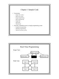
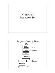
Microtime Computer Inc.2. Directories and FilesFigure-1 shows the architecture of <strong>ePBB</strong> and its relationship with hardware platform.Figure-1. <strong>ePBB</strong> Architecture2-1 ePPB <strong>Development</strong> <strong>Guide</strong>
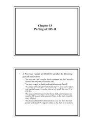
Microtime Computer Inc.Figure-2 shows the directory structure after <strong>ePBB</strong> being installed (cloned).Figure-2. <strong>ePBB</strong> Directory StructureAll files are placed under the <strong>ePBB</strong> directory. There are three major sub-directories.● Applications● Drivers● Libraries: Contains all the available project examples: Contains drivers for all devices: Contains packages from RTOS and MCU vendorsFollowing sections briefly describe the contents of all directories. For easy explanation, we make thefollowing assumption :● Target board : PTK-STM32F207 (Microtime product)● Compiler : EWARM (IAR Systems product)ePPB <strong>Development</strong> <strong>Guide</strong> 2-2
Microtime Computer Inc.2.1. Directory : <strong>ePBB</strong>\ApplicationsThis directory contains all the project examples of <strong>ePBB</strong>. The contained sub-directories are organizedin concept of :● Projects are grouped in board (MCU-System) basis :PTK-STM32F207, PTK-LPC1768, PTK-NUC140, ...● Each board may be targeted with different compilers :IAR-EWARM, KEIL-MDK-ARM, ...● Provides examples for RTOS or standalone applications :uCOS-II, FreeRTOS, UML_visualSTATE, standalone, ...● Keeping all the reusable codes / files in one place and do not have second copy of them foreasy maintenance.This directory contains two additional sub-directories :● \Projects● \Examples<strong>ePBB</strong>\Applications\Projects contains project files for a variety of boards and compilers. Below showsthe naming convention for the directory structure :For example :● <strong>ePBB</strong>\Applications\Projects\PTK-STM32F207\EWARM-V6\OS_None\led contains theIAR-EWARM V6.30 project of led non-OS example which can be executed inPTK-STM32F207 board.<strong>ePBB</strong>\Applications\Examples contains reusable source files for all examples. Below shows thenaming convention for the directory structure :For example :● <strong>ePBB</strong>\Applications\Examples\ OS_None \led contains the source files (\src) and includefiles (\inc) for led sample project.2-3 ePPB <strong>Development</strong> <strong>Guide</strong>
Microtime Computer Inc.2.2. Directory : <strong>ePBB</strong>\DriversThis directory contains the device drivers for application use. The contained sub-directories areorganized in concept of :● Drivers are grouped in components basis :LED, Button, Buzzer, Motor, ...● Some common access methods of microprocessor system are included also :I2C, UART, ...● Drivers are referenced via predefined APIs and they are platform (MCU) independent.● Some platform depended device drivers are grouped in a special directory (\Portings) and aremanaged in MCU or board basis.● The coding convention of drivers should be compiler independentUnder <strong>ePBB</strong>\Drivers, two additional sub-directories are included :● \Portings● \Sources<strong>ePBB</strong>\Drivers\Sources contains directories for placing the source files of device drivers. By providingAPIs for devices, it's more easily for programmers to handle devices without having too muchknowledge about it. Below shows the naming convention for the directory structure :For example :● <strong>ePBB</strong>\Drivers\Sources\led contains the driver of LED lamp and it is platform (MCU)independent.<strong>ePBB</strong>\Drivers\Portings contains the porting portions of drivers. This helps the source code of driver in<strong>ePBB</strong>\Drivers\Sources can be utilized by and targeted to more MCU. Below shows the namingconvention for the directory structure :For example :● <strong>ePBB</strong>\Driver\Portings\STM32F2xx\PTK-STM32F207 contains the PTK-STM32F207 portingfor all device drivers which included in <strong>ePBB</strong>\Driver\Sources if applied.ePPB <strong>Development</strong> <strong>Guide</strong> 2-4
Microtime Computer Inc.2.3. Directory : <strong>ePBB</strong>\LibrariesThis directory contains some useful packages such as drivers for managing MCU peripherals, headerfiles for MCU registers definition. Also the framework of some popular RTOSs are included forapplication need.The contained sub-directories are organized in concept of :● To get all the available firmware support from third parties such as :ST-Microelectronics, NXP, Nuvoton, ...● To get all the available framework support from third parties such as :Micrium, FreeRTOS.org, ...● To keep the original structure of the framework as possible.This directory contains further sub-directories :●●●●\Firmwares\Middlewares\OS_uCOS-II\OS_ uCOS-III<strong>ePBB</strong>\Libraries\Firmwares contains directories for firmware which provided by chip (MCU) vendors.Firmware, the foundation of embedded programming, is usually the basic building block of modernoperating systems such as uCOS-II and FreeRTOS. It provides a convenient and effective way forprogrammers to deal with MCU. Also the programmers do not need to study too much about the detailsof control procedures or registers definition. Below shows the naming convention for the directorystructure :For example :…..● <strong>ePBB</strong>\Libraries\Firmwares\ST\STM32F2xx\STM32F2xx_StdPeriph_Driver contains thefirmware of peripherals drivers for ST-Microelectronics STM32F2xx MCU series.● <strong>ePBB</strong>\Libraries\Firmwares\ST\STM32F2xx\CMSIS\CM3\DeviceSupport\ST\STM32F2xx\system_stm32f2xx.c is the CMSIS Cortex-M3 device peripheral access layer system sourcefile.● <strong>ePBB</strong>\Libraries\Firmwares\ST\STM32F2xx\CMSIS\CM3\DeviceSupport\ST\STM32F2xx\stm32f2xx.h contains all the peripheral register's definitions, bits definitions and memorymapping for STM32F2xx devices.2-5 ePPB <strong>Development</strong> <strong>Guide</strong>
Microtime Computer Inc.<strong>ePBB</strong>\Libraries\Middlewares contains some useful software packages which lies between theoperating system and applications. Such as, File system, TCP/IP, GUI and USB stack are mostcommonly used among them. Middleware is sometimes used in a similar sense to a software driver, anabstraction layer that hides detail about hardware devices or other software from an application.<strong>ePBB</strong>\Libraries\uCOS-II contains RTOS framework of Micrium's uCOS-II V2.9x Kernel. It is apriority-based pre-emptive real-time multitasking operating system kernel for microprocessors, writtenmainly in the C programming language. It is intended for use in embedded systems. It is a very smallreal-time kernel. The memory footprint is about 20KB for a fully functional kernel. Middleware likeuC/GUI, uC/TCP-IP, uC/USB and uC/FS are also integrated. (In our packages, none of Micrium'smiddleware is included.)Important :Under \<strong>ePBB</strong>\Libraries\uCOS-II, we keep the directory structure same as Micrium provided, but thatdoesn't mean we provide all the source code you need for application building. To evaluate all the uCOSexamples that <strong>ePBB</strong> provided, you still have to get the kernel source and fix-up/overwrite the <strong>ePBB</strong>package.Appendix-A figures out more details about that.Below shows the naming convention for the directory structure :…..2.4. Directory : <strong>ePBB</strong>\DocumentationsThis directory contains some of useful documentations for programming need.ePPB <strong>Development</strong> <strong>Guide</strong> 2-6
Microtime Computer Inc.3. Getting Started with <strong>ePBB</strong>In this chapter we see how easy it is to utilize all the building blocks in <strong>ePBB</strong> to build executable imagefor our target board.Application examples explained in this chapter are based on the following assumptions :● Using PTK-STM32F207 as hardware platform● Using IAR-EWARM for project management and image buildIt should be applied for adopting the same examples to other hardware platforms and compilers.Before building and testing any example project, make sure that all the following tasks areaccomplished :● Hardware platform, e.g. PTK-STM32F207, should be installed for code execution.● Debugger probe, e.q. J-Link Lite, should be installed for code loading and debugging.● Code generation tools, e.g. IAR EWARM-KS, should be installed for project building. IAREWARM-KS, the code size limited version of EWARM, should be suitable for most of theavailable examples in <strong>ePBB</strong>.● <strong>ePBB</strong> should be deployed (copied) to the working directory in your host computer.Note :For hardware platform installation, checking relative document for details. "Section :Hardware Installation" of "PTK-MCU-STM32F207 User’s <strong>Guide</strong>" describes details on platformhardware installation.Note :IAR EWARM-KS and <strong>ePBB</strong> are bundled with PTK product. For installation, one should checkthe "Software Installation" section of "PTK-MCU-XXX user guide" for details.3.1. Standalone Sample Projects3.1.1. Example_1 : LED BlinkingScenario :This project initializes and configures the GPIO ports of MCU for LEDs control. After being initialized,code then runs into an infinite loop and drives the LEDs in blinking state constantly.Project Browsing :<strong>ePBB</strong>\Applications\Projects\PTK-STM32F207\EWARM-V6\OS_None\base_led\demo.eww3-1 ePPB <strong>Development</strong> <strong>Guide</strong>
Microtime Computer Inc.Figure-3. LED project (Standalone)Code Listing :List-1. LED Project execution starts at main() (Standalone : main.c)List-1-(1) :Call this function to perform system initialization for PTK board, such as toggling systemreset signal to reset all the connected I/O devices.List-1-(2) :This statement configures MCU I/O pins which drive the LEDs as GPIO output function.List-1-(3) :Here we turn the LED off, the argument indicates which LED should be controlled.ePPB <strong>Development</strong> <strong>Guide</strong> 3-2
Microtime Computer Inc.List-1-(4) :The always true statement leads to the infinite loop operation. The following threestatements are involved in this never ending story.List-1-(5) :Here we toggle the LED from ON to OFF or vice versa, the argument indicates which LEDshould be controlled.List-1-(6) :This delay routine allow MCU to be "postponed" for a specified period. The argumentspecifies the delay time in unit of millisecond (1/1000 second).3.1.2. Example_2 : Button DetectingScenario :This project initializes and configures the GPIO ports of MCU for buttons sensing and LEDsilluminating. After being initialized, code then runs into an infinite loop and perform the followingtasks :● Detecting button state (Pressed or Released)● Controlling the LED accordinglyProject Browsing :<strong>ePBB</strong>\Applications\Projects\PTK-STM32F207\EWARM-V6\ OS_None \base_button\demo.ewwFigure-4. Button project (Standalone)3-3 ePPB <strong>Development</strong> <strong>Guide</strong>
Microtime Computer Inc.Code Listing :List-2. Button Project execution starts at main() (Standalone : main.c)List-2-(1) :Call this function to perform system initialization for PTK board, such as toggling systemreset signal to reset all the connected I/O devices.List-2-(2) :This statement configures MCU I/O pins which connect to the buttons as GPIO inputfunction.List-2-(3) :This statement configures MCU I/O pins which drive the LEDs as GPIO output function.List-2-(4) :Here we turn the LED off, the argument indicates which LED should be controlled.List-2-(5) :The always true statement leads to the infinite loop operation. The following statementsare involved in this never ending story.List-2-(6) :Call this function to get the state of button (Pressed or Released). Using the returned stateto compare with condition "KEY_PRESSED".List-2-(7) :If given condition is TRUE, i.e. the button is pressed, function module_led_on(LED0_IDX)will get executed. This leads to LED0 be turned ON.List-2-(8) :If given condition is not TRUE, i.e. the button is released, functionmodule_led_off(LED0_IDX) will get executed. This leads to LED0 be turned OFF.ePPB <strong>Development</strong> <strong>Guide</strong> 3-4
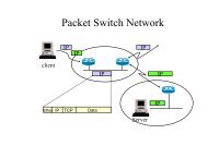
Microtime Computer Inc.3.1.3. Example_3 : Buzzer BeepingScenario :This project initializes and configures the GPIO ports of MCU which connects to the buzzer for tonegeneration. After I/O port being initialized, code then runs into an infinite loop and perform thefollowing tasks :● The buzzer start beeping for a specified period● The buzzer stop beeping for a specified periodProject Browsing :<strong>ePBB</strong>\Applications\Projects\PTK-STM32F207\EWARM-V6\ OS_None \base_buzzer\demo.ewwApplication groupStartup programmain() program<strong>ePBB</strong> LibrariesPTK Buzzerdevice driverPTK board levelInitial programMCU peripheralsdriverProject map fileProject image fileFigure-5. Buzzer project (Standalone)Code Listing :List-3. Buzzer Project execution starts at main() (Standalone : main.c)3-5 ePPB <strong>Development</strong> <strong>Guide</strong>
Microtime Computer Inc.List-3-(1) :Call this function to perform system initialization for PTK board, such as toggling systemreset signal to reset all the connected I/O devices.List-3-(2) :This statement configures MCU I/O pins which connect to the buzzer as GPIO outputfunction. The tone frequency of beep sound is also configured to default value of 500Hz.List-3-(3) :The always true statement leads to the infinite loop operation. The following statementsare involved in this never ending story.List-3-(4) :Call this function to turn buzzer on and start beeping at 500Hz tone frequency.List-3-(5) :This delay routine allow MCU to be "postponed" for a specified period. The argumentspecifies the delay time in unit of millisecond (1/1000 seconds).List-3-(6) :Call this function to turn buzzer off.3.1.4. Example_4 : InterruptScenario :This project demonstrates● How I/O pins can be configured as a trigger device for interrupt triggering.● How interrupt mechanism in core and peripheral module should be organized for properoperation.● How the service routine is linked, so MCU can jump to the right place for interrupt servicing.When project executing, press the button in target board, KEY0, and check if LED is toggledaccordingly.Note :The control process and code explanation shown in this section is specifically used forPTK-STM32F207 and may not be applied for other platforms.Project Browsing :<strong>ePBB</strong>\Applications\Projects\PTK-STM32F207\EWARM-V6\OS_None\base_button_irq\demo.ewwePPB <strong>Development</strong> <strong>Guide</strong> 3-6
Microtime Computer Inc.Figure-6. Interrupt project (Standalone)Code Listing :List-4. Trigger Interrupt via Button (Standalone : main.c)3-7 ePPB <strong>Development</strong> <strong>Guide</strong>
Microtime Computer Inc.List-4-(1) :Call this function to perform system initialization for PTK board, such as toggling systemreset signal to reset all the connected I/O devices.List-4-(2) :This statement configures MCU I/O pin which drive the LED as GPIO output function.List-4-(3) :Call this function to perform following tasks :● To configure MCU pin which senses the state of button as input function. (PA0 inthis case)● To connect button I/O as interrupt source of EXTI0 (External Interrupt Line 0)● To setup EXTI0 propertiesList-4-(4) :Since interrupt service routine is expected to accomplish all the work, we just call delayroutine and do nothing in the infinite loop.List-4-(5) :These statements configure PA0 as input pin for button sensing and interrupt triggering.List-4-(6) :This statement link PA0 to EXTI0 as interrupt source.List-4-(7) :These statements setup properties and enable interrupt for peripheral EXTI0 (in peripheralmodule).List-4-(8) :These statements setup properties and enable interrupt for channel EXTI0 of NVIC (incore module).List-4-(9) :Once EXTI0 interrupt is triggered, MCU jumps here for servicing interrupt EXTI0. Entry-23of vector table defines the entry point of EXTI0. Usually vector table is coded in assemblyform and should be treated as part of startup program. Checking file "startup_stm32f2xx.s"for details about that.List-4-(10) :To response the interrupt (Button Press) by toggling LED.List-4-(11) :To clear the EXTI0 pending bit and allow the next trigger of interrupt EXTI0.3.2. OS_uCOS-II Sample ProjectsImportant :Under \<strong>ePBB</strong>\Libraries\uCOS-II, we keep the directory structure same as Micrium provided, but thatdoesn't mean we provide all the source code you need for application building. To evaluate all the uCOSexamples that <strong>ePBB</strong> provided, you still have to get the kernel source and fix-up/overwrite the <strong>ePBB</strong>package. Appendix-A figures out more details about that.ePPB <strong>Development</strong> <strong>Guide</strong> 3-8
Microtime Computer Inc.3.2.1. Example_1 : Single-Task (LED Blinking)Scenario :This project demonstrates● What does uCOS-II framework contain● How to initialize uCOS-II framework for services● How to create a uCOS-II task for application● What is a typical uCOS-II task looks likeWhen project executing, LED in target board should be set in blink state.Project Browsing :<strong>ePBB</strong>\Applications\Projects\PTK-STM32F207\EWARM-V6\OS_uCOS-II\base_single_task\demo.ewwFigure-7. Single-Task project (OS_uCOS-II)Code Listing :3-9 ePPB <strong>Development</strong> <strong>Guide</strong>
Microtime Computer Inc.List-5. Single-Task project execution starts at main() (OS_uCOS-II : app.c)List-5-(1) :Start main() by calling BSP_IntDisAll() that disable all interrupts. On most processors,though interrupt are disabled at startup time, it's more safer to turn off all peripheralinterrupts at this moment.List-5-(2) :Call OSInit() to initialize uCOS-II framework, such as :● Internal variables and data structures● Creates internal use tasks (idle, tick, timer, ...)It's important to note that OSInit() must be called before any other uCOS-II functions.List-5-(3) :OSTaskCreateExt() creates a task to be managed by uC/OS-II. Tasks can be createdeither prior to the start of multitasking or by a running task.List-5-(4) :It's a pointer which points to the task’s codeList-5-(5) :It's a pointer which points to the top of task’s stackList-5-(6) :It's the task priority. A unique priority number must be assigned to each task: the lower thenumber, the higher the priority (i.e., the importance) of the task.List-5-(7) :It's task's ID. You should set id to the same value as the task’s priority.List-5-(8) :It's a pointer which points to the bottom of task’s stack.ePPB <strong>Development</strong> <strong>Guide</strong> 3-10
Microtime Computer Inc.List-5-(9) :It specifies the size of the task’s stack in number of elements. The size of element could bebyte(8-bit), word(16-bit) or long-word(32-bit).List-5-(10) :It contains task-specific options such as :● OS_TASK_OPT_STK_CHK● OS_TASK_OPT_STK_CLR● ...List-5-(11) :OSTaskNameSet() allows you to assign a name to a task. This function is typically used bydebugger to associate a task name to task. Here we assign "Start Task" to taskApp_TaskStart().List-5-(12) :The final step in main() is to call OSStart(), which starts the multitasking process. OSStart()is never returned after calling.List-6. The first application task : App_TaskStart() (OS_uCOS-II : app.c)List-6-(1) :Task looks like any other C function, the argument p_arg is passed to App_TaskStart() byOSTaskCreateExt().List-6-(2) :It's a BSP function that is responsible for initializing the hardware on target board. It'slocated in file bsp.cList-6-(3) :CPU_Init() initialize the uC/CPU services.List-6-(4) :BSP_CPU_ClkFreq() determines the system tick reference frequency of the board.3-11 ePPB <strong>Development</strong> <strong>Guide</strong>
Microtime Computer Inc.Typically it's refer to the core clock frequency. The number of system tick per OS tick iscalculated by cnt = BSP_CPU_ClkFreq() / OS_TICKS_PER_SEC e.g. setOS_TICKS_PER_SEC to 1000 means the resolution of OS tick is 1/1000 seconds. For asystem like PTK-STM32F207, with MCU running at 120MHz core frequency the result ofcnt should be 120,000.List-6-(5) :Finally, pass the calculated cnt value to OS_CPU_SysTickInit() for OS tick setup. The OSsystem tick interrupt should be triggered once every 1/1000 seconds.List-6-(6) :OSStatInit() determines the maximum value that a 32-bit counter can reach when no othertask is executing.List-6-(7) :A typical RTOS task is implemented as an infinite loop. This is the first statement in theloop.BSP_LED_Toggle() is a BSP function which can be used for LED toggling.List-6-(8) :OSTimeDly() suspends task execution for a specified period. It's not only used for timekilling but releasing the CPU time for other tasks that are ready for execution.3.2.2. Example_2 : Multi-Task (LEDs Dancing)Scenario :According to , we've learned what is uCOS-II looks like and how to create task for applicationneed. In this section we'll try more about creating more task for our project and check if two taskswork as expected.When project executing, LEDs in target board should be set in blink state and the blinking rate ofeach LED should be different. You may found that the dancers, LED1 and LED2,are not evensynchronized in pace. Do you know why ?Project Browsing :<strong>ePBB</strong>\Applications\Projects\PTK-STM32F207\EWARM-V6\OS_uCOS-II\base_multi_task\demo.ewwePPB <strong>Development</strong> <strong>Guide</strong> 3-12
Microtime Computer Inc.Figure-8. Multi-Task project (OS_uCOS-II)Code Listing :The code of function main() is the same as main() function of "OS_uCOS-II Single-Task project"which is described in previous section. You may check List-6 and corresponding explanations forreference.3-13 ePPB <strong>Development</strong> <strong>Guide</strong>
Microtime Computer Inc.List-7. Creating TASK by application task (OS_uCOS-II : app.c)List-7-(1) :In App_TaskStart(), the first user's task, call App_TaskCreate() to create another task forapplication. Details of App_TaskCreate() will be explained later.List-7-(2) :After board being initialized, task "Start Task" runs into infinite loop and start toggling LED1once every 1/10 seconds.List-7-(3) :This argument indicates that App_TaskSecond() is the entry point of the task that will becreated.List-7-(4) :The second task, App_TaskSecond(), is named as "Second Task", and is used fordebugging purpose.List-7-(5) :It's the body of the second task.List-7-(6) :After task being activated, it runs into infinite loop and start toggling LED2 once every 0.5seconds.ePPB <strong>Development</strong> <strong>Guide</strong> 3-14
Microtime Computer Inc.3.2.3. Example_3 : InterruptScenario :This project demonstrates● How I/O pins can be configured as a trigger device for interrupt triggering.● How interrupt mechanism in uCOS-II should be organized for proper operation.When project executing, press the button in target board, KEY0, and check if LED is toggledaccordingly.Note :The control process and code explanation shown in this section is specifically used forPTK-STM32F207 and may not be applied for other platforms.Project Browsing :<strong>ePBB</strong>\Applications\Projects\PTK-STM32F207\EWARM-V6\OS_uCOS-II\base_button_irq\demo.ewwApplication groupVector tableStartup programmain() programUCOS-II boardsupport packageBSP :board device driverBSP :interrupt handling codeBSP :MCU peripheralclock control code<strong>ePBB</strong> LibrariesPTK board levelInitial programPTK LED devicedriverMCU peripheralsdriverUCOS-II :RTOS frameworkProject map fileProject image fileFigure-9. Interrupt project (OS_uCOS-II)3-15 ePPB <strong>Development</strong> <strong>Guide</strong>
Microtime Computer Inc.Code Listing :List-8. Trigger Interrupt via Button (uCOS-II : app.c)List-8-(1) :Checking for details about the explanation of main().List-8-(2) :Call EXTILine0_Config() to perform following tasks :● To configure MCU pin which senses the state of button as input function. (PA0 inthis case)ePPB <strong>Development</strong> <strong>Guide</strong> 3-16
Microtime Computer Inc.● To connect button I/O as interrupt source of EXTI0 (External Interrupt Line 0)● EXTI0 properties setupList-8-(3) :App_TaskStart() keeps toggling LED0 in the infinite loopList-8-(4) :These statements configure PA0 as input I/O pin for button sensing and interrupttriggering.List-8-(5) :This statement link PA0 to EXTI0 as interrupt source.List-3-(6) :These statements setup properties and enable interrupt for peripheral EXTI0 (in peripheralmodule).List-8-(7) :BSP_IntVectSet() installs EXTI0_IRQHandler, function pointer which points to interruptservice routine, to data structure BSP_IntVectTbl[]. List-9 shows details about the usage.List-8-(8) :It's the entry of EXTI0 interrupt service routine and perform the following tasks :● Toggling LED1● To clear the EXTI0 pending bit and allow the next trigger of interrupt EXTI0.List-9. Interrupt Routing (uCOS-II)3-17 ePPB <strong>Development</strong> <strong>Guide</strong>
Microtime Computer Inc.List-9-(1) :The application setup interrupt vector for EXTI0 by calling BSP_IntVectSet() . The interruptID and function pointer are passed as arguments.List-9-(2) :BSP_IntVectSet() maintains a data structure, BSP_IntVectTbl[ ], to keep function pointerswhich point to corresponding interrupt service routines for system. In our case, functionpointer EXTI0_IRQHandler is placed at entry BSP_INT_ID_EXTI0 of BSP_IntVectTbl[].List-9-(3) :After button being pressed, interrupt EXTI0 is triggered and interrupt table is searched forMCU execution jump.List-9-(4) :MCU decides to jump to BSP_IntHandlerEXTI0() according the result of table searching.List-9-(5) :BSP_IntHandler() handles all of the interrupt requests by checking BSP_IntVectTbl[] anddispatching them accordingly. Following descriptions depict more details about that.List-9-(6) :Use int_id as index to get function pinter from BSP_IntVectTbl[]List-9-(7) :EXTI0_IRQHandler is chosen and assigned to isr.List-9-(8) :EXTI0_IRQHandler() is finally executed.3.2.4. Example_4 : Console Application : Hello World !!!Scenario :This project demonstrates how to create console, RS-232 communication, for PC host to link with.Not only for application use, dump messages via console for debugging and analysis is also helpful.There are more requirements in system installation for this project :● Terminal Emulation software should be installed in your host computer, use Hyper-Terminalin our case.● Setup communication properties for terminal emulator : 115200, N, 8, 1● Use standard RS-232 cable to link target board with PC host.Below shows the system configuration needed for console projectePPB <strong>Development</strong> <strong>Guide</strong> 3-18
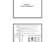
Cortex-M3Debug + ETMMicrotime Computer Inc.PC-HOST :1. Debugger2. Terminal110V12V DCAdaptoriMacDC-12VCN1DCDCCN15RJ-45D12USB CableRS-232 CableCN2CN12PWR_DBGCN5CN6RF-EXT-1PTK-BASECN13PHYCN16PER-EXTCN19BOOT0CN7CN8J-Link Lite ARM20-Pin JTAG CableCN11BUZZERSU1PTK-MCU-STM32F207JP1MEMS-2U7CN18CN9CN10MEMS-1RESETU5KEY3KEY2KEY1KEY0HEX1VR1D11CN4TemperatureU3JP1DIP-SWLightLED3LED2LED1LED0POWERFigure-10. System configuration for console projectBelow shows steps needed for system test :● Invoke terminal emulation program and connect to the COM port which linked to our targetsystem.● Load the project and run the target board, or reset target board if it is already in runningstate.● Message "Hello World !!!" shows on terminal.● Target board responses any key stroke in PC terminal with the same character it received.Figure-11. Snapshot of Hello World !!!Project Browsing :<strong>ePBB</strong>\Applications\Projects\PTK-STM32F207\EWARM-V6\OS_uCOS-II\base_uart\demo.eww3-19 ePPB <strong>Development</strong> <strong>Guide</strong>
Microtime Computer Inc.Application groupVector tableStartup programmain() programUCOS-II boardsupport packageBSP :board device driverBSP :interrupt handling codeBSP :MCU peripheralclock control codeBSP :UART driver<strong>ePBB</strong> LibrariesPTK board levelInitial programPTK LEDdevice driverPTK UARTdevice driverMCU peripheralsdriversUCOS-II :RTOS frameworkProject map fileProject image fileFigure-12. Console project (OS_uCOS-II)Code Listing :The following code sections perform the same functionality as described in and .Checking List-5~List-7 and corresponding explanations for details please.● main()● App_TaskStart()● App_TaskCreate()Below briefly explains how UART task works.ePPB <strong>Development</strong> <strong>Guide</strong> 3-20
Microtime Computer Inc.List-10. The UART process task (OS_uCOS-II : app.c)List-10-(1) :It's a uCOS-II BSP function call which performs the following works :● To initialize MCU I/O and UART peripheral by calling functions of UART devicedriver.● Configure interrupt for UART TX and RX service routines.● Create semaphores for managing common resources such as UART device, UARTtransmission and UART receiving.List-10-(2) :This function performs formatted print to dump string "Hello World !!!" to the specifiedUART device (console APP_UARTA).List-10-(3) :Call this function to get (read) a byte of data from specified UART device (consoleAPP_UARTA).List-10-(4) :Call this function to put (write) a byte of data to specified UART device (consoleAPP_UARTA).3-21 ePPB <strong>Development</strong> <strong>Guide</strong>
Microtime Computer Inc.Appendix-A About Micrium kernel sourceSource code for μC/OS-II(III) can be downloaded from the Micriμm website, the website of authorizeddistributors or as part of evaluation kits from semiconductor manufacturers.Colleges and Universities can use μC/OS-II(III) for free as long as it’s for educational purposes orpeaceful research.A.1. Licensing PolicyuC/OS-II(III) are provided in source form for FREE short-term evaluation, for educational use or forpeaceful research. If you plan or intend to use uC/OS-II(III) in a commercial application/product then,you need to contact Micrium to properly license uC/OS-II(III) for its use in your application/product.Micrium provides ALL the source code for your convenience and to help you experience uC/OS-II(III).The fact that the source is provided does NOT mean that you can use it commercially without paying alicensing fee. It is necessary to purchase the license when the decision to use μC/OS-II(III) in a designis made, not when the design is ready to go to production.If you are unsure about whether you need to obtain a license for your application, please contactMicrotime or Micriμm and discuss your use with a sales representative.A.2. Download Micrium kernel source codeAll the information shown in this section was tailored from Micrium's website while writting thisdocument. So the real contents you browse may changed if there is change made by Micrium.To get the kernel source, you should visit Micrium's download page and select "Micrium Source code".Figure-A1. Micrium's download pageA-1 ePPB <strong>Development</strong> <strong>Guide</strong>
Microtime Computer Inc.Now, we are in a new page called "Download μC/OS Source Code" as shown below. To select"Download Micrium uCOS-II" or "Download Micrium uCOS-III" in your need. Here we select "DownloadMicrium uCOS-II" for evaluation.Figure-A2. Download μC/OS Source CodeSince registration is required to download these files. If you do not already have an account atmicrium.com, you will be prompted to create one. Once you get the free account from Micrium, youmay get into the download page for source code download.Figure-A3. Login your accountePPB <strong>Development</strong> <strong>Guide</strong> A-2
Microtime Computer Inc.Figure-A4. Source Code DownloadA.3. Fix-Up <strong>ePBB</strong> with the loaded kernel sourceThis section describes how to setup the kernel source code you got from Micrium. Let's say, you've gotbelow two packages from Micrium :1. The uC-OS-II kernel source : Micrium-uCOS-II-V290.zip2. The uC-OS-III kernel source : KRN-K3XX-000000.zipUnzip these two files and get the file structures as shown below.Figure-A5. File content of uCOS-II and uCOS-III kernelFor uCOS-II kernel code fix-up, you should copy folder and all of its sub-folders to thefollowing <strong>ePBB</strong> path<strong>ePBB</strong>\Libraries\OS_uCOS-II\Micrium-V29xand following path for uCOS-III users<strong>ePBB</strong>\Libraries\OS_uCOS-II\Micrium-V30xA-3 ePPB <strong>Development</strong> <strong>Guide</strong>