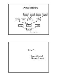
PTK-STM32F207
PTK-STM32F207
PTK-STM32F207
- No tags were found...

You also want an ePaper? Increase the reach of your titles
YUMPU automatically turns print PDFs into web optimized ePapers that Google loves.
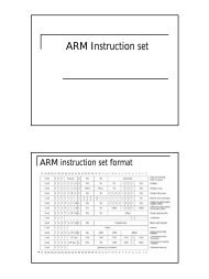
<strong>PTK</strong>-<strong>STM32F207</strong>an ARM Cortex-M3 core
<strong>PTK</strong>-MCU-<strong>STM32F207</strong> Block Diagram• <strong>PTK</strong>-MCU : CPU modules• <strong>PTK</strong>-MEMS : Sensor modules• <strong>PTK</strong>-RF : RF modules• <strong>PTK</strong>-PER : Peripheral modules
Routing Diagram : <strong>PTK</strong>-MCU-<strong>STM32F207</strong> +<strong>PTK</strong>-BASE + <strong>PTK</strong>-PER-TFT<strong>PTK</strong>-MCU-<strong>STM32F207</strong><strong>PTK</strong>-Base<strong>PTK</strong>-PER-TFT
<strong>PTK</strong>-Base Hardware
<strong>PTK</strong>-BASE I/O and peripherals• Communication :– USB, Ethernet, RS-232, RS-485 and CAN• GPIO :– LEDs, Buttons, DIP-Switch, 7-Segment LED and Buzzer• Sensors :– Temperature, Light, Potentiometer and Infrared TX/RX• Storage :– SD-Socket and Serial EEPROM
<strong>PTK</strong>-PER-TFT
<strong>PTK</strong>-PER-TFT Block Diagram
<strong>PTK</strong>-PER-TFT• TFT LCD module : 2.8", 240 RGB X 320 , 65536color• Touch panel support• 16-Bit stereo audio codec with Class-D amplifier• Microphone and Speaker on board for music playingand recording• Mini vibration motor on board for non-audibleindicators• Two joysticks with 2D analog outputs and one digitalout for control and gaming applications• Provides extension slots for MEMS and RF modules
Hardware connectivity
J-Link Driver• J-Link driver is in the following direction– C:\Program Files\IAR Systems\EmbeddedWorkbench 6.4\arm\drivers\Jlink\x86
ePBB ,embedded Programmer's Building Blocks
ePBB, "embedded Programmer's Building Blocks"
Getting Start: Build and Load ApplicationToggling the LED in a constant rate• 1. Start the IAR Embedded Workbench for ARM• 2. open the following workspace (project)– C:\Microtime\<strong>PTK</strong>\ePBB\Applications\Projects\<strong>PTK</strong>-<strong>STM32F207</strong>\EWARM-V6\OS_None\base_led\demo.eww
Workspace and project "demo"opened
Click on "Download and Debug"• The IAR-EW will compile and link the demo codeand load (burn) the image onto the on-chip Flash of<strong>STM32F207</strong>
Run the project• the code will start executing and stop at main()in 'main.c',
Dancing LEDs
LCD test• Open LCD test project :– C:\Microtime\<strong>PTK</strong>\ePBB\Applications\Projects\<strong>PTK</strong>-<strong>STM32F207</strong>\EWARM-V6\OS_None\per_lcd\demo.eww– Prepare SD card• Format as FAT32 format.• Insert the SD card into your PC host and copy the following file toSD card.ePBB\Applications\Examples\OS_None\per_lcd\inc\ballon.bmp• Remove SD card from PC host and insert it to SD slot on <strong>PTK</strong>-BASE– Compile demo.eww, download to <strong>PTK</strong> and run