Hardware Interface Description - Standard ICs
Hardware Interface Description - Standard ICs
Hardware Interface Description - Standard ICs

Create successful ePaper yourself
Turn your PDF publications into a flip-book with our unique Google optimized e-Paper software.
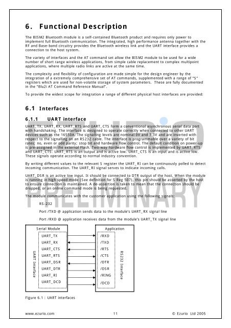
6. Functional <strong>Description</strong>The BISM2 Bluetooth module is a self-contained Bluetooth product and requires only power toimplement full Bluetooth communication. The integrated, high performance antenna together with theRF and Base-band circuitry provides the Bluetooth wireless link and the UART interface provides aconnection to the host system.The variety of interfaces and the AT command set allow the BISM2 module to be used for a widenumber of short range wireless applications, from simple cable replacement to complex multipointapplications, where multiple radio links are active at the same time.The complexity and flexibility of configuration are made simple for the design engineer by theintegration of a extremely comprehensive set of AT commands, supplemented with a range of “S”registers which are used for non-volatile storage of system parameters. These are fully documentedin the “Blu2i AT Command Reference Manual”.To provide the widest scope for integration a range of different physical host interfaces are provided:6.1 <strong>Interface</strong>s6.1.1 UART interfaceUART_TX, UART_RX, UART_RTS and UART_CTS form a conventional asynchronous serial data portwith handshaking. The interface is designed to operate correctly when connected to other UARTdevices such as the 16550A. The signalling levels are nominal 0V and 3.3V and are inverted withrespect to the signalling on an RS232 cable. The interface is programmable over a variety of bitrates; no, even or odd parity; stop bit and hardware flow control. The default condition on power-upis pre-assigned in the external Flash. Two-way hardware flow control is implemented by UART_RTSand UART_CTS. UART_RTS is an output and is active low. UART_CTS is an input and is active low.These signals operate according to normal industry convention.By writing different values to the relevant S register the UART_RI can be continuously polled to detectincoming communication. The UART_RI signal serves to indicate incoming calls.UART_DSR is an active low input. It should be connected to DTR output of the host. When the moduleis running in high speed mode (See definition for S Reg 507), this pin should be asserted by the hostto ensure connection is maintained. A de-assertion is taken to mean that the connection should bedropped, or an online command mode is being requested.The module communicates with the customer application using the following signals:RS-232Port /TXD @ application sends data to the module’s UART_RX signal linePort /RXD @ application receives data from the module’s UART_TX signal lineSerial ModuleApplicationUART_TX/RXDUART_RX/TXDUART_CTS/RTSUART <strong>Interface</strong>UART_RTSUART_DSRUART_DTRUART_RIUART_DCD/CTS/DTR/DSR/RING/DCDRS232 <strong>Interface</strong>Figure 6.1 : UART interfaceswww.ezurio.com 11© Ezurio Ltd 2005