Hardware Interface Description - Standard ICs
Hardware Interface Description - Standard ICs
Hardware Interface Description - Standard ICs
You also want an ePaper? Increase the reach of your titles
YUMPU automatically turns print PDFs into web optimized ePapers that Google loves.
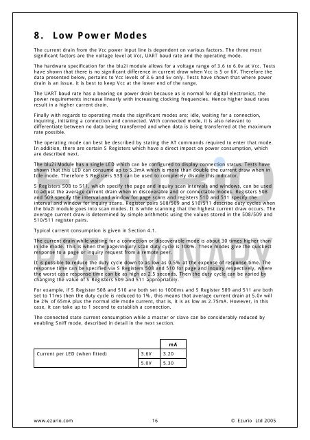
8. Low Power ModesThe current drain from the Vcc power input line is dependent on various factors. The three mostsignificant factors are the voltage level at Vcc, UART baud rate and the operating mode.The hardware specification for the blu2i module allows for a voltage range of 3.6 to 6.0v at Vcc. Testshave shown that there is no significant difference in current draw when Vcc is 5 or 6V. Therefore thedata presented below, pertains to Vcc levels of 3.6 and 5v only. Tests have shown that where powerdrain is an issue, it is best to keep Vcc at the lower end of the range.The UART baud rate has a bearing on power drain because as is normal for digital electronics, thepower requirements increase linearly with increasing clocking frequencies. Hence higher baud ratesresult in a higher current drain.Finally with regards to operating mode the significant modes are; idle, waiting for a connection,inquiring, initiating a connection and connected. With connected mode, it is also relevant todifferentiate between no data being transferred and when data is being transferred at the maximumrate possible.The operating mode can best be described by stating the AT commands required to enter that mode.In addition, there are certain S Registers which have a direct impact on power consumption, whichare described next.The blu2i Module has a single LED which can be configured to display connection status. Tests haveshown that this LED can consume up to 5.3mA which is more than double the current draw when inIdle mode. Therefore S Registers 533 can be used to completely disable this indicator.S Registers 508 to 511, which specify the page and inquiry scan intervals and windows, can be usedto adjust the average current drain when in discoverable and or connectable modes. Registers 508and 509 specify the interval and window for page scans and registers 510 and 511 specify theinterval and window for inquiry scans. Register pairs 508/509 and 510/511 describe duty cycles whenthe blu2i module goes into scan modes. It is while scanning that the highest current draw occurs. Theaverage current draw is determined by simple arithmetic using the values stored in the 508/509 and510/511 register pairs.Typical current consumption is given in Section 4.1.The current drain while waiting for a connection or discoverable mode is about 30 times higher thanin idle mode. This is when the page/inquiry scan duty cycle is 100%. These modes give the quickestresponse to a page or inquiry request from a remote peer.It is possible to reduce the duty cycle down to as low as 0.5% at the expense of response time. Theresponse time can be specified via S Registers 508 and 510 for page and inquiry respectively, wherethe worst case response time can be as high as 2.5 seconds. Then the duty cycle can be varied bychanging the value of S Registers 509 and 511 appropriately.For example, if S Register 508 and 510 are both set to 1000ms and S Register 509 and 511 are bothset to 11ms then the duty cycle is reduced to 1%, this means that average current drain at 5.0v willbe 2% of 65mA plus the normal idle mode current, that is, it is as low as 2.75mA. However, in thiscase, it can take up to 1 second to establish a connection.The connected state current consumption while a master or slave can be considerably reduced byenabling Sniff mode, described in detail in the next section.mACurrent per LED (when fitted)3.6V 3.205.0V 5.30www.ezurio.com 16© Ezurio Ltd 2005


