Hardware Interface Description - Standard ICs
Hardware Interface Description - Standard ICs
Hardware Interface Description - Standard ICs

You also want an ePaper? Increase the reach of your titles
YUMPU automatically turns print PDFs into web optimized ePapers that Google loves.
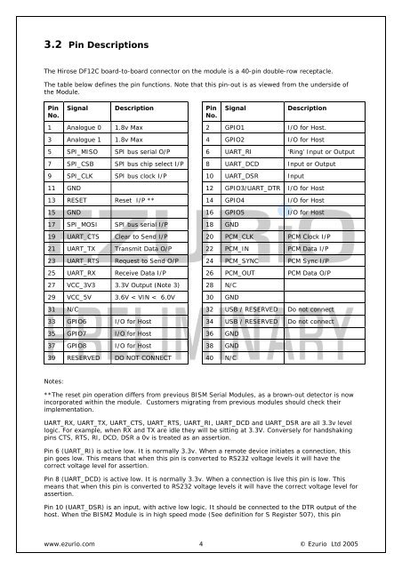
3.2 Pin <strong>Description</strong>sThe Hirose DF12C board-to-board connector on the module is a 40-pin double-row receptacle.The table below defines the pin functions. Note that this pin-out is as viewed from the underside ofthe Module.PinNo.Signal <strong>Description</strong> PinNo.Signal<strong>Description</strong>1 Analogue 0 1.8v Max 2 GPIO1 I/O for Host.3 Analogue 1 1.8v Max 4 GPIO2 I/O for Host5 SPI_MISO SPI bus serial O/P 6 UART_RI ‘Ring’ Input or Output7 SPI_CSB SPI bus chip select I/P 8 UART_DCD Input or Output9 SPI_CLK SPI bus clock I/P 10 UART_DSR Input11 GND 12 GPIO3/UART_DTR I/O for Host13 RESET Reset I/P ** 14 GPIO4 I/O for Host15 GND 16 GPIO5 I/O for Host17 SPI_MOSI SPI bus serial I/P 18 GND19 UART_CTS Clear to Send I/P 20 PCM_CLK PCM Clock I/P21 UART_TX Transmit Data O/P 22 PCM_IN PCM Data I/P23 UART_RTS Request to Send O/P 24 PCM_SYNC PCM Sync I/P25 UART_RX Receive Data I/P 26 PCM_OUT PCM Data O/P27 VCC_3V3 3.3V Output (Note 3) 28 N/C29 VCC_5V 3.6V < VIN < 6.0V 30 GND31 N/C 32 USB / RESERVED Do not connect33 GPIO6 I/O for Host 34 USB / RESERVED Do not connect35 GPIO7 I/O for Host 36 GND37 GPIO8 I/O for Host 38 GND39 RESERVED DO NOT CONNECT 40 N/CNotes:**The reset pin operation differs from previous BISM Serial Modules, as a brown-out detector is nowincorporated within the module. Customers migrating from previous modules should check theirimplementation.UART_RX, UART_TX, UART_CTS, UART_RTS, UART_RI, UART_DCD and UART_DSR are all 3.3v levellogic. For example, when RX and TX are idle they will be sitting at 3.3V. Conversely for handshakingpins CTS, RTS, RI, DCD, DSR a 0v is treated as an assertion.Pin 6 (UART_RI) is active low. It is normally 3.3v. When a remote device initiates a connection, thispin goes low. This means that when this pin is converted to RS232 voltage levels it will have thecorrect voltage level for assertion.Pin 8 (UART_DCD) is active low. It is normally 3.3v. When a connection is live this pin is low. Thismeans that when this pin is converted to RS232 voltage levels it will have the correct voltage level forassertion.Pin 10 (UART_DSR) is an input, with active low logic. It should be connected to the DTR output of thehost. When the BISM2 Module is in high speed mode (See definition for S Register 507), this pinwww.ezurio.com 4© Ezurio Ltd 2005