OAKTON Con 400-410/TDS 400 man - Oakton Instruments
OAKTON Con 400-410/TDS 400 man - Oakton Instruments
OAKTON Con 400-410/TDS 400 man - Oakton Instruments

You also want an ePaper? Increase the reach of your titles
YUMPU automatically turns print PDFs into web optimized ePapers that Google loves.
Table of <strong>Con</strong>tents1. Introduction............................................................................................42. Display and keypad functions .............................................................5-62.1 Display ...................................................................................................................................52.2 Keypad ...................................................................................................................................63. Preparation..........................................................................................7-93.1 Inserting the batteries ..........................................................................................................73.2 Probe information ................................................................................................................83.3 <strong>Con</strong>necting the probe to the meter....................................................................................94. Calibration .......................................................................................10-164.1 Important information on meter calibration .................................................................104.2 Preparing the meter for calibration .................................................................................114.3 <strong>Con</strong>ductivity calibration..............................................................................................12-134.4 <strong>TDS</strong> calibration..............................................................................................................14-154.4.1 Calibrating for <strong>TDS</strong> directly ....................................................................................144.4.2 Calibration with conductivity standard and <strong>TDS</strong> factor ....................................154.5 Temperature calibration...................................................................................................165. Measurement ...................................................................................17-225.1 Automatic Temperature Compensation .........................................................................175.2 Manual Temperature Compensation.........................................................................18-195.3 Taking Measurements .......................................................................................................205.4 Using <strong>man</strong>ual ranging function.......................................................................................215.5 Hold function......................................................................................................................226. Memory and data input functions ..................................................23-246.1 Memory Input.....................................................................................................................236.2 Memory Recall....................................................................................................................247.6 Program 5.0: Temperature ...........................................................................................35-36P5.1 Adjusting the temperature coefficient ....................................................................35P5.2 Adjusting the normalization temperature .............................................................367.7 Program 6.0: Selecting the cell constant..........................................................................377.8 Program 7.0: Setting the real-time clock....................................................................38-397.9 Program 8.0: Resetting to factory defaults .....................................................................408. Probe care and maintenance................................................................419. Troubleshooting....................................................................................4210. Error Messages....................................................................................4311. Specifications ......................................................................................4412. Accessories .....................................................................................45-4613. Addendum 1: Calibration tips ............................................................4714. Addendum 2: <strong>Con</strong>ductivity to <strong>TDS</strong> conversion factors ......................4815: Addendum 3: Calculating <strong>TDS</strong> <strong>Con</strong>version factors ............................4916. Addendum 4: Calculating temperature coefficients..........................5017. Addendum 5: Meter factory default settings ....................................5118. Warranty .............................................................................................5219. Return of Items...................................................................................527. SETUP functions ...............................................................................25-407.1 Set Up mode overview.................................................................................................26-277.2 Program 1.0: Memory clear...............................................................................................287.3 Program 2.0: Viewing calibration data............................................................................297.4 Program 3.0: Viewing probe data ....................................................................................307.5 Program 4.0: Unit configuration.................................................................................31-34P4.1: READY indicator and auto endpoint function.....................................................31P4.2: Selecting °C or °F ......................................................................................................32P4.3 Selecting Automatic or Manual Temperature Compensation.............................33P4.4 Setting the <strong>TDS</strong> factor (<strong>TDS</strong> <strong>400</strong> and CON <strong>410</strong> meters only)..............................3423
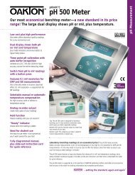
1. IntroductionThank you for selecting an <strong>OAKTON</strong> waterproof portable meter. This meter is amicroprocessor-based instrument that is completely waterproof—and it floats! Yourmeter features a built-in real time clock, expanded memory, and <strong>man</strong>y other userfriendlyfeatures, all of which are accessible through the membrane keypad.You have one of three models:• CON <strong>400</strong> meter: reads conductivity and temperature• <strong>TDS</strong> <strong>400</strong> meter: reads <strong>TDS</strong> and temperature• CON <strong>410</strong> meter: reads conductivity, <strong>TDS</strong> and temperatureYour meter includes a model WD-35608-50 Ultem/Stainless Steel cell (cell constantK = 1.0) and batteries.Please read this <strong>man</strong>ual thoroughly before operating your meter.READYMEASWATERPROOFµS2. Display and Keypad Functions2.1DisplayThe LCD has a primary and secondary display.• The primary display shows the measured conductivity or <strong>TDS</strong> reading.• The secondary display shows the temperature of the reading.The display also shows error messages, keypad functions and program functions.20.19.18.17.16.1.SETUPREADYHOLDONOFFK=2.MEAS3.CALMEMPrimary displaymSµSpptppmMEMERR C FAM PM4.ATC5.6.7.9.8.CATC15. 14.13. 12.11.Secondary display10.ONOFFHOLDCALMEASMI▲MRMODEENTERRANGE▼SETUP1. SETup mode indicator2. MEASurement modeindicator3. CALibration indicator4. MEMory recall modeindicator5. millisiemens indicator(CON <strong>400</strong> and CON <strong>410</strong>meters only)6. microsiemens indicator(OCN <strong>400</strong> and CON <strong>410</strong>meters only)7. parts per thousandindicator (<strong>TDS</strong> <strong>400</strong> andCON <strong>410</strong> meters only)8. parts per millionindicator (<strong>TDS</strong> <strong>400</strong> andCON <strong>410</strong> meters only)9. Temperature indicator10. AutomaticTemperatureCompensationindicator11. Clock indicator12. ERRor indicator13. MEMory locationindicator14. Low battery indicator15. Probe indicator16. Calibration solutionindicator16. Function ON/OFFindicator17. Cell constantindicator18. On/off indicator19. HOLD indicator20. READY indicator45
2.2KeypadThe large membrane keypad makes the instrument easy to use. Each button, whenpressed, has a corresponding graphic indicator on the LCD.ON/OFF ................Powers and shuts off the meter.HOLD ..................Freezes the measured reading. To activate, press HOLD while inmeasurement mode. To release, press HOLD again.MODE ..................Press to select the measurement parameter.CON <strong>400</strong> meter: Toggles between conductivity and time<strong>TDS</strong> <strong>400</strong> meter: Toggles between <strong>TDS</strong> and timeCON <strong>410</strong> meter: Toggles between conductivity, <strong>TDS</strong> and timeCAL/MEAS ..........Toggles user between Calibration and Measurement mode.NOTE: Temperature calibration is available from conductivitycalibration mode; see page 16 for directions.ENTER/RANGE..ENTER function: Press to confirm values in Calibration modeand to confirm selections in Setup mode.RANGE function: Press to enter <strong>man</strong>ual ranging function.The MEAS indicator blinks while in <strong>man</strong>ual ranging function...............Calibration mode: ▲ /▼ scrolls through calibration values.▲ ▼Setup mode: ▲ /▼ scrolls through subgroups and program options.................................MI/MR MRwork in the measurement mode.MI (memory input) stores the measured value into memory.MR (memory recall) recalls the sets of values stored in the memory.SET UP..................Press to enter SETUP mode. SETUP mode lets you customizemeter preferences, view calibration and probe offset data, andselect cell constant.3. Preparation3.1Inserting the BatteriesFour AAA batteries are included with your meter.1. Use a Phillips screwdriver to remove the two screws holding the battery cover.See figure below.2. Lift off battery cover to expose batteries.3. Insert batteries. Follow the diagram inside the cover for correct polarity.4. Replace the battery cover into its original position. Screw cover back into place.Remove thesetwo screws toaccess batterycompartmentONOFFHOLDMODEBatterycompartmentCALMEASENTERRANGEMI▲MR▼SETUP67
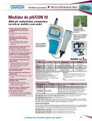
3.2 Probe information3.3 <strong>Con</strong>necting the probe to the meterYour <strong>OAKTON</strong> meter uses a conductivity/<strong>TDS</strong> cell with a sturdy 6-pin connector.This cell is designed for use with <strong>OAKTON</strong>waterproof meters only.Your meter includes a model WD-35608-50Ultem/Stainless Steel cell with a cell constantof K = 1.0. This conductivity/<strong>TDS</strong> cell featuresa built-in temperature sensor for AutomaticTemperature Compensation (ATC). It has aspecially designed housing that provides fasttemperature response and reduces air bubbleentrapment, which makes it easy to obtainaccurate, stable readings.<strong>OAKTON</strong> offers other conductivity/<strong>TDS</strong>cells with different cell constants for very highor low range readings. See the “Accessories”section on page 45 for our listing of other cells.Wetted parts include:1. Polyetherimide (Ultem)2. Polybutylterphalate (Valox)3. Stainless steel (SS 304)NOTE: We recommend that the you do notsubmerse the probe above the protective yellowcap. You can submerse the cable for briefperiods of time, but not continuously.See section 8 on page 41 for probe care andmaintenance information.1. Line up the notch and 6 pins on the meter with the holes in the 6-pin connector.Push down and turn the locking ring clockwise to lock into place.See figure below.2. To remove probe, turn the locking ring counterclockwise on the probe connector.Pull probe away from the meter.CAUTION: Do not pull on the probe cord or the probe wires might disconnect.NOTE: Keep connectors clean. Do not touch connector with soiled hands.Probe(with 6-pin connector)locking ringtop view of 6-pinconnector oftemperature probe89
4. Calibration4.1Important Information on Meter CalibrationYour meter has five measuring ranges. You can calibrate at one point in each of themeasuring ranges (up to five points). If you are measuring values in more than onerange, make sure to calibrate each of the ranges you are measuring.To view current calibration points, see SETUP section Program 2.0 on page 29.IMPORTANT: You need to calibrate your meter at a standard that is a minimumof 20% of the range in which you are measuring. For example, use a minimumcalibration value of <strong>400</strong> µS in the 0 to 1999 µS range.The following table lists the corresponding conductivity and <strong>TDS</strong> ranges. Youshould calibrate each range using a solution that falls between the values in the“recommended calibration solution range” column.<strong>Con</strong>ductivity Recommended Calibration <strong>TDS</strong> Recommended CalibrationRange Solution Range Range Solution Range4.2Preparing the Meter for CalibrationBefore starting calibration, make sure you are in the correct measurement mode.When you switch on the meter, the meter starts up in the units you shut it off in.For best results, select a standard value close to the sample value you are measuring.Alternatively use a calibration solution value that is approximately 2 ⁄3 the full scalevalue of the measurement range you plan to use. For example, in the 0 to 1999 µSconductivity range, use a 1413 µS solution for calibration.Do not reuse calibration solutions after calibration. <strong>Con</strong>taminants in the solution canaffect the calibration, and eventually the accuracy of the measurements. Use freshcalibration solution each time you calibrate your meter.NOTE: These meters are factory set to a temperature coefficient of 2.1% per °C. Formost applications this will provide good results. See Program P5.1 on page35 to set the temperature coefficient to a different value. See Addendum 3,“Calculating Temperature Coefficients” on page 50 to determine theappropriate temperature coefficient for your solution.NOTE: The factory default value for normalization temperature is 25°C. If you needto normalize to a value other than 25°C, see Program P5.2 on page 36.0.00-19.99 µS 6.00 to 17.00 µS 0.00-9.99 ppm 3.00 to 8.50 ppm0.0-199.9 µS 60.0 to 170.0 µS 10.0-99.9 ppm 30.0 to 85.0 ppm0-1999 µS 600 to 1700 µS 100-999 ppm 300 to 850 ppm0.00-19.99 mS 6.00 to 17.00 mS 1.00-9.99 ppt 3.00 to 8.50 ppt0.0-199.9 mS 60.0 to 170.0 mS 10.0-200 ppt 30.0 to 170 pptWhen you recalibrate your meter, old calibrations are replaced on a range basis.For example, if you previously calibrated your conductivity meter at 1413 µS in the0 to 1999 µS range and you recalibrate at 1500 µS (also in the 0 to 1999 µS range),the meter will replace the old calibration data (1413 µS) in that range. The meterwill retain all calibration data in other ranges.To completely recalibrate your meter, or when you use a replacement probe, it is bestto clear all calibration data in memory. To erase all old conductivity and <strong>TDS</strong> calibrationdata completely from memory, see SETUP section Program 8.0 on page 40.For information on how to calibrate your meter:• See section 4.3 on pages 12-13 for <strong>Con</strong>ductivity Calibration.(CON <strong>400</strong> and CON <strong>410</strong> meters only).• See section 4.3 on pages 14-15 for <strong>TDS</strong> Calibration.(<strong>TDS</strong> <strong>400</strong> and CON <strong>410</strong> meters only).• See section 4.4 on page 16 for Temperature Calibration.• See Addendum 1 on page 47 for more calibration tips.1011
4.3<strong>Con</strong>ductivity calibrationThe CON <strong>400</strong> and CON <strong>410</strong> meters are capable of up to 5-point conductivitycalibration at one point per conductivity range (0.00-19.99 µS; 0.0-199.9 µS;0-1999 µS; 0.00-19.99 mS; 0.0-199.9 mS).All new calibration data will over-ride existing stored calibration data for eachmeasuring range you calibrate.Calibrating for conductivity:For CON <strong>400</strong> and CON <strong>410</strong> meters only1. If necessary, press the MODE key toselect conductivity mode.See figure A2. Rinse the probe thoroughly withde-ionized water or a rinse solution,then rinse with a small amount ofcalibration standard.3. Dip the probe into the calibrationstandard. Immerse the probe tip beyondthe upper steel band. Stir the probe gentlyto create a homogeneous sample. Allowtime for the reading to stabilize.See figure B4. Press CAL/MEAS to enter conductivitycalibration mode. The CAL indicatorwill appear in the upper right corner ofthe display.5. Press the MI/▲ or MR/▼ to change thevalue on the primary display to matchthe value of the calibration standard.See figure C6. Press ENTER to confirm the calibrationvalue. The meter returns to the MEAS(measurement) mode.7. Repeat steps 1-6 for other measuringranges.ABCREADYImmerseprobe beyondupper steelbandMEASCALµSCATCµSCATCNotesWhen entering calibration mode, the meter will display the factory default value. Ifthe meter was previously calibrated, the display may “jump” to the factory defaultvalue when switching from measurement to calibration mode.To exit from <strong>Con</strong>ductivity Calibration mode without confirming calibration, DO NOTpress ENTER in step 6. Press CAL/MEAS instead. This will retain the meter’s old calibrationdata in the measuring range of the calibration.You can offset the conductivity reading up to ±20% from the default setting. If yourmeasured value differs by more than ±20%, clean or replace probe as needed.<strong>OAKTON</strong> offers a wide selection of high-quality calibration standards. See page 46for more information.1213
1. If necessary, press the MODE key toselect <strong>TDS</strong> mode.See figure A2. Rinse the probe thoroughly withde-ionized water or a rinse solution,then rinse with a small amount ofcalibration standard.3. Dip the probe into the calibrationstandard. Immerse the probe tip beyondthe upper steel band. Stir the probe gentlyto create a homogeneous sample. Allowtime for the reading to stabilize.See figure B4. Press CAL/MEAS to enter <strong>TDS</strong> calibrationmode. The CAL indicator will appear inthe upper right corner of the display.5. Press the MI/▲ or MR/▼ to change thevalue on the primary display to matchthe value of the calibration standard.See figure C6. Press ENTER to confirm the calibrationvalue. The meter returns to the MEAS(measurement) mode.7. Repeat steps 1-6 for other measuringranges.NotesTo exit from <strong>TDS</strong> Calibration mode without confirming calibration, DO NOT pressENTER in step 6. Press CAL/MEAS instead. This will retain the meter’s old calibrationdata in the measuring range of the calibration.You can offset the <strong>TDS</strong> reading up to ±20% from the default setting. If your measuredvalue differs by more than ±20%, clean or replace probe as needed.<strong>OAKTON</strong> offers a wide selection of high-quality calibration standards. See page 46for more information.144.4<strong>TDS</strong> calibration4.4.1 Calibrating for <strong>TDS</strong> directly:For <strong>TDS</strong> <strong>400</strong> and CON <strong>410</strong> meters onlyThe factory default setting for <strong>TDS</strong> converison factor is 0.5. If your solution has adifferent <strong>TDS</strong> factor, you can improve calibration accuracy by setting the <strong>TDS</strong> factorprior to calibration. See page 34 for directions.ABCREADYImmerseprobe beyondupper steelbandREADYMEASCALpptCATCpptCATC4.4.2 Calibration with <strong>Con</strong>ductivity standard and <strong>TDS</strong> factorUse this calibration method for CON <strong>410</strong> meter onlyThe concentration of salts dissolved in solution increases the conductivity of thatsolution. This relationship varies from salt to salt and is roughly linear over a givenrange for a given salt. The <strong>TDS</strong> conversion factor is the number used by the meter toconvert from conductivity to <strong>TDS</strong>.Instead of calibrating for <strong>TDS</strong> directly (described in section 4.4.1), you can calibratethe CON <strong>410</strong> meter by:1. calibrating to conductivity standards (as described on pages 12-13) and then2. entering the appropriate <strong>TDS</strong> conversion factor into the meter.To determine the conductivity to <strong>TDS</strong> conversion factor for your solution:• Addendum 2 on page 48 lists some commonly used conversion factors.• Addendum 3 on page 49 describes how to calculate the <strong>TDS</strong> conversion factor forother solutions.Enter the <strong>TDS</strong> conversion factor into your meter as follows:From measurement mode1. Press Setup key to enter Set Up mode.2. Press the ▲ and ▼ keys to scroll throughsubgroups until you view parameter P4.0.See figure A3. Press the ENTER key five times to selectparameter 4.4. The upper display shows“tdS” and the lower display shows“P4.4”.See figure B4. Press the ENTER key again. The upperdisplay shows a value and the lowerdisplay shows “tdS”.See figure C5. Calculate the <strong>TDS</strong> factor of yoursolution. See Addendum 3 on page 49for information on how to calculate the<strong>TDS</strong> factor.6. Press the ▲ and ▼ keys to select yourcalculated <strong>TDS</strong> conversion factor.7. Press the ENTER key to confirmselection and to return to the subgroupmenu. Press the CAL/MEAS key toreturn to measurement mode.ABCSETUPSETUPSETUPpptppmpptppm15
4.5Temperature CalibrationYour probe features a built-in temperature sensor. The temperature sensor is factorycalibrated. Calibrate your sensor only if you suspect temperature errors that mayhave occurred over a long period of time or if you have a replacement probe.Temperature calibration1. Make sure the cell is attached to the 6-pinconnector. The ATC annunciator willappear at the right-hand side of the LCD*.2. Switch the meter on. Press the MODEkey to select conductivity mode.3. Press the CAL/MEAS key to enter conductivityor <strong>TDS</strong> calibration mode. TheCAL indicator appears above the primarydisplay.See figure A4. While in conductivity or <strong>TDS</strong> calibrationmode, press the MODE key to enter temperaturecalibration mode. The primarydisplay shows the current temperaturereading and the secondary display showsthe factory default temperature value.See figure B5. Dip the cell into a solution of knowntemperature (i.e. a temperature bath).Allow time for the built-in temperaturesensor to stabilize.6. Scroll with the ▼ and ▲ keys to setthe correct temperature value (i.e. thetemperature of the temperature bath).You can adjust the reading in incrementsof 0.1°C.See figure C7. Once you have selected the correcttemperature, press the ENTER key.8. Press the CAL/MEAS key to return toconductivity or <strong>TDS</strong> measurement mode.NotesABCCALCALCALCµSATCCATCCATC5. MeasurementThis meter is capable of taking measurements with automatic or <strong>man</strong>ual temperaturecompensation. Factory default is ATC on.5.1Automatic Temperature CompensationFor automatic temperature compensation(ATC) simply plug the conductivity/<strong>TDS</strong>probe into the meter (see page 9 for directions).The ATC indicator will light on theLCD.See figure ANotesIf the ATC indicator does not light, <strong>man</strong>ualtemperature compensation may be selectedin the meter’s Set Up mode. See ProgramP4.3 on page 33 for directions on selectingAutomatic Temperature Compensation.AREADYMEASCµSATC16• You can offset the temperature reading up to ±5°C from the original reading.• To exit this program without confirming the temperature calibration value, DO NOTpress ENTER in step 7. Press CAL/MEAS instead.*If the ATC indicator does not light, see Program P4.3, on page 33 to switch it on.17
5.2Manual Temperature CompensationIMPORTANT: For <strong>man</strong>ual compensation, you must deactivate the temperatureprobe.5.2.1 Selecting Manual Temperature CompensationSelect between Automatic Temperature Compensation (ATC) and ManualTemperature Compensation in the Set Up Program P4.3. Meter default is ATC on.From measurement mode1. Press Setup key to enter Set Upmode.2. Press the ▲ and ▼ keys to scrollthrough subgroups until you viewparameter P4.0.See figure A3. Press the ENTER key three timesto select parameter 4.3. The upperdisplay shows “ATC” and the lowerdisplay shows “P4.3”.See figure B4. Press the ENTER key again. Theupper display shows “ATC” and thelower display shows “YES” or “NO”.See figure C5. Press the ▲ and ▼ keys to selectthe Automatic TemperatureCompensation feature on of off.• YES = ATC on• NO = ATC off6. Press the ENTER key to confirmselection and to return to the subgroupmenu. Press the CAL/MEASkey to return to measurement mode.ABCSETUPSETUPSETUPCATCCATC5.2.2 Setting a <strong>man</strong>ual temperature compensation valueTo use <strong>man</strong>ual temperature compensation, you need to enter the temperaturevalue of your process into the meter. This is the value at which readings will<strong>man</strong>ually temperature compensate. You can select any temperature between0 and 100°C (32 and 212°F). Default value is 25°C.To select a <strong>man</strong>ual temperaturecompensation value:1. Switch the meter on. Press the MODEkey to select measurement mode.2. If necessary, select ATC off as describedin section 5.2.1 on page 18. The ATCindicator will not appear on the display.3. Press the CAL/MEAS key to enterconductivity or <strong>TDS</strong> calibration mode.The CAL indicator will appear above theprimary display.See figure D4. While in conductivity or <strong>TDS</strong> calibrationmode, press the MODE key to entertemperature calibration mode. The primarydisplay shows the current temperaturesetting and the secondary displayshows the default value 25°C (77°F).See figure E5. Check the temperature of your sampleusing an accurate thermometer.6. Press the ▲ or ▼ keys to offset thetemperature to the measured valuefrom step 5.See figure F7. Press ENTER to confirm the selectedtemperature and to return to the conductivityor <strong>TDS</strong> measurement mode.The meter will now compensateconductivity or <strong>TDS</strong> readings for the<strong>man</strong>ually set temperature.DEFCALCALCALCµSCC18NotesTo exit this program without confirming the<strong>man</strong>ual temperature compensation value,DO NOT press ENTER in step 7. PressCAL/MEAS instead.19
5.3Taking Measurements5.4Using Manual Ranging FunctionTo take readings:1. Rinse the probe with deionized ordistilled water before use to removeany impurities adhering to the probebody. Shake or air dry. To avoidcontamination or dilution of yoursample, rinse probe with a smallvolume of your sample liquid.2. Press ON to switch on meter. TheMEAS annunciator appears on the topcenter of the LCD.See figure A3. Dip the probe into the sample.When dipping the probe into the sample,the tip of the probe must be immersedabove the second steel band. Stir theprobe gently in the sample to create ahomogenous sample.4. Allow time for the reading to stabilize.Note the reading on the display.5. CON <strong>410</strong> meter only: Press the MODEkey to toggle between conductivity and<strong>TDS</strong> readings.AREADYMEASCµSATCWhen shipped from the factory, your meter automatically selects the range in whichyour readings appear. The <strong>man</strong>ual ranging function lets you select the specific rangeyou want to work in:CON <strong>400</strong> and CON <strong>410</strong> meters:1. 0.00-19.99 µS;2. 0.0-199.9 µS;3. 0-1999 µS;4. 0.00-19.99 mS;5. 0.0-199.9 mS.1. To select the desired measuring range,press the RANGE key while inMeasurement mode. The first rangewill appear on the display. The“MEAS” indicator blinks.See figure A2. Press the RANGE key again (if needed)until desired range is selected.3. To reselect the Auto-ranging function,repeatedly press the RANGE key untilthe “MEAS” indicator appears withoutblinking.Notes<strong>TDS</strong> <strong>400</strong> and CON <strong>410</strong> meters:1. 0.00-9.99 ppm;2. 10.0-99.9 ppm;3. 100-999 ppm;4. 1.00-9.99 ppt;5. 10.0-200 ppt.AREADYMEASCµSATC<strong>Con</strong>ductivity range 3 (0 to 1999 µS)displayed aboveTaking measurements with READY indicator selected onIf the READY indicator has been activated, the READY annunciator lights whenthe reading is stable. Switch the READY indicator on or off in Set up programP4.1—see page 31 for directions.Taking measurements with the auto endpoint feature selected onWhen a reading is stable for more than 5 seconds, the auto endpoint feature willautomatically “hold” the reading. The “hold” indicator appears on the left side ofthe display. Press the HOLD key to release the reading. Switch the Auto endpointfeature on or off in Set up program P4.1—see page 31 for directions.If the value of the solution you are measuringis higher than the range selected “Or”will appear on the primary display. PressRANGE until the correct range is selected.See figure BThe meter resets to the Auto-rangingfunction once it is turned off. You willhave reset the <strong>man</strong>ual ranging functioneach time you turn the meter off.BREADYMEASCµSATC20 21
5.5Hold Function6. Memory and data input functionsThis feature lets you freeze the display for adelayed observation. HOLD can be usedany time when in MEAS mode.1. To hold a measurement, press theHOLD key while in measurementmode. "HOLD" will appear on thedisplay.See figure A2. To release the held value, press HOLDagain. <strong>Con</strong>tinue to take measurements.NOTE: This meter shuts off automaticallyafter 30 minutes of nonuse.If the meter is shut off eitherautomatically or <strong>man</strong>ually, theHOLD value will be lost. Forlonger storage, use the memoryfunctions (see pages 23-24).NOTE: Your meter has an auto endpointfeature. When this feature isswitched on, and when a reading isstable for more than 5 seconds, thedisplay will automatically “hold”the reading. The “hold” indicatorappears. Press the HOLD key torelease the reading. To switch on oroff the auto endpoint feature, seeSet up program P4.1 on page 31.AREADYHOLDMEASCµSATC6.1Memory InputYour meter stores up to 50 sets of data. Data sets include conductivity, temperature,date, and time.To store a reading:1. During any measurement function(MEAS), press the MI key to input anydata into the memory2. MEM, “Sto” and memory numberwill flash. The meter then returns tomeasurement mode.See figure ANOTE: If the memory is full, the first valuestored will be erased to create spacefor the new value.AMEMMEM22 2123
7.1Set-up mode overviewPress the SETUP key to enter Set up mode.Press the ▲ and ▼ keys to scroll between sub groups.Press the ENTER key to enter a particular parameter.See Addendum 5 on page 51 for a table of meter factory default settings.SETUPMEMP1.0: Memory clear• P1.0 Clear all stored readingsSETUPP5.0: Temperature• P5.1: Adjusting temperature coefficient• P5.2: Adjusting normalization temperatureC FInstructions on page 28Instructions on page 35-36SETUPInstructions on page 29P2.0: Viewing previouscalibration data• P2.1: First range calibration point• P2.2: Second range calibration point• P2.3: Third range calibration point• P2.4: Fourth range calibration point• P2.5: Fifth range calibration pointSETUPInstructions on page 37P6.0: Selecting cell constant• P6.1: Selecting cell constant:K = 1.0, 10, or 0.1SETUPP3.0: Viewing probe data• P3.1: Effective cell constant for first range• P3.2: Effective cell constant for second range• P3.3: Effective cell constant for third range• P3.4: Effective cell constant for fourth range• P3.4: Effective cell constant for fifth rangeSETUPP7.0: Setting clock• Setting year• Setting date (month/day)• Setting time (hour/minute/second)Instructions on page 30Instructions on page 38-39SETUPInstructions on page 31-34P4.0: Unit configuration• P4.1: Ready indicator and auto endpointfunction—select on or off• P4.2: Select °C or °F• P4.3 Select Automatic or ManualTemperature Compensation• P4.4 Setting <strong>TDS</strong> conversion factor(<strong>TDS</strong> <strong>400</strong> and CON <strong>410</strong> meters only)SETUP MEASInstructions on page 40P8.0: Reset to factory defaultsP8.0: reset meter to factory defaults2627
7.2P1.0: Memory Clear7.3P2.0: Viewing calibration dataUse this parameter to clear all memory values when you need to store a new series ofvalues. This lets you avoid confusing the old values with the new ones. NO is thedefault setting.NOTE: Selecting YES will wipe out all memory.From measurement mode:1. Press the Set up key to enter Set Upmode.2. Press the ▲ and ▼ keys to scroll throughsubgroups until you view parameter P1.0.See figure A3. Press the ENTER key to enter parameterP1.0.4. Press the ▲ and ▼ keys to togglebetween NO and YES.• NO retains current memory• YES clears all memorySee figure B5. Press the ENTER key to confirm selectionand return to the subgroup menu.Press the CAL/MEAS key to return tomeasurement mode.ABSETUPSETUPMEMMEMThis mode lets you recall previous calibration data, which helps you know when torecalibrate your meter. This is a “view only” mode.From measurement mode:1. Press the Set up key to enter Set Upmode.See figure A2. Press the ▲ and ▼ keys to scroll throughsubgroups until you view parameterP2.0.3. Press the ENTER key repeatedly toview previous calibration data. Themeter will first display the calibrationpoint, and then display the date and timeof calibration to help you comply withGLP standards.See figures B and C4. When you have scrolled through allcalibration data, you will automaticallyreturn to the subgroup menu. Press theCAL/MEAS key to return to measurementmode.NotesABSETUPSETUPSETUPCALCalibration dataµSIf there is no previous calibration data at aparticular point, the primary display willshow “----”.CON <strong>410</strong> meter only: If you entered Set Upmode from <strong>Con</strong>ductivity measurementmode, calibration data will be in µS or mS.If you entered Set Up mode from <strong>TDS</strong>measurement mode, calibration data willbe in ppm or ppt.CAMdate/time2829
7.4From measurement mode:1. Press the Set up key to enter Set Upmode.See figure A2. Press the ▲ and ▼ keys to scrollthrough subgroups until you viewparameter P3.0.3. Press the ENTER key repeatedly toview the effective cell constant for eachrange.See figure B4. When you have scrolled through allprobe data, you will automaticallyreturn to the subgroup menu. Pressthe CAL/MEAS key to return tomeasurement mode.NotesP3.0: Viewing probe dataProgram 3 has five "view only" options that let you check your probe’s parameters fordiagnostic purposes. These options show you the effective cell constant for each range.The cell constant is adjusted according to your calibration.Cell constants will degrade with time andusage. You can use this feature to alert youto the need for a new probe prior to totalfailure.ABSETUPSETUP7.5P4.0: Unit configurationP4.1: READY indicator and auto endpoint functionProgram P4.1 lets you select “READY indicator on” to indicate when your measurementis stable, or select “READY indicator off” for faster meter response.Program P4.1 also lets you switch the Auto endpoint function on or off. Select autoendpoint on to “hold” your measurement when it is stable for more than 5 seconds.The display automatically freezes, and the HOLD indicator appears on the left sideof the display. Press the HOLD key to release the display and access other functions.Select auto endpoint off to deactivate this feature.From measurement mode1. Press Setup key to enter Set Up mode.2. Press the ▲ and ▼ keys to scroll throughsubgroups until you view parameter P4.0.See figure A3. Press the ENTER key to selectparameter 4.1.See figure B4. Press the ▲ and ▼ keys to select theconfiguration you require.• OFF switches the READY indicator off.• ON switches the READY indicator on.• ON and HOLD together switches theauto endpoint feature on.5. Press the ENTER key to confirm selectionand to proceed to step 4 of P.4.2. Press theCAL/MEAS key to return to measurementmode.ABSETUPSETUPREADYONNotesMeter default is set for Ready indicator on,and auto endpoint function off.3031
P4.2 Selecting °C or °FYou can select between °C and °F units for temperature readings. Meter default is °C.P4.3 Selecting Automatic or Manual Temperature CompensationThis feature lets you select between Automatic Temperature Compensation (ATC)and Manual Temperature Compensation. Meter default is ATC.From measurement mode1. Press Setup key to enter Set Up mode.2. Press the ▲ and ▼ keys to scroll throughsubgroups until you view parameter P4.0.See figure C3. Press the ENTER key two times toselect parameter 4.2.See figure D4. Press the ▲ and ▼ keys to togglebetween °C and °F.5. Press the ENTER key to confirm selectionand to proceed to step 3 of P.4.3.Press the CAL/MEAS key twice toreturn to measurement mode.CDSETUPSETUPFFrom measurement mode1. Press Setup key to enter Set Up mode.2. Press the ▲ and ▼ keys to scrollthrough subgroups until you viewparameter P4.0.See figure E3. Press the ENTER key three times toselect parameter 4.3. The upper displayshows “ATC” and the lower displayshows “P4.3”.See figure F4. Press the ENTER key again. The upperdisplay shows “ATC” and the lowerdisplay shows “YES” or “NO”.EFSETUPSETUPCATCSee figure G5. Press the ▲ and ▼ keys to select theAutomatic Temperature Compensationon of off.• YES = ATC on• NO = ATC off6. Press the ENTER key to confirmselection and to return to the subgroupmenu. Press the CAL/MEAS key toreturn to measurement mode.GSETUPCATC3233
P4.4 Setting the <strong>TDS</strong> factorFor <strong>TDS</strong> <strong>400</strong> and CON <strong>410</strong> meters onlyThe concentration of salts dissolved in solution increases the conductivity of thatsolution. This relationship varies from salt to salt and is roughly linear over a givenrange for a given salt. The <strong>TDS</strong> conversion factor is the number used by the meter toconvert from conductivity to <strong>TDS</strong>.To determine the conductivity to <strong>TDS</strong> conversion factor for your solution:• Addendum 2 on page 48 lists some commonly used conversion factors.• Addendum 3 on page 49 describes how to calculate the <strong>TDS</strong> conversion factor forother solutions.You can set the <strong>TDS</strong> conversion factor between 0.4 and 1.0; meter default is 0.5.From measurement mode1. Press Setup key to enter Set Up mode.2. Press the ▲ and ▼ keys to scrollthrough subgroups until you viewparameter P4.0.See figure H3. Press the ENTER key five times toselect parameter 4.4. The upper displayshows “tdS” and the lower displayshows “P4.4”.See figure I4. Press the ENTER key again. The upperdisplay shows a value and the lowerdisplay shows “tdS”.See figure J5. Calculate the <strong>TDS</strong> factor of yoursolution. See Addendum 3 on page 49for information on how to calculate the<strong>TDS</strong> factor.6. Press the ▲ and ▼ keys to select yourcalculated <strong>TDS</strong> conversion factor.7. Press the ENTER key to confirmselection and to return to the subgroupmenu. Press the CAL/MEAS key toreturn to measurement mode.HIJSETUPSETUPSETUPpptppmpptppm7.6P5.0: TemperatureP5.1 Adjusting the temperature coefficientThe temperature coefficient is the amount of change in conductivity per degree oftemperature; it is expressed in percent per °C or °F. Entering the exact temperaturecoefficient of your solution lets you accurately compensate temperature for almostany solution*. You can adjust 0.0 to 10.0% per °C or °F. Meter default is 2.1% per °Cor °F.From measurement mode1. Press Setup key to enter Set Up mode.2. Press the ▲ and ▼ keys to scroll throughsubgroups until you view parameter P5.0.See figure A3. Press the ENTER key to selectparameter 5.1. The display shows“T.CO” on the upper display.See figure B4. Press the ENTER key again.. The upperdisplay shows the temperature coefficientand the lower display shows “T.CO”.See figure C5. Press the ▲ and ▼ keys to select the temperaturecoefficient of your solution.6. Press the ENTER key to confirm selectionand to proceed to step 3 of P.5.2.Press the CAL/MEAS key twice to returnto measurement mode.Notes* If you do not know the temperature coefficientof your solution you can determinethe correct value using the formula inAddendum 3 “Calculating TemperatureCoefficients” on page 50.ABCSETUPSETUPSETUPC FC F3435
P5.2 Adjusting the normalization temperatureYour meter will normalize its conductivity measurements to a standard temperaturethat you can select. You can adjust the normalization temperature from 15 to 30°C(59 to 86°F). Meter default is 25°C (77°F).From measurement mode1. Press Setup key to enter Set Up mode.2. Press the ▲ and ▼ keys to scroll throughsubgroups until you view parameter P5.0.See figure D3. Press the ENTER key three times toselect parameter 5.2. The display shows“t.nr” on the upper display.See figure E4. Press the ENTER key again. Theupper display shows the normalizationtemperature and the lower displayshows “t.nr”.See figure F5. Press the ▲ and ▼ keys to select thenormalization temperature.6. Press the ENTER key to confirm selectionand to return to the subgroup menu.Press the CAL/MEAS key to return tomeasurement mode.DEFSETUPSETUPSETUPC FC FC7.7P6.0: Selecting the cell constantYour meter lets you select a cell constant of K = 1.0, 10, or 0.1.• Use a cell of K = 1.0 for midrange measurements• Use a cell of K = 10 for high range measurements (above 20 mS or 10 ppt)• Use a cell of K = 0.1 for low range measurements (below 20 µS or 10 ppm).The cell included with your meter has a cell constant of K = 1.0. Order cells with acell constant of K = 10 or 0.1 on page 45.From measurement mode1. Press Setup key to enter Set Up mode.2. Press the ▲ and ▼ keys to scroll throughsubgroups until you view parameter P6.0.See figure A3. Press the ENTER key to selectparameter 6.1.See figure B4. Press the ▲ and ▼ keys to select thebetween K = 1.0, 0.1, or 10.5. Press the ENTER key to confirm selectionand to return to the subgroup menu. Pressthe CAL/MEAS key to return to measurementmode.NotesWhen using a cell of K = 0.1, the lowestmeasuring range will be:• 0 to 1.999 µS (0 to 0.999 ppm).The 0 to 199.9 mS (10 to 200 ppt) range willnot be accessible.When using a cell of K = 10, the highestmeasuring range will be:• 0 to 1999 mS (100 to 2000 ppt).The 0 to 19.99 µS (0.00 to 9.99 ppm) rangewill not be accessible.ABSETUPSETUP3637
7.8P7.0: Setting the clockYour meter features a real-time calendar and clock. This helps you meet GLP (GoodLaboratory Practice) standards.11. Press the ENTER key to confirm thedate and move to “hour” selection.The “hour” digits will flash.See figure FSETUPFrom measurement mode1. Press Setup key to enter Set Up mode.SETUP12. Press the ▲ and ▼ keys to toggle tothe correct hour. Note the “AM” and“PM” indicator on the lower portionof the display.FAM2. Press the ▲ and ▼ keys to scroll throughsubgroups until you view parameterP7.0.See figure A3. Press the ENTER key to enterparameter P7.0. The meter lets youselect the century: “19-” or “20-”.The century digits will flash.See figure B4. Press the ▲ and ▼ keys to toggle to thecorrect century.5. Press the ENTER key to confirm thecentury and move to “year” selection.The “year” digits will flash.See figure C6. Press the ▲ and ▼ keys to toggle to thecorrect year.7. Press the ENTER key to confirm theyear and move to “month” selection.The “month” digits will flash.See figure D8. Press the ▲ and ▼ keys to toggle to thecorrect month.9. Press the ENTER key to confirm themonth and move to “date” selection.The “date” digits will flash.ABCDSETUPSETUPSETUP13. Press the ENTER key to confirm thehour and move to “minute” selection.The “minute” digits will flash.See figure G14. Press the ▲ and ▼ keys to toggle tothe correct minutes.15. Press the ENTER key to confirm theminutes and move to “second” selection.The “second” digits will flash.See figure H16. Press the ▲ and ▼ keys to toggle tothe correct seconds.17. Press the ENTER key to confirmthe seconds and return to “century”selection.18. Press the CAL/MEAS key to returnto the subgroup menu. Press theCAL/MEAS key again to return tomeasurement mode.NotesPress the CAL/MEAS key at any pointwhile setting the time to return to thesubgroup menu.GHSETUPSETUPAMAMSee figure E10. Press the ▲ and ▼ keys to toggle tothe correct date.SETUPcontinued on next pageE3839
7.9P8.0: Resetting to factory default settingsProgram 8.0 lets you reset all parameters to factory default settings. This clears allcalibration data, memory, and any other setup functions you might have changed.It does not clear clock settings.From measurement mode1. Press Setup key to enter Set Up mode.2. Press the ▲ and ▼ keys to scroll throughsubgroups until you view parameterP8.0.See figure A3. Press the ENTER key to enterparameter P8.0.See figure B4. Press the ▲ and ▼ keys to togglebetween NO and YES.• NO retains current settings• YES resets to factory default settings5. Press the ENTER key to confirm selectionand to return to the subgroup menu.Press the CAL/MEAS key to return tomeasurement mode.NotesABSETUPSETUPMEASMEAS8. Probe Care and MaintenanceKeep the conductivity probe clean. Rinse the probe twice, and gently swirl it whileyou take readings. For best accuracy, soak a dry probe for at least 5 to 10 minutes orlonger before calibration. Rinse the probe with deionized or tap water before storing.Never scratch the platinum portions with a hard substance. Do not strike the probeagainst any hard surface.Do not make continuous contact with your solutions. Readings will rise over aperiod of time while you soak your probe.Do not immerse the probe in oily solutions. Clean the electrode thoroughly bystirring it in a mild detergent bath or isopropyl alcohol. Wipe the probe with a softtissue paper. Rinse thoroughly in tap water and then in deionized water. Recalibratethe meter after cleaning the probe.The model WD-35608-50 probe (included with your meter) features a removableprobe guard to make cleaning easy.To remove probe guard:1. Grip yellow probe guard and twistclockwise. The locking notch will release.2. Slide probe guard off end of probe.Probe modelWD-35608-50locking notchSee Addendum 5 on page 51 for a table offactory default settings.twist probeguard clockwiseto remove4041
9. TroubleshootingProblem Cause SolutionPower on but a) Batteries not in place. a) Check that batteries are inno displayplace and making goodcontact.b) Batteries not in correct b) Reinsert batteries withpolarity (+ and –).correct polarity.c) Weak batteries. c) Replace batteries or attachoptional AC adapter.Unstable a) Air bubbles in probe. a) Tap probe to remove bubbles.readingsb) Dirty probe. b) Clean the probe andrecalibrate.c) Probe not deep c) Make sure sample entirelyenough in sample.covers the probe sensors.d) External noise pickup d) Move or switch offor induction caused byinterfering motor.nearby electric motor.e) Broken probe. e) Replace probe. See page 45.Slow response a) Dirty/Oily probe. a) Clean probe. See "ProbeCare & Maintenance",page 41.10. Error MessagesLCD Indicates Cause SolutionDisplayErr Unrecognized input Wrong input in Release key. Selectannunciator from keypad selected mode. valid operationsdepending on mode.CAL & Err Calibration error Wrong buffer value Check your calibrationannunciators on/ input at calibration. input value, clean probe.Buffer and Dirty probe. See Calibration sections orelectrodeProbe Maintenance section.indicators blinkBattery Low battery level Need new batteries Clean battery contacts.indicator blinks or battery Replace batteries with freshconnection is bad ones, noting polarityErr. 1 Memory write Hardware failure. Turn meter on and off(in primary error again. If message persists,display)return unit*Err. 2 Memory checksum Hardware failure. Turn meter on and off(in primary error again. If message persists,display)return unit*Err. 3 ACD converter Hardware failure. Turn meter on and off(in primary error again. If message persists,display)return unit*Err. 4 Keypad error Fault in keypad Turn meter on and off(in primaryagain. If message persists,display)return unit** See "Warranty" and "Return of Items" on page 52.If an error message appears in the primarydisplay (the upper row of larger digits),switching off the meter and switching it onagain may eliminate the error message.See figure AIf error persists, or the meter showsincorrect values, return the meter.For a complete diagram of the display,see page 5.AERR 1 in primary display4243
11. SpecificationsMode<strong>Con</strong>ductivity<strong>TDS</strong>(CON <strong>400</strong> & <strong>410</strong> meters) (<strong>TDS</strong> <strong>400</strong> & CON <strong>410</strong> meters)Temperature0.00 to 19.99 µS (0.01 µS) 0.00 to 9.99 ppm (0.01 ppm)0.0 to 199.9 µS (0.1 µS) 10.0 to 99.9 ppm (0.1 ppm) 0.0 to 100.0°CRange 0 to 1999 µS (1 µS) 100 to 999 ppm (1 ppm) or(Resolution) 0.00 to 19.99 mS (0.01 mS) 1.00 to 9.99 ppt (0.01 ppt) 32.0 to 212.0°F0.0 to 199.9 mS (0.1 mS) 10.0 to 200 ppt (0.1/1 ppt) (0.1°C or °F)Accuracy ±1% full scale ±1% full scale ±0.5°C or °FCell constant: 1.0, 0.1, or 10 selectable (cell constant of included cell = 1.0)Temperature compensation: Automatic or <strong>man</strong>ual 0 to 50°C (32 to 122°F)Temperature coefficient: 0 to 10% per °C or °F<strong>TDS</strong> factor: adjustable from 0.4 to 1.0Operating temperature: 0 to 50°C (32 to 122°F)Memory: up to 50 points (includes measurement, temperature, date and time)Real time clock: stamps calibration data and stored data with time and date (monthand day)Power: 4 x 1.5 V AAA batteries (>100 hours)Dimensions: 7.5"L x 3.5"W x 1.75"H (meter only); 9.2"L x 9.2"W x 2.75"H (boxed)Weight: 1.0 lb (meter only); 2.0 lbs (boxed complete)12. AccessoriesReplacement metersWD-35608-00 Replacement waterproof CON <strong>400</strong> meterWD-35608-05 Replacement waterproof <strong>TDS</strong> <strong>400</strong> meterWD-35608-10 Replacement waterproof CON <strong>410</strong> meterWD-35607-60 Calibration kit. Includes 60 ml each of four calibration solutions:84 µS, 447 µS, 15,000 µS, and and 80 mS; squirt bottle with 120 ml deionized water,and empty 60 ml sample bottle— all in a hard shell carrying case.ProbesWD-35608-50 Replacement conductivity/<strong>TDS</strong> cell. Ultem/Stainless Steel withbuilt-in temperature sensor. Cell constant = 1.0WD-35608-51 <strong>Con</strong>ductivity/<strong>TDS</strong> cell. Epoxy body with built-in temperature sensor.Cell constant = 10WD-35608-55 <strong>Con</strong>ductivity/<strong>TDS</strong> cell. Epoxy body with built-in temperature sensor.Cell constant = 0.1<strong>Con</strong>tinued on next page4445
<strong>OAKTON</strong> conductivity/<strong>TDS</strong> calibration solution bottlesOur solutions come in 1 pint recyclable PE bottles. ±1% accuracy at 25°C.Shpg wt 1.1 lb (510 g).<strong>TDS</strong> calibration valuesModel No. Solution typeppm KCl ppm NaCl ppm 442WD-00653-16 84 µS 40.38 38.04 50.50WD-00653-47 447 µS 225.6 215.5 300.0WD-00653-18 1413 µS 744.7 702.1 1000WD-00653-15 1500 µS 757.1 737.1 1050WD-00653-89 8974 µS 5101 4487 7608WD-00606-10 12,880 µS 7447 7230 11,367WD-00653-50 15,000 µS 8759 8532 13,455WD-00653-32 80 mS 52,168 48,384 79,688<strong>OAKTON</strong> conductivity/<strong>TDS</strong> calibration solution pouchesEach pouch contains 20 ml of fresh, premixed calibration solution—guaranteesuncontaminated solution for every use. ±1% accuracy at 25°C. 20 pouches/box.Shpg wt 1.1 lb (510 g).13. Addendum 1: Calibration TipsYou only need one calibration for measurement throughout the entire range of themeter. If a range was not calibrated, the meter automatically detects the closest rangecalibrated and uses that calibration information. However, only the ranges that werecalibrated have maximum accuracy.• If you are measuring in ranges near to or greater than 20 mS (10 ppt), or near to orlower than 100 µS (50 ppm), calibrate the meter at least once a week to get specified±1% F.S. accuracy.• If you are measuring in the mid ranges and you washed the probe in deionizedwater and stored it dry, calibrate the meter at least once a month.Wet the probe for 10 minutes before calibrating or taking readings to saturate theprobe surface and minimize drift. If you make measurements at extreme temperatures,calibrate the meter at least once a week.You should only use the conductivity/<strong>TDS</strong> probe specified for these meters. Theseprobes have a built-in temperature sensor. If you use a different probe without atemperature sensor, you must measure the solution temperature separately and<strong>man</strong>ually enter the solution temperature (see <strong>man</strong>ual temperature compensation onpages 18-19).<strong>Con</strong>ductivity-to-<strong>TDS</strong> calibration valuesModel No. Solution typeppm KCl ppm NaCl ppm 442WD-35653-10 447 µS 225.6 215.5 300.0WD-35653-11 1413 µS 744.7 702.1 1000WD-35613-13 15,000 µS 8759 8532 13,455WD-35653-00 Deionized rinse water pouches. 20 pouches/box.To order <strong>OAKTON</strong> accessories, contact your <strong>OAKTON</strong> distributor.4647
4815. Addendum 3: Calculating <strong>TDS</strong> <strong>Con</strong>version FactorsYou can calibrate your meter using <strong>TDS</strong> calibration standard solutions. The calibrationstandard only needs to give the <strong>TDS</strong> value at a standard temperature such as25°C. To determine to the conductivity-to-<strong>TDS</strong> conversion factor use the followingformula:Factor = Actual <strong>TDS</strong> ÷ Actual <strong>Con</strong>ductivity @ 25°CDefinitions:Actual <strong>TDS</strong>: Value from the solution bottle label or as a standard you make usinghigh purity water and precisely weighed salts.Actual <strong>Con</strong>ductivity: Value measured using a properly calibrated <strong>Con</strong>ductivity/Temperature meter.Both the Actual <strong>TDS</strong> and the Actual <strong>Con</strong>ductivity values must be in the samemagnitude of units. For example, if the <strong>TDS</strong> value is in ppm the conductivity valuemust be in µS; if the <strong>TDS</strong> value is in ppt the conductivity value must be in mS.Check your factor by multiplying the conductivity reading by the factor in the aboveformula. The result should be the <strong>TDS</strong> value.4914. Addendum 2: <strong>Con</strong>ductivity to <strong>TDS</strong> <strong>Con</strong>version Factors1. Factor—the conductivity to ppm <strong>TDS</strong> conversion factor. Multiply conductivity by this factor to get ppm <strong>TDS</strong> for the type of <strong>TDS</strong>reading needed.2. 442—a formulation that most closely represents the conductivity to ppm relationship, on average, for naturally occurring freshwater.3. <strong>TDS</strong> Your Material—These columns are for you to write in your application-specific conductivity-to-ppm values and conversionfactors for future reference.Factor = actual <strong>TDS</strong> ÷ Actual <strong>Con</strong>ductivity @ 25°C<strong>Con</strong>ductivity <strong>TDS</strong> KCl <strong>TDS</strong> NaCl <strong>TDS</strong> 442 2 <strong>TDS</strong> Your Material 3at 25°C ppm Factor 1ppm Factor 1ppm Factor 1ppm FactorValue Value Value Value84 µS 40.38 0.5048 38.04 0.4755 50.50 0.6563447 µS 225.6 0.5047 215.5 0.4822 300.0 0.67121413 µS 744.7 0.5270 702.1 0.4969 1000 0.70781500 µS 757.1 0.5047 737.1 0.4914 1050 0.70008974 µS 5101 0.5685 4487 0.5000 7608 0.847812880 µS 7447 0.5782 7230 0.5613 11,367 0.882515000 µS 8759 0.5839 8532 0.5688 13,455 0.897080 mS 52,168 0.6521 48,384 0.6048 79,688 0.9961
16. Addendum 4: Calculating Temperature CoefficientsTo determine the temperature coefficient of your sample solution use this formula:C T2 - CTC = 100 x _________________________T1C T1 (T 2 - 25) - C T2 (T 1 - 25)TC = Temperature coefficientC T1 =<strong>Con</strong>ductivity at Temp. 1 C T2 = <strong>Con</strong>ductivity at Temp. 2T 1 = Temp. 1 T 2 = Temp. 2 25 = 25°CNOTE: A controlled temperature water bath is ideal for this procedure.1. Immerse the probe into a sample of your solution and adjust the temperaturecoefficient to 0% (that is, no compensation) by performing the following:A. From measurement mode, press the SETUP key to enter Setup mode.B. Press the ▼ key until the lower display reads P5.0.C. Press the ENTER key twice. The lower display reads tCO and the upperdisplay shows the temperature coefficient value.D. Press the ▼ key until the upper display shows 0.0.E. Press ENTER key to confirm the value.F. Press CAL/MEAS key twice to return to measurement mode.2. Wait for 5 minutes. Note T 1 and C T1 (conductivity at T 1 ).3. <strong>Con</strong>dition the sample solution and probe to a temperature (T 2 ) that is about 5°Cto 10°C different from T 1 , and note the conductivity reading C T2 .NOTE: Record your results for future reference. Ideally T 1 and T 2 should bracketyour measurement temperature, and should not differ by more than 5°C.4. Calculate the temperature coefficient of your solution according to the formulashown above.5. Enter the temperature coefficient you calculated into the meter.A. From measurement mode, press the SETUP key to enter Setup mode.B. Press the ▼ key until the lower display reads P5.0.C. Press the ENTER key twice. The lower display reads tCO and the upperdisplay shows the temperature coefficient value (should be 0, per step 1above).D. Press the ▲ key until the upper display shows your calculated temperaturecoefficient.E. Press ENTER key to confirm the value.F. Press CAL/MEAS key twice to return to measurement mode.The calculated temperature coefficient will now be applied to all the meter readings.17. Addendum 5: Meter factory default settingsType Parameter Default RemarksP1.0 Memory clear no Retains current memoryP2.1 Viewing previous – – – No calibration data for 1st rangeP2.2calibration data– – – No calibration data for 2nd rangeP2.3 – – – No calibration data for 3rd rangeP2.4 – – – No calibration data for 4th rangeP2.5 – – – No calibration data for 5th rangeP3.1 Viewing 1.0 No offset for effective cell constant (1st range)P3.2probe data1.0 No offset for effective cell constant (2nd range)P3.3 1.0 No offset for effective cell constant (3rd range)P3.4 1.0 No offset for effective cell constant (4th range)P3.5 1.0 No offset for effective cell constant (5th range)P4.1 Ready indicator/auto endpoint READY/ON Ready indicator on; auto endpoint offP4.2 Select °C/°F °C Degrees CelsiusP4.3 ATC on or off ATC on —P4.4 <strong>TDS</strong> factor 0.5 Adjustable from 0.4 to 1.0(available in <strong>TDS</strong> <strong>400</strong> and CON <strong>410</strong> meters only)P5.1 Temp. coefficient 2.1% per °C Adjustable from 0 to 10%P5.2 Normalizationtemperature 25°C Adjustable from 15 to 30°CP6.1 Cell constant 1.0 Select from K = 1.0, 0.1 or 10P8.0 Factory default no Retains your current settingsNotesThe P7.0 clock function retains the year and time that you set, even after reverting tofactory default settings.5051