Manual for DO 6 - Oakton Instruments
Manual for DO 6 - Oakton Instruments
Manual for DO 6 - Oakton Instruments

Create successful ePaper yourself
Turn your PDF publications into a flip-book with our unique Google optimized e-Paper software.
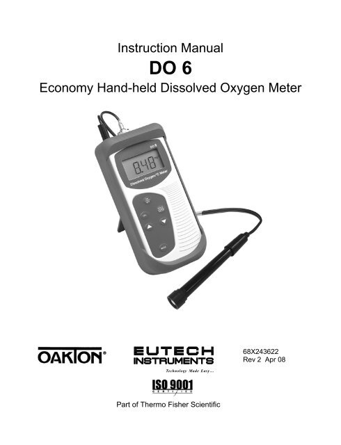
Instruction <strong>Manual</strong><strong>DO</strong> 6Economy Hand-held Dissolved Oxygen MeterTechnology Made Easy ...68X243622Rev 2 Apr 08Part of Thermo Fisher Scientific
PrefaceThis manual serves to explain the use of the <strong>DO</strong> 6 Dissolved Oxygen Handheld.This manual functions in two ways: first as a step by step guide to help youoperate the meter; second, as a handy reference guide.This manual is written to cover as many anticipated applications of the <strong>DO</strong>6palm-top meter as possible. If there are doubts in the use of the DissolvedOxygen Handheld, please do not hesitate to contact the nearest Eutech<strong>Instruments</strong> / <strong>Oakton</strong> <strong>Instruments</strong> authorized Distributor.Eutech <strong>Instruments</strong>/<strong>Oakton</strong> <strong>Instruments</strong> will not accept any responsibility <strong>for</strong>damage or malfunction to the meter caused by improper use of the instrument.The in<strong>for</strong>mation presented in this manual is subject to change without notice asimprovements are made, and does not represent a commitment on the part ofEutech <strong>Instruments</strong> / <strong>Oakton</strong> <strong>Instruments</strong>.Copyright © 2004Eutech <strong>Instruments</strong> Pte Ltd<strong>Oakton</strong> <strong>Instruments</strong>All rights reserved.
TABLE OF CONTENTS1 INTRODUCTION ..........................................................................12 DISPLAY & KEYPAD FUNCTIONS.............................................22.1 DISPLAY .................................................................................22.2 KEYPAD..................................................................................33 PREPARATION............................................................................43.1 INSERTING & REMOVING RUBBER BOOT ................................43.2 INSERTING THE BATTERIES.....................................................53.3 BATTERY REPLACEMENT........................................................63.4 DISSOLVED OXYGEN PROBE INFORMATION............................73.5 CONNECTING THE PROBE TO METER ......................................93.6 SWITCHING THE METER ON..................................................103.7 MEASUREMENT MODE SELECTION:- PERCENTAGESATURATION (%), CONCENTRATION (MG/L)(PPM) ANDTEMPERATURE(T).................................................................114 CALIBRATION ...........................................................................124.1 IMPORTANT INFORMATION ON METER CALIBRATION...........124.2 PREPARING THE METER FOR CALIBRATION ..........................134.3 TEMPERATURE CALIBRATION...............................................154.4 DISSOLVED OXYGEN CALIBRATION IN % SATURATION........174.4.1 To calibrate 100% Saturation:................................................ 174.4.2 To calibrate 0% Saturation..................................................... 194.5 DISSOLVED OXYGEN CALIBRATION IN MG/L OR PPMCONCENTRATION MODE ........................................................204.5.1 To calibrate in mg/L (ppm) Concentration mode:................... 205 MEASUREMENT........................................................................225.1 WITH AUTOMATIC TEMPERATURE COMPENSATION (ATC)..225.2 MANUAL TEMPERATURE COMPENSATION ............................235.3 TAKING MEASUREMENTS .....................................................255.3.1 To take measurements: ......................................................... 25
5.4 TAKING PRESSURE/SALINITY COMPENSATED <strong>DO</strong>MEASUREMENTS...................................................................265.4.1 Pressure Setting Adjustment.................................................. 265.4.2 Salinity Setting Adjustment .................................................... 296 HOLD FUNCTION ......................................................................307 ADVANCED SETUP FUNCTIONS.............................................317.1 ADVANCED SETUP OVERVIEW..............................................317.1.1 To enter the % Saturation or Temperature Set Up menu: ..... 317.1.2 To enter the mg/L (ppm) Concentration Set Up menu: .......... 317.2 (COF.1) CONFIGURATION MENU..........................................367.2.1 Selection of Automatic Temperature Compensation.............. 367.2.2 Selection of mg/L or ppm mode ............................................. 387.3 (CAL.2) CALIBRATION DATA...............................................397.3.1 Viewing the % Saturation calibration data.............................. 397.3.2 Viewing the mg/L (ppm) Concentration calibration data ........ 397.4 (ELE.3) ELECTRODE PROPERTIES.........................................407.4.1 Viewing the electrode Slope Factor ....................................... 407.4.2 Viewing the % Saturation Offset (Only available in %Saturation or Temperature Set Up menu):............................................... 407.4.3 Viewing the 100% Saturation mV value ................................. 417.4.4 Viewing the 0% Saturation mV value ..................................... 417.5 (ATO.4) AUTOMATIC OFF ....................................................437.6 (RST.5) RESET TO FACTORY DEFAULT..................................447.6.1 Calibration Reset.................................................................... 447.6.2 User Reset ............................................................................. 467.7 (OFS.6) % SATURATION OFFSET ADJUSTMENT....................477.8 (DPR.7) DISSOLVED OXYGEN PARAMETERS.........................497.8.1 Pressure Setting Adjustment.................................................. 497.8.2 Salinity Setting Adjustment .................................................... 518 PROBE CARE AND MAINTENANCE........................................528.1 PROBE CARE.........................................................................538.2 PRE-MEMBRANED CAPS REPLACEMENT...............................538.3 TO REPLACE THE PROBE PRE-MEMBRANED CAP ....................54
8.4 ELECTROLYTE SOLUTION .....................................................559 TROUBLE-SHOOTING GUIDE..................................................5610 ERROR MESSAGES..................................................................5711 FACTORY DEFAULT SETTINGS..............................................5812 SPECIFICATIONS......................................................................6013 ACCESSORIES..........................................................................6214 ADDITIONAL INFORMATION....................................................6314.1 DISSOLVED OXYGEN ............................................................6314.1.1 General In<strong>for</strong>mation ............................................................... 6314.1.2 Measurement Units ................................................................ 6514.1.3 What Is Being Measured?...................................................... 6514.1.4 Air Calibration......................................................................... 6614.1.5 Applications............................................................................ 6615 WARRANTY...............................................................................6816 RETURN OF ITEMS ...................................................................69
Instruction <strong>Manual</strong> <strong>DO</strong> 61 INTRODUCTIONThank you <strong>for</strong> purchasing the <strong>DO</strong> 6 Dissolved Oxygen Handheld. This economymicroprocessor-based handheld has a large custom LCD (Liquid CrystalDisplay) <strong>for</strong> clear and easy reading.The <strong>DO</strong> 6 offers the measurement of dissolved oxygen in the percentagesaturation mode and in the concentration mode. Temperature measurement isalso available in degrees Celsius. The meter ensures accurate measurement ofthe Dissolved Oxygen values through its temperature, barometric pressure andsalinity compensation features.Your meter includes a dissolved oxygen probe, refill solution, a rubber boot, 4alkaline “AAA” batteries, and instruction manual.Please read this manual thoroughly be<strong>for</strong>e operating your meter.To order other accessories and standard solutions, please refer to the Sectionon Accessories <strong>for</strong> more in<strong>for</strong>mation.1
Instruction <strong>Manual</strong> <strong>DO</strong> 62 DISPLAY & KEYPAD FUNCTIONS2.1 DisplayThe meter has a large custom LCD that consists of 14-segment 4 digit displayand operation annunciators <strong>for</strong> Percentage Saturation measurement mode (%),Concentration measurement mode (mg/L or ppm) and Temperaturemeasurement mode in degrees Celsius (T). Other annunciators include “A”(when the ATC function is activated), “CAL” (when meter is in calibration mode)and battery diagram <strong>for</strong> low battery condition. See Figure 1.Calibration ModeAnnunciatorCALLow Battery annunciatorTemperature ModeTAmg/lppm%A T C annunciatormilligram per litre(Concentration Mode)parts per million14-segment Liquid Crystal DisplayPercentage(Percentage SaturationMode)Figure 1: Active LCD display <strong>for</strong> <strong>DO</strong> 62
Instruction <strong>Manual</strong> <strong>DO</strong> 62.2 KeypadThe <strong>DO</strong> 6 meter has 6 keys on its splash-proof keypad; ON/OFF,HOLD/ENTER CAL, MODE, ▲ and ▼ keys. Some buttons have severalfunctions depending on its mode of operation.ONOFFON/OFF – Powers on and shuts off the meter. The meter will start in themeasurement mode it was in when last switched off.CALCAL – Activates the calibration mode <strong>for</strong> Percentage Saturation,Concentration and Temperature calibrations.Deactivates calibration or setup without confirming a value in calibrationmode.HOLDENTERHOLD -Activates/Deactivates freezing of the measured reading while inmeasurement mode.ENTER - Confirms the calibration values in Calibration mode and theselections in the SETUP menu.▲▼ – Sets the calibration values during the Concentration andTemperature calibration.Scrolls through each SETUP and its sub group menu.Set offset adjustments and configuration settings.MODEMODE - Selects the measurement option between <strong>DO</strong> PercentageSaturation measurement; <strong>DO</strong> Concentration measurement andTemperature measurement.When pressed together with ON/OFF key during power on, SETUPmode is selected. This menu allows meter customization withpreferences such as activating ATC selection, <strong>DO</strong> concentrationmeasurement unit selection, viewing of the last calibration data,viewing of the electrode properties, selecting the auto power off,resetting calibration data or meter settings back to factory default,setting the offset adjustments, setting barometric pressure in Hg orPA <strong>for</strong> barometric pressure compensation and setting of the salinityvalue <strong>for</strong> salinity compensation.3
Instruction <strong>Manual</strong> <strong>DO</strong> 63 PREPARATION3.1 Inserting & Removing Rubber Boot1) To remove meter from rubber boot, push out from the bottom edges ofmeter until it is completely out of boot. Ensure that the cables of DissolvedOxygen electrode or temperature probe are not connected.2) To insert meter into rubber boot, slide in from the top of meter be<strong>for</strong>epushing the bottom edges of meter down to set it into position. Lift up thestand at the back of meter <strong>for</strong> bench top applications if necessary.Figure 1: Inserting or removing the rubber boot4
Instruction <strong>Manual</strong> <strong>DO</strong> 63.2 Inserting the BatteriesThe battery compartment is found at the back of instrument as shown in Figure3. To open the battery compartment first remove protective rubber boot/standthen:1) Push in the direction of arrow and lift up the cover.2) Note the polarity of battery be<strong>for</strong>e inserting into position.3) After replacement, place cover back and press down until it locks tight.Figure 2: Inserting the batteries5
Instruction <strong>Manual</strong> <strong>DO</strong> 63.3 Battery ReplacementA low battery annunciator in the LCD alerts you when battery power is runninglow. See Figure 4. Replace with the same type as recommended by themanufacturer.%Figure 3: Low Battery ConditionCaution: Power off the meter when changing battery.6
Instruction <strong>Manual</strong> <strong>DO</strong> 63.4 Dissolved Oxygen Probe In<strong>for</strong>mationThe <strong>DO</strong> 6 is supplied with a Dissolved OxygenProbe that works on galvanic principle, that is, itdoes not require any polarising voltage fromyour meter. Rather it will generate a millivoltsignal proportional to the amount of oxygen inthe solution.Your <strong>DO</strong> Probe has a twin cable, one with aBNC connector <strong>for</strong> the <strong>DO</strong> measurement input,and the other with a phono jack plug <strong>for</strong> thetemperature measurement input. Its sensingarea consists of a cathode, anode, and an innerelectrolyte which is separated from your samplesolution by an oxygen permeable membranepre-membraned to the probe’s detachable cap.Re conditioning of your probe is made easy withthe introduction of this specially designeddetachable pre-membraned cap.This light weight probe (93X233912 /35642-50)has a built-in temperature sensor <strong>for</strong> AutomaticTemperature Compensation (ATC) with 12mmdiameter epoxy body housing and 16 mmdiameter Noryl detachable cap. Its compactsensing area reduces air entrapment whichmakes it easy to obtain fast, accurate andstable readings. Simply stir the probe in thesolution being measured. Shaking will aid toremove bubbles if needed be<strong>for</strong>e taking areading. Also, always ensure to remove waterdrops from the membrane when calibrating inair.Proper use of probe is essential to ensure thatthe optimum measurement is taken in a short12 mmDetachablePre-membraned Cap(Probe Sensing Area)16 mmFigure 4: 12 mm Galvanic <strong>DO</strong>probe (93X233912 / 35642-50)7
Instruction <strong>Manual</strong> <strong>DO</strong> 6time. Always immerse the probe beyond the pre-membraned cap. The minimumwater flow rate is 2 inch/second across membrane. The temperature range <strong>for</strong>use is within 0 to 50 °C.Always ensure that the probe’s membrane is protected against any scratches ordents. The whole pre-membraned cap has to be replaced if the membrane isdamaged. It is also important to keep the membrane clean so as to produce anoptimum and accurate measurement.See Section 8 - “Probe Care and Maintenance” <strong>for</strong> more in<strong>for</strong>mation.8
Instruction <strong>Manual</strong> <strong>DO</strong> 63.5 Connecting the Probe to Meter1) Insert the BNC connector from the electrode to the BNC connector socketon the meter accordingly and rotate connector clockwise until it locks. SeeFigure below.2) To remove, simply rotate the connector in counter-clockwise direction untilit unlocks, and slide the connector off the socket.3) Plug the phono jack of temperature sensor into the phono socket of themeter as shown in Figure below.Caution: Do not pull or <strong>for</strong>ce the probe cord or the probe wires mightdisconnect.Note: Keep connectors clean. Do not touch connector with soiled hands.BNC Connector <strong>for</strong><strong>DO</strong> probePhono jack <strong>for</strong>Temperature probeFigure 5: <strong>DO</strong> 6 probe to meter connections9
Instruction <strong>Manual</strong> <strong>DO</strong> 63.6 Switching the Meter OnWhen switching the meter on, it will gothrough a series of display, eventuallyshowing the revision number of the meterbe<strong>for</strong>e going to the measurement mode.The mode of measurement which themeter displays will be similar to the lastmeasurement mode to which the meter isswitched off.Press ON/OFF key to power up yourmeter.1) All LCD segments will light up <strong>for</strong> 1.5seconds.2) The display will then momentarilyshow the meter’s identification “<strong>DO</strong> 6”with the annunciators <strong>for</strong> percentagesaturation mode and concentrationmode.3) The display continues to switch todisplay meter’s revision number <strong>for</strong>1.5 seconds be<strong>for</strong>e finally showingthe measurement mode.4) Either percentage saturationmeasurement mode, concentrationmeasurement mode or temperaturemeasurement mode will be displayedfollowing the previous measurementmode to which the meter is switchedoff.ONOFFCAL 13 CAL 24TAvgmg/lNTUppm%pHmg/lppm%A%Figure 6: Power Up sequence10
Instruction <strong>Manual</strong> <strong>DO</strong> 63.7 Measurement Mode Selection:- PercentageSaturation (%), Concentration (mg/L)(ppm) andTemperature(T)By simply pressing the MODE key, you can select the measurement mode ofpercentage saturation measurement, concentration measurement ortemperature measurement.The customized annunciator shall indicate the selection of the measurementmode.A%Automatic TemperatureCompensationPercentage SaturationMODEAmg/lConcentration ModeMODETATemperature ModeMODEFigure 7: Measurement mode selection using the mode key11
Instruction <strong>Manual</strong> <strong>DO</strong> 64 CALIBRATION4.1 Important In<strong>for</strong>mation on Meter CalibrationYour meter has three measurement modes namely the <strong>DO</strong> % saturationmeasurement mode, the <strong>DO</strong> mg/L (ppm) concentration mode and theTemperature measurement mode.Since the mg/L (ppm) concentration value of dissolved oxygen varies withtemperature, barometric pressure and salinity, the meter with its electrode hasto be calibrated with consideration to these factors to ensure a propermeasurement. There<strong>for</strong>e, it is very important to set the proper temperature,barometric pressure and salinity values in the meter prior to any calibration ormeasurement process. Since the dissolved oxygen measurements in %saturation will linearly affect the mg/L (ppm) concentration measurement, it isimportant that the meter has to be first calibrated in the % Saturation mode andtemperature mode be<strong>for</strong>e commencing the mg/L (ppm) concentration modecalibration.In % saturation calibration mode, the dissolved oxygen calibration values willvary according to the barometric pressure correction set in the meter. There<strong>for</strong>eit is necessary to set the barometric pressure first be<strong>for</strong>e proceeding to %Saturation calibration. The following table is an example which explains theacceptance calibration values when % Saturation mode calibration is attemptedunder different absolute value and under two different barometric pressures.% Saturation factorydefault valueAcceptance Calibration Value(760mmHg)Acceptance Calibration Value(700mmHg)less than 10% 0% 0%10.1% to 49.9% Err.1 (error 1) Err.1 (error 1)50% to 200% 100% 92.1%12
Instruction <strong>Manual</strong> <strong>DO</strong> 6In the mg/L (ppm) concentration calibration mode, barometric pressure, salinityand temperature of the calibration sample needs to be set in the meter prior tocalibration. Since the pressure has already been set in the % saturationcalibration which is done earlier and assuming that the calibration is done onthe same barometric pressure and if you are using the temperature sensor inautomatic temperature compensation mode, you only need to input the knownsalinity of the calibration sample to the meter. The dissolved oxygen mg/L (ppm)concentration value can then be calibrated to the known sample concentrationcalibration value. Note that the concentration calibration window is +/- 40% ofthe factory default value. However the minimum point of calibration is 2 mg/L.When you recalibrate your meter in % saturation mode, old calibrations in %saturation will be replaced while the % saturation offset adjustment will beerased. However, recalibration in the mg/L (ppm) concentration mode will onlyreplace the old calibration in the concentration mode and do not affect thecalibration in the percentage saturation mode.To completely recalibrate your meter, or when you use a replacement electrode,it is best to clear all calibration data. To erase all the old calibration datacompletely, see Section 7.6 (rSt.5) Reset to Factory Default4.2 Preparing the Meter <strong>for</strong> CalibrationBe<strong>for</strong>e starting calibration, make sure you are in the correct measurement modeand in the correct calibration sequence. The temperature and the % Saturationcalibration must be done first be<strong>for</strong>e attempting to do the mg/L (ppm)Concentration calibration.In % Saturation, the meter is able to per<strong>for</strong>m either a one point calibration or a 2point calibration. For one point calibration, it is recommended that you per<strong>for</strong>m a100% Saturation calibration in saturated air. If you opt <strong>for</strong> 2 point calibration,you can calibrate <strong>for</strong> 100% Saturation in saturated air and 0% Saturation usinga zero oxygen solution. The meter will take several minutes to reach 0%Saturation value after submersion into the zero solution.Rinse the probe well in the de-ionized (DI) water or rinse solution and wipe theprobe carefully taking care of the membrane.Calibrate the meter in all the modes to ensure the highest accuracy throughoutthe <strong>DO</strong> measurement range. In % Saturation calibration, should there be a13
Instruction <strong>Manual</strong> <strong>DO</strong> 6calibration failure <strong>for</strong> 0% Saturation slope calibration; the meter may haveexceeded the limit of 10% of the factory calibrated absolute value. The sensormay have to be re- conditioned. Also, note that the <strong>DO</strong> 6 meter will not per<strong>for</strong>m0% or 100% Saturation calibration <strong>for</strong> absolute value ranging from 10.1% to49.9%. The meter also will not per<strong>for</strong>m the mg/L (ppm) Concentrationcalibration <strong>for</strong> an absolute value of less than 2.00 mg/L (ppm) or calibrationwhich is out of its window tolerance of +/- 40% from the factory default value.An error message of “Err.1” will be indicated and will return the meter to themeasurement mode.All new calibration values will automatically override the existing data. It isrecommended to calibrate the meter periodically and or if it is suspected to beinaccurate.Always rinse the probe with either DI water or rinse solution be<strong>for</strong>e and aftereach calibration/sample measurement. When calibrating in air, make sure thatany water droplets from the probe’s membrane are removed.For details please refer to Section 8 - PROBE CARE AND MAINTENANCE.Note: The <strong>DO</strong>6 factory calibrated default value is in respect to 760mm Hg or101.3 kPa barometric pressure (sea level). To set the barometric pressure todifferent value, see Section 5.3.1 Pressure Setting Adjustment.14
Instruction <strong>Manual</strong> <strong>DO</strong> 64.3 Temperature Calibration<strong>DO</strong> mg/L (ppm) Concentration measurementis dependent on the temperature of thesample to be measured. Most users willchoose to have the <strong>DO</strong>6 automaticallycompensate <strong>for</strong> temperature using thetemperature sensor that is built into the <strong>DO</strong>probe. However, it is possible to manuallyenter a known temperature to the meter(manual temperature compensation). Thebuilt-in temperature sensor of the <strong>DO</strong>6 probeis factory calibrated. However, thetemperature can be re-calibrated if neededand is recommended when a replacementprobe is used.Be<strong>for</strong>e calibration, ensure that the meterdisplays annunciator “A” to indicate that it isin automatic temperature compensationmode. Please see Set Up menu on page 36<strong>for</strong> its activation procedure.1) Switch the meter on. Press MODE toselect temperature mode. The displayshould show the annunciator “T” <strong>for</strong>temperature mode and “A” <strong>for</strong> automatictemperature compensation mode.2) Dip the probe to a solution of knowntemperature (i.e. a temperaturebath).Allow some time <strong>for</strong> the reading tostabilize.3) Press the CAL key. The CAL indicatorwill appear and blinks above the display.The temperature value displayed is withrespect to the factory default calibration.CALCALCALHOLDENTERTATAFactory defaultTemperatureMeasurementTA“CO” will display <strong>for</strong>1.5 secondsTA15Figure 8: Temperature Calibration Sequence
Instruction <strong>Manual</strong> <strong>DO</strong> 64) Press the ▲ and ▼ keys to adjust the meter reading to the correcttemperature value (i.e. the temperature of the temperature bath)5) Press the HOLD/ENTER key to confirm temperature calibration and returnto measurement mode.NOTE:To exit from Temperature Calibration mode without confirming the calibration,press CAL instead of HOLD/ENTER.Temperature calibration is restricted to ± 5°C from the factory defaulttemperature measurement displayed during calibration.16
Instruction <strong>Manual</strong> <strong>DO</strong> 64.4 Dissolved OxygenCalibration in % SaturationYou can calibrate this meter quickly andeasily in air. The exact calibration valuedepends on barometric pressure. The meteris set to a factory default of 760 mm Hg,which results in a calibration value of 100%Saturation in air.NOTE: If the barometric pressure setting hasbeen changed from 760 mm Hg, thecalibration value in air will automaticallyadjust to a value other than 100%. Theadjusted value will be correct <strong>for</strong> the newbarometric pressure setting.See Section 5.3.1 Pressure SettingAdjustment on page 26 to change thepressure setting.4.4.1 To calibrate 100% Saturation:1) Rinse the probe well with DI water orrinse solution. Do not touch themembrane.2) Press the MODE key to select the %Saturation mode.3) Hold the probe in the air with the sensorfacing downwards. Wait <strong>for</strong> the readingto stabilize.4) Press the CAL key. The display willshow the intended percentagecalibration point (100%) with a CALindicator at the top corner <strong>for</strong> 1.5seconds. The CAL indicator will thenCALCALCALHOLDENTERFigure 9: 100% Saturation CalibrationA%%Calibration point will bedisplayed <strong>for</strong> 1.5 seconds%A value with respect to thefactory default calibrationwill be displayed“CO” will displayed <strong>for</strong>1.5 secondsA%17
Instruction <strong>Manual</strong> <strong>DO</strong> 6blink and the display will show a value which is with respect to the factorydefault calibration.NOTES:When calibration is attempted on a factory calibrated absolute valuemeasurement of 10.1% to 49.9%, the display will show the absolute valuemeasurement <strong>for</strong> 1.5 seconds be<strong>for</strong>e displaying Err.1 and goes to themeasurement mode.5) Press the HOLD/ENTER key to confirm the calibration. The meter displays“CO” <strong>for</strong> 1.5 seconds and automatically calibrates to 100.0% air saturationand returns to measurement mode.Note: You can offset your % <strong>DO</strong> calibration. See Section 7.7 (OFS.6) %Saturation Offset Adjustment <strong>for</strong> directions.18
Instruction <strong>Manual</strong> <strong>DO</strong> 64.4.2 To calibrate 0% Saturation1) Rinse the probe well with DI water orrinse solution.2) Press the MODE key to select the %Saturation mode, if necessary.3) Dip the probe into the zero oxygensolution. Wait <strong>for</strong> the reading tostabilize.4) Press the CAL key. The display willshow the intended percentagecalibration point (0%) with a CALindicator at the top corner <strong>for</strong> 1.5seconds. The CAL indicator will thenblink and the display will show a valuewhich is with respect to the factorydefault calibration.Note: When calibration is attempted on afactory calibrated absolute valuemeasurement of 10.1% to 49.9%, thedisplay will show the absolute valuemeasurement <strong>for</strong> 1.5 seconds be<strong>for</strong>edisplaying Err.1 and goes to themeasurement mode.5) Press the HOLD/ENTER key toconfirm the calibration. The meterdisplays “CO” <strong>for</strong> 1.5 seconds andautomatically calibrates to 0.0%Saturation and returns tomeasurement mode.CALCALCALHOLDENTERA%%Calibration point will bedisplayed <strong>for</strong> 1.5 seconds%A value with respect to thefactory default calibrationwill be displayed“CO” will displayed <strong>for</strong>1.5 secondsA%Figure 10: 0% Saturation Calibration19
Instruction <strong>Manual</strong> <strong>DO</strong> 64.5 Dissolved OxygenCalibration in mg/L orppm concentration modeCalibrating the meter to 100% Saturationwill also calibrate the concentration modeat the value in mg/L corresponding to100% Saturation. This should produceacceptable results in most applications.This meter also lets you make a calibrationadjustment in mg/L (ppm) Concentrationmode without affecting your % Saturationcalibration.To select between mg/L and ppm units,see page 38, “Selection of mg/L or ppmmode”.4.5.1 To calibrate in mg/L (ppm)Concentration mode:1) Calibrate 100% Saturation as perSection 4.4.2) Rinse the probe well with DI water orrinse solution. Wipe the outside of theprobe carefully (do not touch themembrane).CALCALCALHOLDENTERAmg/lmg/lA value with respect to thefactory default calibrationwill be displayedmg/l3) Dip the probe into a sample of knownoxygen concentration. Wait <strong>for</strong> thereading to stabilize.4) Press the MODE key to select themg/L (ppm) Concentration mode.5) Press the CAL key. The display willshow a value which is with respect to20“CO” will display<strong>for</strong> 1.5 secondsAmg/lFigure 11: mg/L (ppm)Concentration Calibration Sequence
Instruction <strong>Manual</strong> <strong>DO</strong> 6the factory default calibration with a CAL indicator blinking at the corner of thedisplay.6) Press the ▲ and ▼ keys to adjust the reading to the known oxygenconcentration of the sample.7) Press the HOLD/ENTER key to confirm the calibration. The meter willdisplay “CO” <strong>for</strong> 1.5 seconds and automatically calibrates to the value youhave entered and returns to the measurement mode.NOTES: The concentration calibration window is +/- 40% of the factory defaultvalue. However, the minimum point of calibration is 2 mg/L. In an event wherethe default measured value is less than 2 mg/L and a calibration is attempted,the display will show “2.00” and then error message “Err.1” will be displayedmomentarily be<strong>for</strong>e returning to measurement mode.You can change the barometric pressure value and salinity value in the mg/L(ppm) Set Up menu (see Section 7.8.1 and 7.8.2 <strong>for</strong> Pressure SettingAdjustment and Salinity Setting Adjustment). Please refer to page 23 if you areintending to use manual temperature compensation.21
Instruction <strong>Manual</strong> <strong>DO</strong> 65 MEASUREMENTThe <strong>DO</strong> 6 meter is capable of taking measurements with automatic or manualtemperature compensation.5.1 With Automatic Temperature Compensation (ATC)For Automatic temperature compensation, make sure the phono jack of theprobe (see Figure 6 in Section 3.5) is securely inserted. The ATC annunciator“A” will be blinking if the ATC probe is disconnected. Activate the “A.ATC” modein the set up menu, if necessary. See page 36.AAutomatic TemperatureCompensation activated%Figure 12: Automatic Temperature Compensation22
Instruction <strong>Manual</strong> <strong>DO</strong> 65.2 <strong>Manual</strong> TemperatureCompensationFor manual temperaturecompensation, simply deactivate the“A.ATC” mode as explained in the setup menu on page 36. The automatictemperature compensation annunciator“A” will not be displayed to representthat the meter is in manual temperaturecompensation mode.To use manual temperaturecompensation, you need to enter thetemperature value of your process intothe meter. You can select anytemperature between 0 and 50 °C.Default value is 25 °C.1) Switch on the meter and ifnecessary, press MODE key toselect temperature measurementmode.2) Press CAL key to start temperaturecalibration process.3) The “CAL” indicator will startblinking and the display will showthe last manual set temperaturevalue.4) Check the temperature of yoursample using an accuratereference thermometer. Wait <strong>for</strong>the thermometer value to stabilize.Press the ▲ or ▼ key of yourmeter to manually set itstemperature value according to thevalue of the reference thermometerused.23CALCALCALHOLDENTERTTLast set manualtemperature settingT“CO” will display <strong>for</strong> 1.5secondsFigure 13: <strong>Manual</strong> TemperatureCompensation value selection sequenceT
Instruction <strong>Manual</strong> <strong>DO</strong> 65) Press the HOLD/ENTER key to confirm the manual temperature settingmade. The “CO” indicator will appear <strong>for</strong> 1.5 seconds be<strong>for</strong>e the displayreturns to the measurement mode.24
Instruction <strong>Manual</strong> <strong>DO</strong> 6Taking MeasurementsDuring measurement, care must be taken to ensure that the probe’s membranesurface does not touch anything. Stir around the solution to prevent any airbubbles from being trapped on theAmembrane be<strong>for</strong>e taking a reading. Also,<strong>DO</strong> NOT immerse the probe fully or allowthe water level to pass the neck of theprobe, since it is NOT waterproof.%IMPORTANT: Since the <strong>DO</strong> probeconsumes oxygen from the sample, thesample must constantly flow past themembrane to achieve more accuratereadings. You can use a stirrer toaccomplish this.MODEAmg/l5.2.1 To take measurements:1) Rinse the probe well with DI water orrinse solution.MODE2) Select the appropriate measurementmode. Press the MODE key to togglebetween modes:a. Percentage Saturation (%)b. Concentration (mg/L) or (ppm)TAFigure 14: Measurement modec. Temperature (T)3) Dip the probe into the sample. Stir the solution gently to homogenize thesample. Make sure that the sample is continuously flowing past themembrane sensor.4) Take your measurements once your meter reading has stabilized.Note: “Ur”/”Or” will be displayed if the instruments exceeds the specifiedmeasuring range. See Section 12 <strong>for</strong> range specification.To select between mg/L and ppm units, see Set Up menu on page 38.25
Instruction <strong>Manual</strong> <strong>DO</strong> 65.3 Taking Pressure/Salinity Compensated <strong>DO</strong>MeasurementsIn taking pressure and salinity compensated <strong>DO</strong> measurements, the pressureand salinity values of your measurements need to be adjusted from the Set Upmenu. The pressure setting adjustment feature is available when Set Up menuis derived from the % Saturation mode, mg/L (ppm) Concentration mode orTemperature mode. Salinity setting feature, on the other hand, will only beavailable when Set Up menu is derived from the mg/L (ppm) Concentrationmode. See Section 7.1- Advanced Setup Overview <strong>for</strong> more in<strong>for</strong>mation.During measurement, the <strong>DO</strong> meter will automatically compensate <strong>for</strong> salinityand pressure based on the values entered in the Set Up Menu. The meter isfactory set at 760 mm Hg (101.3 kPa) barometric pressure setting and a salinityfactor of 0.0 ppt.5.3.1 Pressure Setting Adjustment(See Figure 16 <strong>for</strong> flow chart explanation)1) Switch off your meter in mg/L (ppm) Concentration mode.2) While pressing and hold the MODE key, switch on the meter by pressingthe ON/OFF key.3) Once the ON/OFF key is released, the meter will enter the Set Up menu bydisplaying “SEt.P”. By releasing the MODE key, the display will show theconfiguration menu “COF.1”. See section 7 – Advanced Setup Functions.4) Press the ▲ and ▼ keys to scroll through the Set Up main group menu tillthe display shows “DPr.7”.5) Press the HOLD/ENTER key and the meter will enter the barometricpressure units selection menu with the display showing one of two; either“A.HG” <strong>for</strong> mm Hg or “A.PA” <strong>for</strong> kilo Pascal, depending on what the meter’slast set up was.6) Use the ▲ and ▼ keys to toggle between the two units of pressuremeasurement and press the HOLD/ENTER key to confirm selection.26
Instruction <strong>Manual</strong> <strong>DO</strong> 67) Use the ▲ and ▼ keys to set the pressure value and press theHOLD/ENTER to confirm the setting. A confirmation indicator “CO” will bedisplayed <strong>for</strong> 1.5 seconds be<strong>for</strong>e the meter shows the next display ofSalinity setting “b.SAL”. If the Set Up menu is derived from other than themg/L (ppm) Concentration mode, the meter will return to the Set Up maingroup menu “DPr.7”.8) Press CAL key to return to measurement mode, or continue to make asalinity setting adjustment.27
Instruction <strong>Manual</strong> <strong>DO</strong> 6HOLDENTERHOLDENTERHOLDENTERHOLDENTERHOLDENTER“CO” will display<strong>for</strong> 1.5 secondsDisplay will continue toSalinity setting menu“b.SAL” if Set Up menu isentered from mg/l (ppm)mode. Otherwise display willreturn back to “DPr.7”“CO” will display<strong>for</strong> 1.5 secondsDisplay will continue toSalinity setting menu“b.SAL” if Set Up menu isentered from mg/l (ppm)mode. Otherwise display willreturn back to “DPr.7”Figure 15: Pressure Setting Adjustment Sequence28
Instruction <strong>Manual</strong> <strong>DO</strong> 65.3.2 Salinity Setting AdjustmentNOTE: This mode is available only fromthe mg/L (ppm) Concentration Set Upmenu.1) Repeat steps 1 to 5 as in the steps ofPressure Setting Adjustment.2) Press the HOLD/ENTER key twice tillthe meter displays the Salinity settingmode “b.SAL”.3) Press the HOLD/ENTER key to enterthe Salinity setting mode.4) Use the ▲ and ▼ keys to enter thesalinity of your solution in parts perthousand (ppt). Factory default is 0.0.Salinity values up to 50 ppt can beentered.5) Press HOLD/ENTER key to confirmthe value. A confirmation indicator“CO” will be displayed <strong>for</strong> 1.5 secondsbe<strong>for</strong>e returning to the main groupmenu “DPr.7”.6) Press CAL key to return to themeasurement mode.HOLDENTERHOLDENTER“CO” will display <strong>for</strong>1.5 secondsDisplay will return back to “DPr.7”subgroup menuFigure 16: Salinity Setting Adjustment Sequence29
Instruction <strong>Manual</strong> <strong>DO</strong> 66 HOLD FUNCTIONThis feature lets you freeze the display <strong>for</strong> a delayed observation. HOLD can beused in any measurement mode.1) To hold a measurement, press the HOLD/ENTER key while inmeasurement mode. The %, mg/L, ppm or T annunciator in the display willstart blinking to indicate that the measurement is being held.2) To release the held value, press the HOLD/ENTER again. Theannunciator will stop blinking to indicate that the held value has beenreleased.3) Continue to take measurements.A%Annunciator Blinks whenmeter is in “HOLD” modeFigure 17: Unit in HOLD modeNote: This meter has a selectable auto off feature which when activated willshut the meter off automatically after 20 minutes of non use.If the meter is shut off either automatically or manually, the HOLD value will belost30
Instruction <strong>Manual</strong> <strong>DO</strong> 67 ADVANCED SETUP FUNCTIONS7.1 Advanced Setup OverviewThe advanced setup mode lets you customize your meter’s preferences anddefaults. There are two Set Up menus: - one which is derived from the %Saturation or Temperature mode and the other is derived from the mg/L (ppm)Concentration mode.7.1.1 To enter the % Saturation or Temperature Set Up menu:1) Make sure that the meter is switched-off while in the % Saturation orTemperature measurement mode.2) With the MODE key pressed, power the unit on by pressing the ON key.Release the ON key be<strong>for</strong>e releasing the MODE key.3) “SEt.P” indicator will appear momentarily and “COF.1” will appear next.4) You are now in the % Saturation or Temperature Set Up menu.7.1.2 To enter the mg/L (ppm) Concentration Set Up menu:5) Switch off the meter in the mg/L (ppm) Concentration measurement mode.6) Repeat steps 2 to 3 as above and you will be in the mg/L (ppm)Concentration Set Up menu.The following table combines the explanation <strong>for</strong> the features available in bothSet Up menus. Figures 19 and 20 give an overall view of the Set Up sequence<strong>for</strong> the % Saturation or Temperature Set Up menu and the mg/L (ppm)Concentration Set Up menu.31
Instruction <strong>Manual</strong> <strong>DO</strong> 6SEt.P – Enter Set Up MenuCOF.1 – Enter Configuration MenuA.ATC – Selection <strong>for</strong> automatic temperature compensation.b.<strong>DO</strong> – Selection of mg/L or ppm of the concentration modemeasurement. (Only available in Concentration SetUp menu)CAL.2 – Viewing the latest Calibration data‘View only’ parameter <strong>for</strong> the latest calibration dataof the <strong>DO</strong> % Saturation calibration and the <strong>DO</strong>mg/L (ppm) Concentration calibration. Calibrationdata will be viewed according to its respective SetUp menu.ELE.3 – Viewing the Electrode propertiesFACT – Viewing the Slope FactorOFS – Viewing the % Saturation offset adjustment. (Onlyavailable in % Saturation Set Up menu)HI.mV – Viewing the mV value <strong>for</strong> 100% SaturationLO.mV – Viewing the mV value <strong>for</strong> 0% SaturationAtO.4 – Selection of automatic power off (20 minutes fromthe last key press)rSt.5 – Enter Reset MenuA.CAL – Selection of Calibration Reset (Clear onlyCalibration and its Data back to factory defaultcondition)b.USR – Selection of User Reset (Clear all user setting backto factory default condition)32
Instruction <strong>Manual</strong> <strong>DO</strong> 6OFS.6 - % Saturation Offset Adjustment (Only available in %Saturation Set Up menu)DPr.7 – Enter Barometric Pressure Selection MenuA.HG – Selection of Barometric Pressure Setting Adjustmentin mmHgA.PA - Selection of Barometric Pressure Setting Adjustmentin Kilo Pascalb.SAL – Enter the Salinity Setting Adjustment Menu (Onlyavailable in mg/L (ppm) Concentration Set Upmenu)33
Instruction <strong>Manual</strong> <strong>DO</strong> 6MODEONOFFSwitch off from % Saturationor Temperature measurementmode. Press and hold MODEkey and then switch on.SEt.P will display <strong>for</strong>1 secondFigure 18: Overview of <strong>DO</strong> 6 % Saturation or Temperature Setup Menu34
Instruction <strong>Manual</strong> <strong>DO</strong> 6MODEONOFFSwitch off from Concentrationmeasurement mode. Pressand hold MODE key and thenswitch on.SEt.P will display <strong>for</strong>1 secondFigure 19: Overview of <strong>DO</strong>6 Concentration Set up Menu35
Instruction <strong>Manual</strong> <strong>DO</strong> 67.2 (COF.1) ConfigurationMenuIn this menu, the meter lets you configure theselection of automatic temperaturecompensation (A) and the selection of mg/Lor ppm mode <strong>for</strong> the mg/L (ppm)Concentration measurement mode. (Secondfeature is only available in mg/L (ppm)Concentration Set Up menu)HOLDENTER7.2.1 Selection of AutomaticTemperature CompensationFrom “COF.1” of any Set Up menu,1) Press the HOLD/ENTER key <strong>for</strong> thedisplay to show the AutomaticTemperature Compensation selectionmenu “A.ATC”.2) Press the HOLD/ENTER key to enterthe ATC selection menu.3) Use the ▲ and ▼ keys to either activateor deactivate the ATC feature.a. YES – activates the ATCb. NO – deactivates the ATC andactivates the <strong>Manual</strong> temperaturecompensation4) Press the HOLD/ENTER key to confirmyour selection.HOLDENTERFigure 20: Selection of Automatic or<strong>Manual</strong> TemperatureCompensation36
Instruction <strong>Manual</strong> <strong>DO</strong> 6Note: The meter will either return to the main group menu “COF.1” if %Saturation or Temperature Set Up menu is used or will continue to the mg/L orppm mode configuration if mg/L (ppm) Concentration Set Up menu is used.37
Instruction <strong>Manual</strong> <strong>DO</strong> 67.2.2 Selection of mg/L or ppm modeFrom the “COF.1” of the mg/L (ppm)Concentration Set Up menu,1) Press the HOLD/ENTER key thriceto enter the mg/L or (ppm) modeselection menu “b.<strong>DO</strong>”.2) Use the ▲ and ▼ keys to selectthe desired mode of measurement.3) Press the HOLD/ENTER key toconfirm the selection made and toreturn to the subgroup menu.4) Press the CAL key to return to themeasurement mode.mg/lppmFigure 21: Selection of mg/L or ppmmode38
Instruction <strong>Manual</strong> <strong>DO</strong> 67.3 (CAL.2) Calibration DataYou can view the latest calibration data<strong>for</strong> the % Saturation and the mg/L (ppm)Concentration calibrations. The calibrationdata from each mode can be viewed in theSet Up menu respectively.7.3.1 Viewing the % Saturationcalibration dataFrom the % Saturation or Temperature SetUp menu,1) Press the ▲ and ▼ keys to scrollthrough the main group to enter theviewing menu “CAL.2” <strong>for</strong> the latestcalibration data.2) Press HOLD/ENTER key to view thelatest % Saturation calibration data.3) To exit to the main group menu, pressthe HOLD/ENTER key or the CALkey.4) Press the CAL key to return to themeasurement mode.7.3.2 Viewing the mg/L (ppm)Concentration calibration dataCALHOLDENTER%Display will show the latest % saturationcalibration if set up menu is selected from the<strong>DO</strong> % Saturation ModeCALmg/lDisplay will show the latest mg/l or ppmcalibration if set up menu is selected from the<strong>DO</strong> mg/l (ppm) Concentration ModeFigure 22: Viewing the last calibrationdata <strong>for</strong> each measurement rangeFrom the mg/L (ppm) Concentration Set Up mode,1) Repeat process 1 to 4 above to view the latest mg/L (ppm) Concentrationcalibration data.39
Instruction <strong>Manual</strong> <strong>DO</strong> 67.4 (ELE.3) Electrode PropertiesThis menu features data of the electrode properties <strong>for</strong> diagnostic purposes.The “view only” parameters such as the electrode Slope Factor, % SaturationOffset setting, 100% Saturation mV value and 0% Saturation mV value are veryuseful in determining the life efficiency of the electrode. These electrodeproperties can be examined through its data in % Saturation and mg/L (ppm)Concentration which is available in their Set Up menu respectively.7.4.1 Viewing the electrode Slope FactorThis parameter lets you view and gives an indication of the probe’s efficiency.The value displayed is the ratio of the actual value produced by the probe to thetheoretical value. The higher the number, the lower the mV output from theprobe. The ratio displays from 0.5 to 1.999.From the % Saturation or Temperature Set Up menu,1) Enter the Set Up menu & scroll by using the ▲ and ▼ keys until the meterdisplays the Electrode Properties menu “ ELE.3”2) Press the HOLD/ENTER key to enter the menu and view the Slope Factorof the electrode.3) The display will momentarily shows “FACT” be<strong>for</strong>e displaying the slopefactor value.7.4.2 Viewing the % Saturation Offset (Only available in % Saturationor Temperature Set Up menu):This parameter shows you the amount of the % Saturation Offset entered in theother parameter “OFS” (refer to Section 7.7 <strong>for</strong> instructions).From Step 3 above,4) Press the HOLD/ENTER key to enter the % Saturation Offset viewingmenu.5) The meter will display “OFS” momentarily be<strong>for</strong>e displaying the last offsetadjustment made.40
Instruction <strong>Manual</strong> <strong>DO</strong> 67.4.3 Viewing the 100% Saturation mV valueThis parameter shows the sensor’s mV output corresponding to 100%Saturation.From Step 5 above,6) Press the HOLD/ENTER key. The display will show “HI.mV” momentarilybe<strong>for</strong>e displaying the sensor’s mV output value with respect to 100%Saturation.7.4.4 Viewing the 0% Saturation mV valueThis parameter lets you view the sensor’s mV output corresponding to 0%Saturation.From Step 6 above,7) Press the HOLD/ENTER key. The display will show “LO.mV” momentarilybe<strong>for</strong>e displaying the sensor’s mV output value with respect to 0%Saturation.8) Press the HOLD/ENTER key again to exit to the main group menu. PressCAL to return to the measurement mode.Note: To view the electrode properties in the mg/L (ppm) Concentration mode,repeat the whole steps above using the mg/L (ppm) Concentration Set Upmenu. Viewing of the % Saturation Offset will be skipped in this menu.41
Instruction <strong>Manual</strong> <strong>DO</strong> 6HOLDENTER“FACT” displays <strong>for</strong>1.5 secondsViewing of the offsetpercentage adjustment will beavailable only if set up menu isselected from the <strong>DO</strong> %Saturation or the TemperatureMode. Otherwise, this menuwill be skipped.HOLDENTER“OFS” displays <strong>for</strong>1.5 seconds%“HI.mV” displays<strong>for</strong> 1.5 secondsHOLDENTERHOLDENTER“LO.mV” displays<strong>for</strong> 1.5 secondsFigure 23: Viewing electrode data sequence42
Instruction <strong>Manual</strong> <strong>DO</strong> 67.5 (AtO.4) Automatic OffThis feature is useful <strong>for</strong> batteries energyconservation. The meter automaticallyshuts off 20 minutes from the last keypress.From any Set Up Menu,1) Scroll the Set Up main group menuby using the ▲ and ▼ keys until themeter displays the Automatic Offmenu “AtO.4”.HOLDENTER2) Press the HOLD/ENTER key to enterthe menu.3) Use the ▲ and ▼ keys to activate ordeactivate the automatic off selection.a. YES – activates Automatic Offb. NO – deactivates AutomaticOff4) Press the HOLD/ENTER key toconfirm the selection.5) Press the CAL key to exit the Set Upmenu to return to the measurementmode.Figure 24: Selection of AutomaticOff function43
Instruction <strong>Manual</strong> <strong>DO</strong> 67.6 (rSt.5) Reset to Factory DefaultThis mode lets you reset all parameters tofactory default settings. There are twolevels of reset:1) Calibration Reset: - Reset only thecalibration values. This clears allprevious calibrated values and resetto factory default. See Section 11 <strong>for</strong>factory default settings.2) User Reset: - Clears all data includingcalibration and other customizedsetup functions and reset it to factorydefault. See Section 11 <strong>for</strong> factorydefault settings.7.6.1 Calibration ResetFrom any Set Up menu:1) Scroll the Set Up main group menuby using the ▲ and ▼ keys until themeter displays the Reset to FactoryDefault menu “rSt.5”.2) Press the HOLD/ENTER key to enterthe menu.3) Press the HOLD/ENTER key to enterthe Calibration Reset menu “A.CAL”.4) Use the ▲ and ▼ keys to activate ordeactivate the Calibration Resetselection.a. YES – activates CalibrationResetHOLDENTERHOLDENTERCalibrationResetFigure 25: Calibration resetselection44
Instruction <strong>Manual</strong> <strong>DO</strong> 6b. NO – deactivates Calibration Reset5) Press HOLD/ENTER key to confirm the selection made.6) If selection is ‘YES’, meter would immediately return to measurementmode. Otherwise it will return to the main group menu. Press CAL to returnto the measurement mode.Note: When you reset your meter from % Saturation Set Up menu, both %Saturation and mg/L (ppm) Concentration calibrations are reset to factorydefault. However, calibration reset in the mg/L (ppm) Concentration Set Upmenu will only reset the calibration in the concentration mode and do not affectthe calibration in the percentage saturation mode.45
Instruction <strong>Manual</strong> <strong>DO</strong> 67.6.2 User ResetThis program clears all data includingcalibration and other customized setupfunctions and reset it to factory default.You can skip Calibration Reset andproceed straight to User ResetFrom “rSt.5” menu,1) Press HOLD/ENTER key three timesuntil meter displays the User Resetmenu “b.USR”2) Press HOLD/ENTER key to enter themenu.3) Use the ▲ and ▼ keys to activate ordeactivate the User Reset selection.a. YES – activates User Resetb. NO – deactivates User Reset4) Press HOLD/ENTER key to confirmthe selection made.HOLDENTERUser Reset5) If selection is ‘YES’, meter wouldimmediately return to measurementmode. Otherwise it will return to theFigure 26: User Reset Selectionmain group menu. Press CAL to return to the measurement mode.46
Instruction <strong>Manual</strong> <strong>DO</strong> 67.7 (OFS.6) % SaturationOffset AdjustmentThis is a useful feature that allowsyou to offset meter’s value whencross referenced with another <strong>DO</strong>meter. That way, it can bestandardized without you having toper<strong>for</strong>m manual calculation. Your <strong>DO</strong>6 meter allows % Saturation Offsetadjustment within +/- 10.0% offsetand its adjusted offset value can beviewed in the Electrode Propertiesmenu “ELE.3”.From the % Saturation measurementmode,1) Dip the <strong>DO</strong> electrode in thesample solution and allow thereading to stabilize.2) Check the reading of another<strong>DO</strong> meter being used as areference. This reference metershould have its probe immersedin the same sample solution andat the same depth.3) Switch off your meter and enterthe % Saturation Set Up menu.4) Scroll the Set Up main groupmenu by using the ▲ and ▼keys until the meter displays the% Saturation Offset Adjustmentmenu “OFS.6”.5) Press the HOLD/ENTER key toenter the menu. The display will47HOLDENTERHOLDENTER%Measured reading based on lastpercentage saturation calibrationis displayed momentarily%Last offset adjustedvalue will be displayed%“CO” will display <strong>for</strong>1.5 secondsDisplay will return to “OFS.6” subgroup menuFigure 27: % Saturation OffsetAdjustment
Instruction <strong>Manual</strong> <strong>DO</strong> 6momentarily show the measured reading based on the last calibration be<strong>for</strong>edisplaying the last offset adjusted value.6) Use the ▲ and ▼ keys to enter the new value.7) Press the HOLD/ENTER key to confirm the offset adjustment. “CO” will bedisplayed <strong>for</strong> 1.5 seconds be<strong>for</strong>e the display returns to the subgroupmenu.8) Press CAL key to exit the Set UP menu to return to the measurementmode.Note: When a user calibration is done, the offset gets reset to zero.48
Instruction <strong>Manual</strong> <strong>DO</strong> 67.8 (DPr.7) Dissolved Oxygen ParametersThis Set Up menu allows you to set the barometric pressure and the salinityvalue of the sample to be measured. You are given the option to use mmHg orkilo Pascal barometric pressure units. The Salinity value to be entered will bebased on ppt and is available in mg/L (ppm) Concentration Set Up menu.The Set Up menu <strong>for</strong> barometric pressure correction is “A.Hg” (<strong>for</strong> mmHg) and“A.PA” (<strong>for</strong> kilo Pascal) whereas the Salinity menu is indicated as “b.SAL”.7.8.1 Pressure Setting Adjustment1) Switch off your meter in mg/L (ppm) Concentration mode.2) While pressing and hold the MODE key, switch on the meter by pressingthe ON/OFF key.3) Once the ON/OFF key is released, the meter will enter the Set Up menu bydisplaying “SEt.P”. By releasing the MODE key, the display will show theconfiguration menu “COF.1”.4) Press the ▲ and ▼ keys to scroll through the Set Up main group menu tillthe display shows “DPr.7”.5) Press the HOLD/ENTER key and the meter will enter the barometricpressure unit selection menu with the display showing either the “A.HG”mode or “A.PA” mode.6) Use the ▲ and ▼ keys to toggle between the barometric pressure unitsand press the HOLD/ENTER key to confirm selection.7) Use the ▲ and ▼ keys to set the pressure value and press theHOLD/ENTER to confirm the setting. A confirmation indicator “CO” will bedisplayed <strong>for</strong> 1.5 seconds be<strong>for</strong>e the meter shows the next display ofSalinity setting “b.SAL”. If the Set Up menu is derived from other than themg/L (ppm) Concentration mode, the meter will return to the Set Upsubgroup menu “DPr.7”.8) Press CAL key to return to measurement mode, or continue to make asalinity setting adjustment.49
Instruction <strong>Manual</strong> <strong>DO</strong> 6HOLDENTERHOLDENTERHOLDENTERHOLDENTERHOLDENTER“CO” will display<strong>for</strong> 1.5 secondsDisplay will continue toSalinity setting menu“b.SAL” if Set Up menu isentered from mg/l (ppm)mode. Otherwise display willreturn back to “DPr.7”“CO” will display<strong>for</strong> 1.5 secondsDisplay will continue toSalinity setting menu“b.SAL” if Set Up menu isentered from mg/l (ppm)mode. Otherwise display willreturn back to “DPr.7”Figure 28: Pressure Setting Adjustment Sequence50
Instruction <strong>Manual</strong> <strong>DO</strong> 67.8.2 Salinity Setting AdjustmentNote: This mode is available only from themg/L (ppm) Concentration Set Up menu.1) Repeat steps 1 to 5 as in the steps ofPressure Setting Adjustment.2) Press the HOLD/ENTER key twice tillthe meter displays the Salinity settingmode “b.SAL”.HOLDENTER3) Press the HOLD/ENTER key to enterthe Salinity setting mode.4) Use the ▲ and ▼ keys to enter thesalinity of your solution in ppt.Note: The salinity value is in ppt (parts perthousand)5) Press HOLD/ENTER key to confirmthe value. A confirmation indicator“CO” will be displayed <strong>for</strong> 1.5 secondsbe<strong>for</strong>e returning to the subgroupmenu “DPr.7”.6) Press CAL key to return to themeasurement mode.HOLDENTER“CO” will display <strong>for</strong>1.5 secondsDisplay will return back to “DPr.7”subgroup menuFigure 29: Salinity SettingAdjustment Sequence51
Instruction <strong>Manual</strong> <strong>DO</strong> 68 PROBE CARE AND MAINTENANCEThe <strong>DO</strong>6 probe is a galvanic measuring element which produces an outputproportional to the oxygen present in the medium in which it is placed. Thegalvanic probe design lets you take measurements immediately – without thetypical 15 minute wait of other dissolved oxygen probes.The probe consists of two parts:• An upper part consisting of the anode, a cathode, and the dual cable.• A lower part consisting of a pre-membraned cap, and electrolytesolution.Oxygen diffuses through the membrane onto the cathode, where it isconsumed. This process produces an electrical current which flows through thecable to the meter. The electric current produced is proportional to the oxygenthat passes through the membrane and the layer of electrolyte. This makes itpossible to measure the partial pressure of oxygen in the sample at a giventemperature.Since the <strong>DO</strong> in the sample is consumed by the cathode it is essential that anew sample must flow past the membrane of the probe to prevent theoccurrence of false readings. The probe uses very little oxygen <strong>for</strong> itsmeasurement. This enables it to function correctly with liquid movement as lowas 2 inch /sec across membrane.The permeability of the membrane to oxygen varies greatly with temperature.There<strong>for</strong>e compensation is needed <strong>for</strong> this variation. The <strong>DO</strong>6 probe comeswith an in-built Temperature Compensation <strong>for</strong> the membrane variation.52
Instruction <strong>Manual</strong> <strong>DO</strong> 68.1 Probe CareProper care and maintenance will help you receive the maximum probe life andensure more accurate readings.Since any deposits on the membrane surface act as a barrier to oxygendiffusing through the membrane, the membrane must be cleaned at regularintervals to assure maximum reliability.After using the probe, rinse the probe with clean water and wipe it with a softcloth or paper to avoid any hardening of deposits if necessary. If growthdevelops on the probe, use a disinfecting chemical to clean.NOTE: Although the membrane is strong and not easily damaged, wipe it gentlywhile cleaning it. If the membrane is damaged or torn, the probe will no longerfunction.There are no special probe storage requirements.8.2 Pre-Membraned Caps ReplacementReplacement of the pre-membraned cap is required only when you cannotcalibrate the probe, or if the membrane is damaged.Typical membrane damages are punctures or wrinkles caused duringmeasurements or cleaning.To order replacement probe components or a replacement probe, see Section13 “Accessories” on page 62.53
Instruction <strong>Manual</strong> <strong>DO</strong> 68.3 To replace the probe pre-membraned cap1) Unscrew counter clockwise the pre-membraned cap from the probesensing tip and discard.2) Wash the probe under running water.3) Mount the nozzle tip onto the syringe provided. Fill the syringe with therefill solution through the tip of the plastic bottle.4) Hold the probe upside down. Insert the nozzle tip into one of the 4 holessurrounding the silver cathode. Inject the fill solution into the probe bodyuntil solution leaks out from the fill hole (approximately 5 mL).5) Replace pre-membraned cap by tightening clockwise until hand tightened.6) Allow at least 1 hour <strong>for</strong> the electrode to equilibrate be<strong>for</strong>e usage.12345 6Figure 30: probe pre mebraned cap replacement process54
Instruction <strong>Manual</strong> <strong>DO</strong> 68.4 Electrolyte SolutionThe electrolyte solution in your probe’s cap will deplete on usage and will needto be replaced periodically.Your <strong>DO</strong> probe comes with replacement electrolyte solution. The replacementelectrolyte comes premixed and ready to use. To order more electrolytesolution, see “Accessories” section.55
Instruction <strong>Manual</strong> <strong>DO</strong> 69 TROUBLE-SHOOTING GUIDEProblem Cause SolutionNo displaywhen turnedonUnstablereadingsSlowresponseNotrespondingto key pressa) Batteries not in placeb) Batteries not in correctpolarity (+ and –position).c) Weak batteriesa) Insufficient electrolyte inprobe.b) Air bubbles trappedaround the probe.c) Dirty or damaged probed) Probe not deep enoughin sample.e) External noise pickup orinduction caused bynearby electric motor.f) Broken probe.a) Dirty / Oily probe.b) Temperature ischanging.a) HOLD mode inoperation indicated byflashing display.b) Damaged key pad.c) Internal program error.a) Remove rubber boot/stand. Checkthat batteries are in place andmaking good contact.b) Re-insert batteries with correctpolarity.c) Replace batteries.a) Fill probe with electrolyte &replace pre-membraned cap.b) Stir or tap probe to removebubbles.c) Clean the probe and re-calibrate.d) Make sure sample entirely coversthe probe sensors.e) Move or switch off interferingmotor.f) Replace probe.a) Clean probe. See “Probe Care &Maintenance.b) Allow time <strong>for</strong> temperature tostabilizea) Cancel HOLD mode.b) Return to dealer.c) Reset all internal programs byreinserting batteries.56
Instruction <strong>Manual</strong> <strong>DO</strong> 610 ERROR MESSAGESLCD Display Indicates Cause SolutionLowBatteryindicatorLow batterylevel.Need new batteries orbattery connection isbad.Clean battery contacts.Replace batteries withfresh ones, notingpolarity.“Err 1” in %Saturation Mode% SaturationCalibrationerrorCalibration isper<strong>for</strong>med when factorycalibrated absolutevalue is out ofcalibration range –10.1% to 49.9%Check the value of thecalibration solution. Ifzero calibration is done,make sure the limit of10% is not exceeded.If message persist,recondition your probe.“Err. 1” in mg/L(ppm)ConcentrationModeConcentrationCalibrationerrorCalibration isper<strong>for</strong>med when thecalibration solutionfactory absolutemeasurement is below2.00 mg/L or ppmCheck the calibratingsolution to be above 2mg/L or ppm.Check that the correcttemperature and salinitysetting has been setprior calibration.“UR”/”OR” withblinking “A”annunciator inTemperatureModeATC probeerror, UnderRange, OverRangeATC probe is removedor broken while themeter has the ATCfeature activated.Check the probe’stemperature inputphono jack connectionto the meter. Ensureprobe is not broken orpunctured.“----“with blinking“A” annunciatorin % SaturationandConcentrationModeATC probeerrorATC probe is removedor broken while themeter has the ATCfeature activated.Check the probe’stemperature inputphono jack connectionto the meter. Ensureprobe is not broken orpunctured.57
Instruction <strong>Manual</strong> <strong>DO</strong> 611 FACTORY DEFAULT SETTINGSSettingMenuFUNCTIONPARAMETEROPTING KEYSCOF.1 Unit Configuration Parameter TitleOnlyA.ATCb.<strong>DO</strong>CAL.2ELE.3Selection of Automatic or<strong>Manual</strong> TemperatureCompensationSelection of mg/L or ppm ofthe concentration modeViewing the latestcalibration dataViewing the ElectrodepropertiesPARAMETEROPTIONSParameterTitle Only▲ and ▼ YES; NO YES▲ and ▼ mg/L or ppm mg/LDEFAULTSETTINGViewing Only Viewing Only _ _ _ _Parameter TitleOnlyParameterTitle OnlyFACT Viewing the Slope Factor Viewing Only Viewing Only 1.000OFSHI.mVLO.mVViewing the % Saturationoffset adjustment.Viewing the mV value <strong>for</strong>100% SaturationViewing the mV value <strong>for</strong>0% SaturationAtO.4 Selection of automaticpower offrSt.5 Reset to factory defaults Parameter TitleOnlyA.CAL Selection of CalibrationResetViewing Only Viewing Only 0.0%Viewing Only Viewing Only 50 mVViewing Only Viewing Only 0 mV▲ and ▼ YES; NO YESParameterTitle Only▲ and ▼ NO, YES NOb.USR Selection of User Reset ▲ and ▼ NO, YES NOOFS.6Offset Adjustment(% Saturation)▲ and ▼+/- 10.0 ofmeasuredreading0.0%58
Instruction <strong>Manual</strong> <strong>DO</strong> 6SettingMenuFUNCTIONPARAMETEROPTING KEYSPARAMETEROPTIONSDEFAULTSETTINGDPr.7Barometric PressureSelection MenuA.HG Selection of BarometricPressureSettingAdjustment in mmHgA.PA Selection of BarometricPressureSettingAdjustment in Kilo PascalParameter TitleOnlyParameterTitle Only▲ and ▼ 500 to 1499mmHg▲ and ▼ 66.6 to 199.9kPA760 mmHg101.3 kPAb.SAL Salinity Setting Adjustment ▲ and ▼ 0.0 to 50.0 ppt 0.0 pptSetting the <strong>Manual</strong>Temperature CompensationCAL, ▲ and ▼ 0.0 to 50.0 °C 25.0°CNote: The HOLD/ENTER key is used to confirm every parameter opted.59
Instruction <strong>Manual</strong> <strong>DO</strong> 612 SPECIFICATIONS% Saturation ModeRangeResolutionRelative accuracymg/L (ppm) Concentration ModeRangeResolutionRelative accuracyTemperatureRangeResolutionRelative accuracySalinity CorrectionRangeResolutionMethodBarometric Pressure Correction (mm Hg)RangeResolutionMethodAutomatic Temperature Compensation<strong>Manual</strong> Temperature CompensationProbe (<strong>DO</strong> / Temp)Probe DiameterResponse Time0.00 – 200.0 %0.1 %± 1.5% of Full Scale0.00 – 20.00 mg/L or ppm0.01 mg/L; 0.01 ppm± 1.5% of Full Scale-5.0 – 105.0 °C0.1 °C± 0.5 °C0.0 – 50.0 ppt0.1 pptAutomatic correction after manual input500 to 1499 mm Hg or 66.6 to 199.9 kPA1 mm Hg or 0.1 kPAAutomatic correction after manual input0.0 to 50.0°C0.0 to 50.0°CGalvanic / ThermistorBody 12 mm, Cap 16 mm60 seconds to achieve 95% of the reading% Saturation Calibration Points 100% in saturated air or air-saturatedwater.0% in zero oxygen solution60
Instruction <strong>Manual</strong> <strong>DO</strong> 6% Saturation Calibration Limits Factory calibrated absolute value of 10.0%and below <strong>for</strong> 0% point & 50% to 200% <strong>for</strong>100% point.Concentration Calibration WindowTemperature Calibration WindowOffset Adjustments (% Saturation)HOLD functionAuto-Off functionDisplayInputs+/- 40% from the factory defaultmeasurement value. Minimum readingallowed is 2.00 mg/L (ppm).+/- 5°C from factory default measurement+/- 10.0 of reading in Saturation modeYesSelectable Auto Off function. (20 minutesafter last key press)Customs Single 4 Digit LCDBNC <strong>for</strong> <strong>DO</strong> & 2.5 mm Phono <strong>for</strong>temperatureOperating Range 0 to 50 °CPower RequirementsBattery LifeDimensions4 AAA-sized batteries (included)> 700 hours (Alkaline Batteries)Meter: 14 cm (L) x 7 cm (W) x 3.5 cm (H)Probe: 115 mm (L) x 12 mm (Dia) with 3-ftcable.Probe’s membrane housing: 16 mm (Dia)61
Instruction <strong>Manual</strong> <strong>DO</strong> 613 ACCESSORIES<strong>DO</strong> 6 meter and 3m probe kitin hard carrying caseEutech <strong>Instruments</strong>EC<strong>DO</strong>602K“Ecoscan <strong>DO</strong>6”<strong>Oakton</strong> <strong>Instruments</strong>35642-10“Acorn <strong>DO</strong>6”Replacement galvanic <strong>DO</strong>probe with 10-mL electrolyte.12-mm dia, 1 meter cable.EC<strong>DO</strong>6HANDY 35642-50<strong>DO</strong> probe refilling electrolyte 01X211226 (50 mL) 35640-71 (500-mL)Replacement cap with preinstalledmembrane and 10-mLelectrolyte01X241609 35642-55Hard carrying case ECECODRYKIT 35632-97Zero oxygen solution, 500-mL - 00653-00Replacement RubberBoot/StandECRUBBERBOOT 35606-80Replacement AAA batteries 60X023200 09376-00 (pack of 12)Pre-membraned Housing 01X241608 -62
Instruction <strong>Manual</strong> <strong>DO</strong> 614 ADDITIONAL INFORMATION14.1 Dissolved Oxygen14.1.1 General In<strong>for</strong>mationDissolved Oxygen (<strong>DO</strong>) refers to the volume of oxygen that is contained inwater. There are two main sources of <strong>DO</strong> in water: from atmosphere andphotosynthesis. Waves and tumbling water mix air into the water where oxygenreadily dissolves until saturation occurs. Oxygen is also produced by aquaticplants and algae as a by-product of photosynthesis.The amount of <strong>DO</strong> that can be held by water depends on 3 factors: watertemperature, salinity, and atmospheric pressure.1) Amount of <strong>DO</strong> increases with decreasing temperature (colder water holdsmore oxygen);2) Amount of <strong>DO</strong> increases with decreasing salinity (freshwater holds moreoxygen than saltwater does);3) Amount of <strong>DO</strong> decreases with decreasing atmospheric pressure (amountof <strong>DO</strong> absorbed in water decreases as altitude increases).63
Instruction <strong>Manual</strong> <strong>DO</strong> 6The chart in Figure 32 shows the solubility of <strong>DO</strong> in mg/L in water at varioustemperatures.Solubility of oxygen in water contact with water saturated air atstandard atmospheric pressure161412Solubility mg/L10864200 10 20 30 40 50 60Temperature °CFigure 31: <strong>DO</strong> Solubility in Water vs Temperature °C64
Instruction <strong>Manual</strong> <strong>DO</strong> 614.1.2 Measurement UnitsOne measure of <strong>DO</strong> in water is parts per million (ppm) which is the number ofoxygen molecules (O 2 ) per million total molecules in a sample. Calculating the% Saturation is another way to analyze <strong>DO</strong> levels. % Saturation is themeasured <strong>DO</strong> level divided by the greatest amount of oxygen that the watercould hold under various temperature and atmospheric pressure conditionsmultiplied by 100.14.1.3 What Is Being Measured?<strong>DO</strong> probes respond to the partial pressure of oxygen in liquid or gas beingmeasured – they measure the “pressure” of oxygen rather than concentration.All of the oxygen entering the probe is consumed at the cathode where it iselectrochemically reduced to hydroxyl ions producing an electrical current withinthe probe:O 2 + 2 H 2 O + 4 e - 4 OH –Since all oxygen entering the probe is chemically consumed, the partialpressure of oxygen in the electrolyte is zero. There<strong>for</strong>e, a partial pressuregradient exists across the membrane and the rate at which oxygen enters theprobe is a function of the partial pressure of oxygen in the gas or in liquid beingmeasured.When a probe is placed in air saturated water, the current it produces will not beaffected by the temperature or salinity of the water. The <strong>DO</strong> concentration inthe water, however, will vary with temperature and salinity. Because it isconvenient to report <strong>DO</strong> concentration in mg/L or ppm, it is necessary to adjust<strong>for</strong> temperature and salinity of the water to get correct readings in these units.If <strong>DO</strong> were to be reported in terms of partial pressure or % Saturation, thentemperature and/or salinity compensation <strong>for</strong> oxygen solubility would not benecessary. Most probes are temperature compensated – i.e. they convert the“partial pressure measurement” to mg/L of <strong>DO</strong> at whatever temperature thewater happens to be at <strong>for</strong> a given salinity and barometric pressure.65
Instruction <strong>Manual</strong> <strong>DO</strong> 614.1.4 Air CalibrationUnderstanding the principle of air calibration is easy, once you know that it ispartial pressure that the probe is responding to. When the probe is in air, it ismeasuring the partial pressure of oxygen in air. If water is air saturated, thenthe partial pressure of oxygen in the water will be the same as it is in air.There<strong>for</strong>e, all you need to know is the temperature of the air in which the probeis placed. By consulting solubility tables <strong>for</strong> oxygen at the particular barometricpressure and salinity of the water being measured, the correspondingconcentration (mg/L or ppm) can be found <strong>for</strong> air saturated water at the aircalibration temperature, and the meter can be set accordingly. Because mostmeters are temperature compensated, they will still give correct readings inmg/L even though the actual water temperature may be different to the aircalibration temperature.Note: The closer the air calibration temperature to the water temperature, themore accurate is the calibration.14.1.5 ApplicationsOxygen is essential <strong>for</strong> fish, invertebrate, plant, and aerobic bacteria respiration.<strong>DO</strong> levels below 3 ppm are stressful to most aquatic organisms. Levels below 2or 1 ppm will not support fish. Fish growth and activity usually require 5 to 6ppm of <strong>DO</strong>, an important consideration <strong>for</strong> Aqua-culture industry.Low <strong>DO</strong> indicates a demand on the oxygen of the system. Natural organicmaterial such as leaves accumulate in the stream and create an oxygendemand as it is decomposed. Organic materials from human activities alsocreate an oxygen demand in the system. Micro-organisms consume oxygen asthey decompose sewage, urban and agricultural run-off, and discharge fromfood-processing plants, meat-packing plants and diaries. There is an optimum<strong>DO</strong> level <strong>for</strong> this process and if <strong>DO</strong> level falls too low, the micro-organisms dieand the decomposition ceases. If <strong>DO</strong> level is too high, more power is used thannecessary <strong>for</strong> aeration and the process becomes costly.66
Instruction <strong>Manual</strong> <strong>DO</strong> 6In boiler water application, presence of oxygen in the water will increasecorrosion and helps build up boiler scale that inhibits heat transfer. In suchinstance it is critical to keep <strong>DO</strong> concentration to a minimum.Some pollutants such as acid mine drainage produce direct chemical demandson oxygen in the water. <strong>DO</strong> is consumed in the oxidation-reduction reactions ofintroduced chemical compounds such as nitrate (NO 1- 3 ) and ammonia (NH 1+ 4 ),sulfate (SO 2- 4 ), and sulfite (SO 2- 3 ) and ferrous (Fe + 2 ) and ferric (Fe + 3 ) ions.These are important consideration <strong>for</strong> water and wastewater treatment industry.67
Instruction <strong>Manual</strong> <strong>DO</strong> 615 WARRANTYThis meter is supplied with a three-year warranty, six-month warranty <strong>for</strong>electrode against significant deviations in material and workmanship.If repair or adjustment is necessary and has not been the result of abuse ormisuse within the designated period, please return – freight pre-paid – andcorrection will be made without charge. Eutech <strong>Instruments</strong>/ <strong>Oakton</strong><strong>Instruments</strong> will determine if the product problem is due to deviations orcustomer misuse.Out of warranty products will be repaired on a charged basis.ExclusionsThe warranty on your instrument shall not apply to defects resulting from:• Improper or inadequate maintenance by customer• Unauthorized modification or misuse• Operation outside of the environment specifications of the products68
Instruction <strong>Manual</strong> <strong>DO</strong> 616 RETURN OF ITEMSAuthorization must be obtained from our Customer Service Department orauthorized distributor be<strong>for</strong>e returning items <strong>for</strong> any reason. A “Return GoodsAuthorization” (RGA) <strong>for</strong>m is available through our Authorized Distributor.Please include data regarding the reason the items are to be returned. For yourprotection, items must be carefully packed to prevent damage in shipment andinsured against possible damage or loss. Eutech <strong>Instruments</strong>/ <strong>Oakton</strong><strong>Instruments</strong> will not be responsible <strong>for</strong> damage resulting from careless orinsufficient packing. A restocking charge will be made on all unauthorizedreturns.NOTE:Eutech <strong>Instruments</strong> Pte Ltd/ <strong>Oakton</strong> <strong>Instruments</strong> reserve the right to makeimprovements in design, construction, and appearance of products withoutnotice.69
For more in<strong>for</strong>mation on Eutech <strong>Instruments</strong>/ <strong>Oakton</strong> <strong>Instruments</strong>’ products,contact your nearest distributor or visit our website listed below:<strong>Oakton</strong> <strong>Instruments</strong>P.O Box 5136,Vernon Hills, IL 60061, USATel: (1) 888-462-5866Fax: (1) 847-247-2984E-mail: info@4oakton.comWeb-site:www.4oakton.comEutech <strong>Instruments</strong> Pte Ltd.Blk 55, Ayer Rajah Crescent,#04-16/24 Singapore 139949Tel: (65) 6778 6876Fax: (65) 6773 0836E-mail: eutech@thermofisher.comWeb-site: www.eutechinst.comDistributed by: