PC 510 - Oakton Instruments
PC 510 - Oakton Instruments
PC 510 - Oakton Instruments

You also want an ePaper? Increase the reach of your titles
YUMPU automatically turns print PDFs into web optimized ePapers that Google loves.
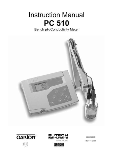
Instruction Manual<strong>PC</strong> <strong>510</strong>Bench pH/Conductivity Meter68X090816Technology Made Easy ...Rev. 3 12/03
PrefaceThank you for choosing the <strong>PC</strong> <strong>510</strong> pH and Conductivity bench meter series.This manual serves to explain the use of the <strong>PC</strong> <strong>510</strong> bench meter. The manual functions as a step-bystepoperational guide to help you familiarise with the meter’s features and as a handy referenceguide.This instruction manual is written to cover as many anticipated applications and uses of the <strong>PC</strong> <strong>510</strong>bench meter as possible. If there are doubts in the use of the meter, please do not hesitate to contactthe nearest Authorised Distributors.Eutech <strong>Instruments</strong>/ <strong>Oakton</strong> <strong>Instruments</strong> cannot accept any responsibility for damage or malfunctionto the meter caused by improper use of the instrument.The information presented in this manual is subject to change without notice as improvements aremade, and does not represent a commitment on the part of Eutech <strong>Instruments</strong> Pte Ltd/ <strong>Oakton</strong><strong>Instruments</strong>.Note: Eutech <strong>Instruments</strong> Pte Ltd/ <strong>Oakton</strong> <strong>Instruments</strong> reserves the right to makeimprovements in design, construction, and appearance of our products without notice.Copyright © 2001 All rights reserved.Eutech <strong>Instruments</strong> Pte Ltd<strong>Oakton</strong> <strong>Instruments</strong>Rev. 3 12/03
TABLE OF CONTENTS1 INTRODUCTION 12 METER INFORMATION 12.1 Meter parts 12.2 Customised LCD 12.3 Slide-out card 12.4 Rear instrument panel 12.5 AC/DC adapter 22.6 Electrodes 22.7 Electrode holder 23 KEYPAD FUNCTIONS 23.1 Keypad 23.2 Display 44 PREPARATION 54.1 Connecting the Sensor Electrode 54.1.1 To connect the pH electrode: 54.1.2 To connect the conductivity/temperature probe: 54.2 Connecting the A.C. Adapter 55 CALIBRATION 65.1 Important information on meter calibration 65.2 Preparing the meter for calibration 65.3 pH calibration 75.3.1 Preparing for pH calibration 75.3.2 Before starting 75.3.3 To calibrate pH 75.4 Conductivity/TDS calibration 95.4.1 Preparing for conductivity/TDS calibration 95.5 TDS Calibration 115.5.1 Calibrating for TDS directly 115.6 Calibration with Conductivity Standard and TDS factor 115.6 Calibration with Conductivity Standard and TDS factor 125.7 Temperature Calibration 136 MEASUREMENT 146.1 Taking pH Measurements 146.1.1 Automatic Temperature Compensation 146.1.2 Manual Temperature Compensation (pH) 146.1.3 Taking pH Measurements 156.2 Taking Conductivity or TDS Measurement 156.2.1 Automatic Temperature Compensation 156.2.2 Manual Temperature Compensation 166.2.3 Setting a manual temperature compensation value 176.2.4 Taking Measurements (Conductivity or TDS) 176.2.5 Using Auto and Manual Ranging Function (for conductivity & TDS) 187 HOLD FUNCTION 208 ADVANCED SETUP FUNCTIONS 208.1 Advanced SETUP mode Overview 228.2 P1.0: Viewing previous pH calibration data 258.3 P2.0: Viewing pH electrode data 268.4 P3.0: pH Measurement configuration 278.4.1 P3.1: READY Indicator and auto endpoint function 288.4.2 P3.2: Selecting number of pH calibration points 298.4.3 P3.3 Selecting USA or NIST buffer 298.4.4 P3.4 Selecting °C or °F 308.5 P4.0: Resetting to factory default settings (pH) 318.6 P5.0: Viewing previous conductivity calibration data 328.7 P6.0: Viewing conductivity probe data 338.8 P7.0: Conductivity or TDS measurement configuration 348.8.1 P7.1: READY indicator and auto endpoint function 348.8.2 P7.2: Selecting °C or °F 358.8.3 P7.3: Selecting Automatic or Manual Temperature Compensation 358.8.4 P7.4: Setting the TDS factor 368.9 P8.0: Temperature 378.9.1 P8.1: Selecting the temperature coefficient 378.9.2 P8.2: Adjusting the normalisation temperature 388.9.3 P9.0: Resetting to factory default settings (conductivity) 38
9 PROBE CARE AND MAINTENANCE 399.1 pH Electrode care 399.2 Conductivity electrode 4010 TROUBLE SHOOTING GUIDE 4111 ERROR MESSAGES 4212 SPECIFICATIONS 4313 ACCESSORIES 4414 ADDENDUM 2: CALCULATING TDS CONVERSION FACTORS 4815 ADDENDUM 3: STANDARD pH BUFFERS 4816 ADDENDUM 4: CALCULATING TEMPERATURE COEFFICIENTS 4917 ADDENDUM 5: METER FACTORY DEFAULT SETTINGS 5018 WARRANTY 5119 RETURN OF ITEMS 51
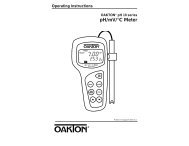
Instruction Manual <strong>PC</strong> <strong>510</strong>1 INTRODUCTIONThank you for selecting the <strong>PC</strong> <strong>510</strong> pH and Conductivity bench meter. This step-by-step instructionmanual gives you a detailed description on the use and operation of features on the meter. This <strong>PC</strong><strong>510</strong> pH and Conductivity bench meter is designed to be user-friendly while providing unprecedentedlevels of accuracy, repeatability and reliability.The <strong>PC</strong> <strong>510</strong> is an advanced microprocessor-based (ASIC - Application Specific Integrated Circuit)ideal for routine measurement that best meets discerning user’s individual needs. This multi-parametermeter reads pH, mV, Conductivity, Total Dissolved Solids (TDS) and temperature (°C or °F). It hassplash-proof keypad, simultaneous pH/mV/Conductivity/TDS and temperature display on a largeangled custom LCD. This instruction manual is illustrated with useful hints and diagrams that showwhich specific key-presses to access for each function.2 METER INFORMATIONThe <strong>PC</strong> <strong>510</strong> meter is packaged in a corrugated box that is made of environment-friendly materials andcan be re-cycled.2.1 Meter partsThe instrument is designed to give an aesthetic look as well as ergonomic functionality. A largecustom dual LCD is provided at an angle for optimum viewing. A splash-proof keypad with audibletactile response gives you a good feel of the instrument. A slide-out instruction card offers a handyreference. Listed below are the major components of the meter.2.2 Customised LCDThe <strong>PC</strong> <strong>510</strong> bench meter is characterised by large dual custom LCD (Liquid Crystal Display). Thedisplay has also mode annunciators for pH, temperature, mV, conductivity and TDS readings. Thesecondary (lower) display shows the temperature readings simultaneously with the primary (upper)display of measured mode. Special annunciators such as graphical symbols, error messages,measurement units and modes of operation are arranged around the primary and secondary displaysto give a comprehensive display. The integration of graphics and error messages into the LCDprovides you a higher level of user-friendliness and easy readability.2.3 Slide-out cardA plastic slide-out card is provided at the bottom of the <strong>PC</strong> <strong>510</strong> bench meter. The function of this cardis to provide a quick guide to the functions of the individual keys as well as to provide a usefultroubleshooting reference.2.4 Rear instrument panelThe <strong>PC</strong> <strong>510</strong> bench meter provides three connectors at the rear of the meters. These connectors arelabeled CON/TEMP, pH and DC.CON/TEMP pH DCFigure 1 : View of meter rear panel1
Instruction Manual <strong>PC</strong> <strong>510</strong>ConnectorCON/TEMPpHDCFunctionFor connecting 6-pins conductivity/TDS sensor with built-in temperature sensor to themeter or optional temperature probe for use with pH electrode (when applicable).Always make sure that the connector is clean and dry.For connecting pH sensor with a BNC connector to the meter. Always make sure thatthe connector is clean and dry.For connection to the AC power source to the power jack (DC).2.5 AC/DC adapterThe AC/DC adapter converts the power mains voltage 120/220 VAC to low DC voltage for the <strong>PC</strong> <strong>510</strong>bench meter operation. Two basic models of adapters are available depending upon power supplyspecification of each country.2.6 ElectrodesDescription Order Code VoltageAC Adapter 120 V EC-120-ADA / 35615-07 110-120 V, 50-60 HzAC Adapter 220 V EC-220-ADA / 35615-08 220-240 V, 50-60 HzYour meter includes two probes:• pH electrode with BNC connector• conductivity probe with built-in temperature sensor with a notched 6-pin connectorThe temperature sensor built into the conductivity probe will also compensate for pH readings as longas both probes are in your solution at the same time.If you want to use a “3-in-1” pH probe with a built-in temperature sensor, or if you want to use aseparate temperature probe, you will need to disconnect the conductivity probe to allow for connectionof the separate temperature sensor.2.7 Electrode holderThe integral electrode holder serves as a handy holder for mountingthe pH and conductivity/temperature probes during measurement orwhen idle.The bench meter’s base plate has a side metal bar to which youcan attach an integral swivel electrode holder. You can mount theelectrode holder on either right or left side of the meter.To position the electrode arm:Use a Philips screwdriver to remove the screw holding theelectrode holder. Slide the side metal bar until the second screwholder.slot lines up with the original screw hole. Use the screw removedearlier to secure the electrode holder into position. Note the side3 KEYPAD FUNCTIONSmetal bar is reversible. If desired, remove screw holding electrodeholder base and slide out of brackets. Slide base into brackets onopposite side and tighten screws. See Figure 2.3.1 KeypadTheTo install<strong>PC</strong> <strong>510</strong>electrodeis equippedarm towiththelargemeter:tactile response keypad foreaseTo mountof use.theAllelectrodekeys havearmprimaryinto thefunctionmetalwithrodsomeon thekeyssidehavingbar,secondaryalign the slotfunctions.with the metal rod and base of electrode arm. Pushit downwards until it fully sits into position. Avoid using excessiveforce when fixing or removing. The electrode arm is ready for use.NOTE: Move the base of electrode holder if you wish to swing theelectrode holder about. To prevent the meter form toppling overcausing accidental spills, DO NOT swing the body of theelectrode holder.Figure 2: To position electrode armBody of ElectrodeHolderSide Metal BarFigure 3: Installing theelectrode armBase ofElectrodeHolder2
Instruction Manual <strong>PC</strong> <strong>510</strong>HOLDON/OFFMODEENTERRANGESETCALMEASFigure 4: KeypadON/OFFSETMODEHOLDPowers the meter on or off. When meter is switched on, it starts in the mode the meterwas last in when powered off.Enters advanced setup mode. SETUP mode lets you customise meter preferences anddefaults, and view calibration and probe data.Measurement: Press MODE to toggle between pH, mV, conductivity and TDS.Calibration: In calibration mode, press MODE to access temperature calibration.Freezes the measured reading. To activate, press HOLD while in measurement mode. Torelease, press HOLD again.Note: When auto endpoint feature is switched on, meter automatically holds reading after5 seconds of stability. The HOLD indicator appears on the display. Press HOLD to releaseauto endpoint feature.Toggles between Calibration and Measurement mode. Example: If you are in pHmeasurement mode, press CAL/MEAS to enter pH calibration mode.CAL/MEASNote: Temperature calibration is available from pH, TDS or Conductivity calibration mode.In Setup mode: Press CAL/MEAS to return to main menu from sub menus. PressCAL/MEAS again to return to measurement mode from main menu.ENTER/RANGEENTER: Press to confirm values in Calibration mode and to confirm selections in Setupmode.RANGE: Press to switch to manual ranging in Conductivity or TDS mode.Press in Setup mode to scroll up through subgroups. Also lets you increase the valuesin the conductivity, TDS and temperature calibration modes.Press in Setup mode to scroll down through subgroups. Also lets you decrease thevalues in the conductivity, TDS and temperature calibration modes.3
Instruction Manual <strong>PC</strong> <strong>510</strong>3.2 DisplayThe <strong>PC</strong> <strong>510</strong> features a large dual display that shows the measured parameter in the primary display,plus temperature in °C or °F in the secondary display. It also features mode annunciators that describethe meter’s functions.Primary Display1 2 3SETUP MEAS CALmV%pH20 READYmS19µSHOLDK =pptONppm181617OFF-8.8.8.8ERR-1.8.8.8°C °FpHATC4567891011121514Secondary DisplayFigure 5: Full LCD Screen131. SETUP mode indicator2. MEASurement mode indicator3. CALibration indicator4. mV indicator5. % indicator6. pH measurement indicator7. milli-Siemens indicator8. micro-Siemens indicator9. parts per thousand indicator10. parts per million indicator11. temperature indicator12. pH indicator13. Automatic TemperatureCompensation (ATC) indicator14. ERRor indicator15. probe indicator16. calibration solution indicator17. cell constant indicator18. ON/OFF indicator19. HOLD indicator20. READY indicator4
Instruction Manual <strong>PC</strong> <strong>510</strong>4 PREPARATION4.1 Connecting the Sensor Electrode4.1.1 To connect the pH electrode:1. Slide the BNC connector of the probe over the BNC connector socket on the meter. Make sure theslots of the connector are in line with the posts of the socket. Rotate and push the connectorclockwise until it locks.2. To remove electrode, push and rotate the connector anti-clockwise. While holding onto the metalpart of connector, pull it away from the meterNOTE: Keep connector dry and clean. Do not touch connector with soiled hands.CAUTION: Do not pull the probe cord or the probe wires might disconnect.4.1.2 To connect the conductivity/temperature probe:1. Line up the notch and 6-pins on the probe connector with the holes in the connector located on thetop of the meter. Push down and screw the metal sleeve to lock the probe connector into place.See Figure 1 on page 1 for the meter rear panel view.2. To remove probe, unscrew the metal sleeve and slide up the probe connector. While holding ontothe metal sleeve, pull probe away from the meter.NOTE: Follow the same directions to connect an optional separate temperature element.Keep connector dry and clean. Do not touch connector with soiled hands.CAUTION: Do not pull on the probe cord or the probe wires might disconnect.4.2 Connecting the A.C. Adapter1. Before plugging in the A.C. adapter, switch off the meter and the power source of the A.C.adapter. This is a safety precaution that should be adhered to safeguard your meter.2. The A.C. adapter should have the following settings:Output voltage: 9 V D.C.Current: 500 mANOTE: Ensure that the input mains voltage (110/220/240 V) matches your adapter requirements.3. Insert the D.C. jack into the socket at rear panel of the meter as shown in Figure 1on page 1.4. Switch on the power to the adapter, followed by the meter.5
Instruction Manual <strong>PC</strong> <strong>510</strong>5 CALIBRATION5.1 Important information on meter calibrationWhen you calibrate your meter, old calibration points are replaced on a “point by point” basis in pH,and on a “range by range” basis in conductivity or TDS.For example:• pH: if you previously calibrated your meter at pH 4.01, 7.00 and 10.01, and you recalibrate at pH7.00, the meter retains the old calibration data at pH 4.01 and pH 10.01.• Conductivity: if you previously calibrated your meter at 1413 µS in the 0 to 1999 µS range andyou recalibrate at 1500 µS (which is also in the 0 to 1999µS range), the meter will replace the oldcalibration data (1413 µS) in that range. The meter will retain all calibration data in other ranges.• TDS: If you previously calibrated your conductivity meter at 300 ppm in the 0 to 999 ppm rangeand you re-calibrate at 500 ppm (which is also in the 0 to 999 ppm), the meter will replace the oldcalibration data (300 ppm) in that range. The meter will retain all calibration data in other ranges.To view current calibration points:• pH: Program P1.0 in the SETUP section 8.2 page 38.• Conductivity & TDS: Program P5.0 in the SETUP section, page 32.To completely recalibrate your meter, or when you use a replacement probe, it is best to clear oldcalibration data by resetting the meter.To reset the meter to its factory defaults:• pH: Program P4.0 in the SETUP section, page 32.• Conductivity & TDS: Program P9.0 in the SETUP section, page 38.NOTE: Resetting the meter will set meter to factory defaults. Conductivity and pH must be resetseparately.For directions on how to calibrate your meter:• See section 5.3 on page 7 for pH calibration• See section 5.4 on pages 9 for conductivity calibration• See section 5.5 on page 11 for TDS calibration5.2 Preparing the meter for calibrationBefore starting calibration, make sure you are in the correct measurement mode. When you switch onthe meter, the meter starts up in the measurement mode you shut it off in. For example, if you shut themeter off in pH measurement mode, the meter will be in the pH measurement mode when you switchthe meter on.Do not re-use calibration solutions after calibration. Contaminants in the solution can affect thecalibration, and eventually the accuracy of the measurements. See section 13 on “Accessories” onpage 44 for information on our high quality calibration solutions.6
Instruction Manual <strong>PC</strong> <strong>510</strong>5.3 pH calibrationNOTE: We recommend that you perform at least a 2-point calibration using standard buffers thatbracket (one above and one below) the expected sample range.5.3.1 Preparing for pH calibrationThis meter is capable of up to 5-point pH calibration to ensure accuracy across the entire pH range ofthe meter. Select from the following buffer options:• USA: pH 1.68, 4.01, 7.00, 10.01 and 12.45• NIST: pH 1.68, 4.01, 6.86, 9.18 and 12.45The meter automatically recognises and calibrates to these standard buffer values, which makes pHcalibration faster and easier.NOTE: Selection of USA or NIST buffer standards must be done prior to calibration. Refer to Section8.4 on P3.3 on page 29.5.3.2 Before startingBe sure to remove the protective electrode storage bottle or rubber capof the probe before calibration or measurement. If the electrode hasbeen stored dry, hydrate the probe in tap water for 10 minutes beforecalibrating or taking readings to saturate the pH electrode surface andminimise drift.Wash your probe in de-ionised water after use, and store in electrodestorage solution. If storage solution is not available, use pH 4.01 or7.00 buffer for short term storage. DO NOT store electrode in distilledor de-ionised water.5.3.3 To calibrate pH1. If necessary, press the MODE key to select pH mode. The pHindicator appears in the upper right hand corner of the display.2. Rinse the probe thoroughly with de-ionised water or rinse solution.Do not wipe the probe as this causes a build-up of electrostaticcharge on the glass surface.CALMEASMEAS7.1622.3CAL7.167.00pH°CATCpHpH3. Dip the probe into the standard calibration buffer. The end of theprobe must be completely immersed into the sample. Stir the probegently to create a homogeneous sample.NOTE: The temperature element is in the conductivity cell. Fortemperature compensated readings, dip the conductivity cell or ATCprobe into the calibration buffer as well.4. Press CAL/MEAS to enter pH calibration mode. The CAL indicatorwill be shown. The primary display will show the measured readingwhile the smaller secondary display will indicate the pH standardbuffer solution.5. Wait for the measured pH value to stabilise. If the READY indicatorhas been activated through the Setup, the READY appears whenthe reading is stable.6. Press ENTER to confirm calibration. The meter is now calibrated tothe current buffer. The lower display automatically scrolls throughthe remaining buffer options.• If you are performing multi-point calibration, go to step 7.READYENTERRANGEREADYCAL7.167.00CAL7.007.00Figure 6: pH calibrationpHpHpHpH7
Instruction Manual <strong>PC</strong> <strong>510</strong>• If you are performing one-point calibration, go to step 9.7. Rinse the electrode with de-ionised water or rinse solution, andplace it in the next pH buffer.8. Follow steps 5 to 7 for additional calibration points.9. When calibration is complete, press CAL/MEAS to return to pHmeasurement mode.READYENTERRANGECAL4.154.01pHpHNOTE: To exit from pH calibration mode without confirming calibration,DO NOT press ENTER in step 6. Press CAL/MEAS instead.If the selected buffer value is not within ±1.0 pH from the measured pHvalue: the electrode and buffer icon blink and the ERR annunciatorappears in the lower left corner of the display.To limit the number of pH buffer values available during calibration,see section 8.4 Setup P3.2 on page 29.READYCAL4.014.01pHpHFigure 7: Next point calibrationfor pH 4.01CAL0.64ERR1.68pHpHFigure 8: Err message andelectrode icon will appear ifincorrect buffer is used8
Instruction Manual <strong>PC</strong> <strong>510</strong>5.4 Conductivity/TDS calibrationThe <strong>PC</strong> <strong>510</strong> has 5 measuring ranges. You can calibrate 1 point each of the measuring ranges (up to 5points). If you are measuring values in more than 1 range, make sure to calibrate each of the rangesyou are measuring. All new calibration data will over-ride existing stored calibration data for eachmeasuring range you calibrate.• If you are measuring in ranges near to or greater than 20 mS (10 ppt), or near to or lower than 100µS (50 ppm), calibrate the meter at least once a week to get specified ±1% Full Scale accuracy.• If you are measuring in the mid-ranges and you washed the probe in de-ionised water and storedit dry, calibrate the meter at least once a month.• If you take measurements at extreme temperatures, calibrate the meter at least once a week.5.4.1 Preparing for conductivity/TDS calibrationFor best results, select a standard value close to the sample value you are measuring. Alternatively,use a calibration solution value that is approximately 2/3 the Full-Scale value of the measurementrange you plan to use. For example, in the 0 to 1999 µS conductivity range, a 1413 µS solution is agood solution for calibration.See the table below for recommended calibration solution ranges.RangeIndicatorConductivityRangeRecommended CalibrationSolution RangeTDS RangeRecommended CalibrationSolution Ranger 1 0.00 to 19.99 µS 6.00 to 17.00 µS 0.00 to 9.99 ppm 3.00 to 8.50 ppmr 2 0.0 to 199.9 µS 60.0 to 170.0 µS 10.0 99.9 ppm 30.0 to 85.0 ppmr 3 0 to 1999 µS 600 to 1700 µS 100 to 999 ppm 300 to 850 ppmr 4 0.00 to 19.99 mS 6.00 to 17.00 mS 1.00 to 9.99 ppt 3.00 to 8.50 pptr 5 0.0 to 199.9 mS 60.0 to 170.0 mS 10.0 to 200 ppt 30.0 to 170.0 pptCalibration Solution RangesTemperature Coefficient: These meters are factory set to a temperature coefficient of 2.1 % per °C.For most applications this will provide good results. See Program P8.1 on page 37 to set thetemperature coefficient to different value. See Addendum 2, “Calculating Temperature Coefficients” todetermine the appropriate temperature coefficient for your solution.Normalisation Temperature: The factory default value for normalisation temperature is 25 °C. If youneed to normalise to a value other than 25 °C, see Program P8.2 on page 38.Do not reuse calibration solutions after calibration. Contaminants in the solution can affect thecalibration, and eventually the accuracy of the measurements. Use fresh calibration solution each timeyou calibrate your meter.All new calibration data will over-ride existing stored calibration data for each measuring rangecalibrated.9
Instruction Manual <strong>PC</strong> <strong>510</strong>Calibrating for Conductivity:1. If necessary, press the MODE key to select conductivity mode.2. Rinse the probe thoroughly with de-ionised water or a rinsesolution, then rinse with a small amount of calibration standard.3. If necessary, ensure that the probe’s yellow probe guard isattached. Dip the probe into the calibration standard. Immerse theprobe tip beyond the upper steel band. Stir the probe gently tocreate a homogeneous sample.4. Wait for the measured conductivity value to stabilise. If the READYindicator has been activated (SETUP program P7.1 – see page31), the READY annunciator lights when the reading is stable.5. Press CAL/MEAS to enter conductivity or TDS calibration mode.The CAL indicator will appear in the upper right corner of thedisplay.CALMEASMEAS140922.3CAL140922.3µS°CATCµS°CATC6. Press the or key to change the value on the primary displayto match the value of the calibration standard.7. Press ENTER to confirm calibration value. The meter returns to theMEAS (measurement) mode.8. Repeat steps 1 to 7 for other measuring ranges.READYCAL14131409µSNOTES: When entering calibration mode, the meter will display thefactory default value. If the meter was previously calibrated, the displaymay “jump” to the factory default / uncalibrated value when switchingfrom measurement to calibration mode.To exit from Conductivity calibration mode confirming calibration,DO NOT press the ENTER key in step 7. Press CAL/MEAS instead.This will retain the meter’s old calibration data in the measuring rangeof the calibration.ENTERRANGEREADYMEASµS141322.3°CATCYou can offset the conductivity reading up to ±40% from defaultsetting. If your measured value differs by more than ±40% clean orreplace probe as needed, or use a calibration standard with a highervalue as required.Figure 9: ConductivitycalibrationA wide selection of high-quality calibration standards is available. See page 44 for more information.10
Instruction Manual <strong>PC</strong> <strong>510</strong>5.5 TDS Calibration5.5.1 Calibrating for TDS directlyThe factory default setting for TDS conversion factor is 0.5. If yoursolution has a different TDS factor, you can improve calibrationaccuracy by setting the TDS factor prior to calibration. See ProgramP7.4 on page 36 for directions.1. If necessary, press the MODE key to select TDS mode.2. Rinse the probe thoroughly with de-ionised water or a rinsesolution, then rinse with a small amount of calibration standard.3. If necessary, ensure that the probe’s yellow probe guard isattached. Dip the probe into the calibration standard. Immerse theprobe tip beyond the upper steel band. Stir the probe gently tocreate a homogeneous sample. Allow time for the reading tostabilise.4. Press the CAL/MEAS to enter TDS calibration mode. The CALindicator will appear in the upper right corner of the display.5. Press the or key to change the value on the primary displayto match the value of the calibration standard.6. Press ENTER to confirm the calibration value. The meter returnsto the MEAS (measurement) mode. See Figure 10.7. Repeat steps 1 to 6 for other measuring ranges.CALMEASREADYENTERRANGEMEAS265 ppm25.8°CATCCAL265 ppm25.8°CATCCAL300 ppm265NOTES:To exit from TDS Calibration mode without confirming calibration, DONOT press ENTER key in step 6. Press CAL/MEAS instead. This willretain the meter’s old calibration data in the measuring range of thecalibration. You can offset the TDS reading up to ±40% from thedefault setting. If your measured value differs by more than ±40%,clean or replace probe as needed, or use a calibration standard with ahigher value as required.MEASREADY300 ppm25.8°CATCFigure 10: TDS calibration11
Instruction Manual <strong>PC</strong> <strong>510</strong>5.6 Calibration with Conductivity Standard and TDS factorThe concentration of salts dissolved in solution increases the conductivity of that solution. Thisrelationship varies from salt to salt and is roughly linear over a given range for a given salt.The TDS conversion factor is the number used by the meter to convert from conductivity to TDS.Instead of calibrating for TDS directly (described above), you can calibrate the <strong>PC</strong> <strong>510</strong> bench meterby:1. Calibrating to conductivity standards (as described above) and then2. Entering the appropriate TDS conversion factor into the meter.To determine the conductivity to TDS conversion factor for your solution:• Addendum 1 on page 47 lists some commonly used conversion factors.• Addendum 2 on page 48 describes how to calculate the TDS conversion factor for othersolutions.Enter the TDS conversion factor into your meter as described under Section 8.8, in Program P7.4,Setting the TDS Factor on page 36.12
Instruction Manual <strong>PC</strong> <strong>510</strong>5.7 Temperature CalibrationThe conductivity electrode (EC-CONSEN91W / 35608-50) supplied has abuilt-in temperature sensor. Alternatively, a separate temperature sensingelement can be used (such as temperature probe EC-WPPHTEM-01W /35618-05), or a “3-in-1” pH/Temperature combination electrode with ATCconnection.The conductivity probe is factory calibrated. Temperature calibration isrecommended only if you suspect temperature errors may have occurredover a long period of time, or if you have a replacement probe.Temperature calibration is accessible during pH, conductivity or TDScalibration.CALMEASMEAS7.1622.3CAL7.167.00pH°CATCpHpHTemperature Calibration1. Make sure the conductivity electrode, or temperature probe, or “3-in-1”electrode is attached to the 6-pin connector.2. Switch the meter on.3. Press the CAL/MEAS key to enter calibration mode (either from pH orconductivity mode). The CAL indicator will appear above the primarydisplay.4. While in pH (or conductivity or TDS) calibration mode, press the MODEkey to enter temperature calibration mode. The primary display showsthe last set temperature value and the secondary display shows thetemperature reading with zero offset.5. Dip the ATC probe into a solution of known temperature (i.e. atemperature bath). Allow time for the temperature probe to stabilise.MODEENTERRANGECAL22.322.3CAL22.022.3°CATC°CATC6. Scroll with the or key to set the correct temperature value (i.e. thetemperature of the temperature bath). You can adjust the reading by 0.1°C or °F increments.7. Once you have selected the correct temperature press the ENTER key.The meter automatically returns to measurement mode.NOTES:• You can offset the temperature reading up to ±5° from default reading.Figure 12: Temperature calibrationin pH mode• To exit this program without confirming the temperature calibration value, DO NOT press ENTER,press CAL/MEAS in step 7 instead.READYMEAS7.1622.0pH°CATC13
Instruction Manual <strong>PC</strong> <strong>510</strong>6 MEASUREMENT6.1 Taking pH Measurements6.1.1 Automatic Temperature CompensationAutomatic Temperature Compensation only occurs when a temperature sensing element is pluggedinto the meter.Temperature sensing element refers to the following probes made specifically for this meter. Seeaccessories for ordering information• The conductivity electrode with a built-in temperaturesensorREADYMEAS• Temperature probe; or• The 3-in-1 pH/Temperature combination electrode.If there is no temperature sensor plugged into the meter, the defaultmanual temperature setting is automatically 25 °C. You can manuallyset the temperature to match your working conditions using a separatethermometer.7.05°CpH24.5ATCFigure 13: ATC annunciator willlight up when connected totemperature probeFor automatic temperature compensation (ATC) simply plug the temperature probe into the meter (seepage 5 for directions). The ATC indicator will light up on the LCD. See Figure 13.NOTE: The temperature sensing element must be submersed in the liquid you are measuring.6.1.2 Manual Temperature Compensation (pH)IMPORTANT: For manual compensation, you must disconnect thetemperature probe (see page 5 for instructions).1. Switch the meter on. Press MODE key to select pH mode.2. Press the CAL/MEAS key to enter pH calibration mode. The CALindicator will appear above the primary display.3. While in pH calibration mode, press the MODE key to entertemperature calibration mode. The primary and secondary displaysshow the last set temperature value.4. Check the temperature of your sample using an accuratethermometer.5. Press the or key to set the temperature to the measuredvalue from step 4.6. Press ENTER to confirm the selected temperature and to return tothe pH measurement mode.ENTERRANGECAL25.025.0CAL30.025.0°C°CSee Figure 14.The meter will now compensate pH readings for the manually settemperature.NOTES: To exit this program without confirming the manualtemperature compensation value, DO NOT press ENTER in step 6.Press CAL/MEAS instead.READYMEAS7.0530.0pHFigure 14: Manual temperaturecompensation°C14
Instruction Manual <strong>PC</strong> <strong>510</strong>6.1.3 Taking pH MeasurementsBe sure to remove the electrode storage bottle or protective rubber capon the electrode before measurement.To take readings:1. Rinse the pH electrode with de-ionised or distilled water before useto remove any impurities adhering to the probe body. If the pHelectrode has dehydrated, soak it for 30 minutes in electrodestorage solution or 2M – 4 M KCL solution (sold separately).MEAS8.2321.3pH°CATCFigure 15: Measurement mode2. Press ON to switch meter on.3. Press the MODE key to select pH measurement mode. The MEAS annunciator appears on thetop center of the LCD. The ATC indicator appears in the lower right-hand corner to indicateAutomatic Temperature Compensation.NOTE: For pH manual temperature compensation, you must disconnect the conductivity cell from the6-pin connector. The ATC indicator will disappear form the display. You also need to set a manualtemperature compensation value. See Section 6.2.2: Manual Temperature Compensation on page 16.4. Dip the probe into the sample. Since the conductivity cell contains the temperature sensor, makesure it is also immersed in your solution.When dipping the probe into the sample, the sensor or the glass bulb of the electrode must becompletely immersed into the sample. Stir the probe gently in the sample to create a homogeneoussample.5. Allow time for the reading to stabilise. Note the reading on the display. If the READY indicator isselected on, it will appear when the reading is stable. See below for more information.Taking measurements with READY indicator selected onIf the READY indicator has been activated, the READY annunciator lights when the reading is stable *.Switch the READY indicator on or off in SETUP program P3.1. See page 28 for directions.* The READY indicator appears and the reading holds until the measured value exceeds the tolerance(±0.02 pH; +0.8 mV < 400; ±1.2 mV > 400). Then READY annunciator turns off.Taking measurements with the auto endpoint feature selected onWhen a reading is stable for more than 5 seconds, the auto endpoint feature will automatically “HOLD”the reading. The “HOLD” indicator appears on the left side of the display. Press the HOLD key torelease the reading. Switch the Auto endpoint feature on or off in SETUP program P3.1, see page 28for instructions.6.2 Taking Conductivity or TDS Measurement6.2.1 Automatic Temperature CompensationFor automatic temperature compensation (ATC), simply plug theconductivity probe into the meter (see page 5 for directions). The ATCindicator will light on the LCD.NOTE: If the ATC indicator does not light, manual temperaturecompensation may be selected in the meter’s SETUP mode. SeeProgram P7.3 on page 35 for directions on selecting AutomaticTemperature Compensation.MEASREADY140224.5µSATCFigure 16: ATC annunciator willlight up when connected totemperature probe°C15
Instruction Manual <strong>PC</strong> <strong>510</strong>6.2.2 Manual Temperature CompensationIMPORTANT: For manual compensation, you must deactivate thetemperature probe.Selecting Manual Temperature Compensation for conductivitySelecting between Automatic Temperature Compensation (ATC) andManual Temperature Compensation in the SETUP program P7.3 onpage 35. Meter default is ATC on.From Conductivity or TDS measurement mode1. Press SETUP key to enter Setup mode.2. Press the or key to scroll through subgroups until you viewparameter P7.0. See Figure 17.3. Press ENTER key three times to select parameter 7.3. The upperdisplay shows “ATC” and the lower display shows “P7.3”.SETUPFigure 17: P7.0 configurationsetup for conductivity & TDSENTERRANGESETU<strong>PC</strong>OFP 7.0mSµ Spptppm4. Press ENTER key again. The upper display shows “ATC” and thelower display shows “YES” or “NO”.5. Press the or key to select the Automatic TemperatureCompensation feature on (ATC) or off (ATC off). See Figure 14.6. Press ENTER key to confirm selection and to return to thesubgroup menu. Press the CAL/MEAS key to return tomeasurement mode.Note that the ATC indicator no longer appears on the display.Proceed to the next section to select a manual temperaturecompensation value.ENTERRANGESETUPp 7.3 °C ATCYES °C ATCSETUP°CFigure 18: Turning ATCfeature ON or OFF16
Instruction Manual <strong>PC</strong> <strong>510</strong>6.2.3 Setting a manual temperature compensation valueTo use manual temperature compensation, you need to enter the temperature value of your processinto the meter. This is the value at which reading will manually temperature compensate. You canselect any temperature between 0 and 100 °C (32 to 212 °F). Default value is 25 °C (77 °F).To select a manual temperature compensation value1. Switch the meter on. Press the MODE key to select conductivity orTDS measurement mode.2. If necessary, select ATC off as described in P7.3 on page 35. TheATC indicator will not appear on the display.3. Press the CAL/MEAS key to enter conductivity or TDS calibrationmode. The CAL indicator will appear above the primary display.4. While in conductivity (or TDS) calibration mode, press the MODEkey to enter temperature calibration mode. The primary andsecondary displays show the last set temperature value.5. Check the temperature of your sample using an accuratethermometer.6. Press the or key to offset the temperature to the measuredvalue from step 5.7. Press ENTER to confirm the selected temperature and to return tothe conductivity measurement mode. See Figure 18.The meter will now compensate conductivity or TDS readings formanually set temperature.NOTES: To exit this program without confirming the manualtemperature compensation value, DO NOT press ENTER in step 7.Press CAL/MEAS instead.Setting the manual temperature compensation value for conductivitywill change the manual temperature compensation value for pH to thesame value, and vice versa.ENTERRANGEREADYCAL25.025.0CAL30.025.0MEAS256°C30.0Figure 19: Manual TemperatureCompensation°C°C6.2.4 Taking Measurements (Conductivity or TDS)To take readings:1. Rinse the probe with de-ionised or distilled water before use toremove any impurities adhering to the probe body. Shake or airdry. To avoid contamination or dilution of your sample, rinse probewith a small volume of your sample liquid.2. Press ON to switch meter on.MEASREADY34521.3µS°CATC3. Press the MODE key to select conductivity or TDS measurementmode. The MEAS annunciator appears on the top center of theLCD. The ATC indicator appears in the lower right hand corner toindicate Automatic Temperature Compensation.Figure 20: During measurementNOTE: For conductivity manual temperature compensation, you must de-activate the temperaturesensor built into the conductivity probe and set a manual temperature compensation. See page 14 formore information. The ATC indicator will disappear from the display.17
Instruction Manual <strong>PC</strong> <strong>510</strong>4. If necessary, ensure that the probe’s yellow probe guard is attached. Dip the probe into thesample. When dipping the probe into the sample, take care to ensure that the liquid level is aboveits upper steel band. Stir the probe gently in the sample to create a homogeneous sample.5. Allow time for the reading to stabilise. Note the reading on the display. If the READY indicator isselected on, it will appear when the reading is stable. See Program P7.1 on page 34 for moreinformation.6. Press the MODE key to toggle between conductivity, TDS and pH readings.NOTE: You can use the Conductivity Manual Ranging function to manually select a specific range inwhich your readings will appear. See page 19 for directions.Taking measurements with READY indicator onIf the READY indicator has been activated, the READY annunciator lights when the reading is stable *.Switch the READY indicator on or off in SETUP program P7.1. See page 34 for directions.Taking measurements with the auto endpoint feature selected onWhen a reading is stable for more than 5 seconds, the auto endpoint feature will automatically “HOLD”the reading. The “HOLD” indicator appears on the left side of the display. Press the HOLD key torelease the reading. Switch the Auto endpoint features on or off in SETUP program P7.1, see page 34for instructions.6.2.5 Using Auto and Manual Ranging Function (for conductivity& TDS)Auto-rangingYour meter automatically selects the range in which your readingsappear. For example:MEAS199.9µS°CATC1. Dip the conductivity probe into a standard solution, say, 12.88 mS.2. It will automatically select the most appropriate range, r 4, which is0.00 to 19.99 mS.3. The secondary display on the LCD will momentarily display r 4before it switches to measured temperature value.4. The primary display will show the actual conductivity value. SeeFigure 20.MEAS1999µS°CATCMEAS19.99mS°CATCMEAS12.8825.5mS°CATCFigure 21: Auto-ranging feature18
Instruction Manual <strong>PC</strong> <strong>510</strong>Manual-rangingThe manual ranging function lets you select the specific range you want to work in. Refer to page 9 forthe table of range.1. To select the desired measuring range manually, press the RANGEkey while in measurement mode. The meter will lock on to theappropriate range and the “MEAS” indicator blinks.2. Press RANGE key again (if needed) until desired range is selected.3. To re-select the Auto-ranging function, repeatedly press the RANGEkey until the “MEAS” indicator appears without blinking.MEASµSREADY1413ENTERRANGE22.3°CATCMEAS1999µS°CATCREADYMEAS141322.3°CµSATCFigure 22: Manual rangingNOTES:The meter will not let you manually select a range in which the reading will be over-range.The meter resets to the Auto-ranging function once it is turned off. You will have to reset the manualranging function each time you turn the meter off.19
Instruction Manual <strong>PC</strong> <strong>510</strong>7 HOLD FUNCTIONThis feature lets you freeze the display for a delayed observation. HOLD can be used any time inMEAS mode.1. To hold a measurement, press the HOLD key while in measurement mode. “HOLD” will appear onthe display.2. To release the held value, press the HOLD key again. Continue to take measurementsMEASREADYHOLD67820.7°CµSATCFigure 23: HOLD functionNOTE:• If the meter is shut off manually, the HOLD value will be lost.• Your meter has an auto endpoint feature. When this feature is switched on, and when areading is stable for more than 5 seconds, the display will automatically “HOLD” thereading. The “HOLD” indicator appears. Press the HOLD key to release the reading. Toswitch on or off the auto endpoint feature, see SETUP Program P3.1 on page 28 for pHand SETUP Program P7.1 on page 34 for conductivity/TDS.8 ADVANCED SETUP FUNCTIONSThe advanced setup mode lets you customise your meter’s preferences and defaults. The <strong>PC</strong> <strong>510</strong>bench meter features different sub-groups that organise setup parameters.The sub-groups are:For pHFor Conductivity & TDSP1.0 View calibration data (CAL) P5.0 View calibration data (CAL)P2.0 View electrode data (ELE) P6.0 View electrode data (ELE)P3.0 Unit Configuration (COF) P7.0 Unit Configuration (COF)P4.0 Reset to factory defaultsettings (rSt)P8.0 Temperature (tPr)P9.0 Reset to factory default settings(rSt)20
Instruction Manual <strong>PC</strong> <strong>510</strong>SETUPSETUPSETU<strong>PC</strong>ALP 1.0pHSETU<strong>PC</strong>ALP 5.0mSµSpptppmSETUPELEP 2.0pHSETUPELEP 6.0mSµSpptppmSETU<strong>PC</strong>OFP 3.0pHSETU<strong>PC</strong>OFP 7.0mSµSpptppmSETUPMEASP 4.0pHSETUPP 8.0mSµSpptppm°C °FSETUPMEASP 9.0mSµSpptppmFigure 24: Overall view of SETUP programs for pH (on left) & conductivity/TDS (on right)21
Instruction Manual <strong>PC</strong> <strong>510</strong>8.1 Advanced SETUP mode Overview1. In either pH or Conductivity measurement mode, press the SETUP key to enter Setup mode.2. Press the or key to scroll through sub-groups.3. Press ENTER key to enter a particular parameter.See Addendum 4 on page 49 for a table of meter factory default settings.SETUP in pH measurement modeSETU<strong>PC</strong>ALP 1.0pHP1.0: View previous calibration dataP1.1 First calibration point (pH 1.68)P1.2 Second calibration point (pH 4.01)P1.3 Third calibration point (pH 7.00 or 6.86)P1.4 Fourth calibration point (pH 10.01 or 9.18)P1.5 Fifth calibration point (pH 12.45)SETUPELEP 2.0pHP2.0: View electrode dataP2.1: pH electrode offsetP2.2: pH electrode slopeSETU<strong>PC</strong>OFP 3.0pHP3.0: Unit ConfigurationP3.1 READY indicator and auto endpoint function – select on or offP3.2 Number of pH calibration points: 2, 3, 4 or 5P3.3 Select USA or NIST buffer setP3.4 Select °C or °FSETUPMEASP 4.0pHP4.0: Reset to factory defaultsP4.0 Reset meter to factory defaults22
Instruction Manual <strong>PC</strong> <strong>510</strong>SETUP in Conductivity Measurement ModeSETU<strong>PC</strong>ALP 5.0mSµ SpptppmP5.0: View previous calibration dataP5.1 First range calibration point (0.00 – 19.99 µS)P5.2 Second range calibration point (0.0 – 199.9 µS)P5.3 Third range calibration (0 – 1999 µS)P5.4 Fourth range calibration point (0.00 – 19.99 mS)P5.5 Fifth range calibration point (0.0 – 199.9 mS)SETUPELEP 6.0mSµ SpptppmP6.0: View electrode dataP6.1 Effective cell constant for first range (0.00 – 19.99 µS)P6.2 Effective cell constant for second range (0.0 – 199.9 µS)P6.3 Effective cell constant for third range (0 – 1999 µS)P6.4 Effective cell constant for fourth range (0 – 19.99 mS)P6.5 Effective cell constant for fifth range (0.0 – 199.9 mS)SETU<strong>PC</strong>OFP 7.0mSµ SpptppmP7.0: Unit configurationP7.1 READY indicator and auto endpoint function – select on or offP7.2 Select °C or °FP7.3 Select Automatic or Manual Temperature CompensationP7.4 Setting TDS conversion factorSETUPP 8.0mSµ Spptppm°C °FP8.0: TemperatureP8.1 Adjusting temperature coefficientP8.2 Adjusting normalisation temperatureSETUPMEASP 9.0mSµ SpptppmP9.0: Reset to factory defaultsP9.1 Reset meter to factory defaults23
Instruction Manual <strong>PC</strong> <strong>510</strong>SETUP in TDS Measurement ModeSETU<strong>PC</strong>ALP 5.0mSµ SpptppmP5.0: View previous calibration dataP5.1 First range calibration point (0.00 – 9.99 ppm)P5.2 Second range calibration point (0.0 – 99.9 ppm)P5.3 Third range calibration point (0 – 999 ppm)P5.4 Fourth range calibration point (0.00 – 9.99 ppt)P5.5 Fifth range calibration point (0.0 – 200 ppt)SETUPELEP 6.0mSµ SpptppmP6.0: View electrode dataP6.1 Effective cell constant for first range (0.00 – 9.99 ppm)P6.2 Effective cell constant for second range (0.0 – 99.9 ppm)P6.3 Effective cell constant for third range (0 – 999 ppm)P6.4 Effective cell constant for fourth range (0.00 – 9.99 ppt)P6.5 Effective cell constant for fifth range (0.0 – 200 ppt)SETU<strong>PC</strong>OFP 7.0mSµ SpptppmP7.0: Unit configurationP7.1 READY indicator and auto endpoint function – select on or offP7.2 Select °C or °FP7.3 Select Automatic or Manual Temperature CompensationP7.4 Setting TDS conversion factor.SETUPP 8.0mSµ Spptppm°C °FP8.0: TemperatureP8.1 Adjusting temperature coefficientP8.2 Adjusting normalisation temperatureSETUPMEASP 9.0mSµ SpptppmP9.0: Reset to factory defaultsP9.0 Reset meter to factory defaults.24
Instruction Manual <strong>PC</strong> <strong>510</strong>8.2 P1.0: Viewing previous pH calibration dataThis mode lets you recall previous pH calibration data, which helps youknow when to re-calibrate your meter. This is a “view-only” mode.From measurement mode:SETUPcalp 1.0pH1. Press the MODE key to select pH measurement mode if necessary.ENTERRANGE2. Press the SETUP key to enter Setup mode.3. Press the or key to scroll through sub-groups until you viewparameter P1.0.4. Press the ENTER key repeatedly to view previous calibration data.See Figure 24.USA NIST• P1.1 = pH 1.68 1.68• P1.2 = pH 4.01 4.01• P1.3 = pH 7.00 6.86• P1.4 = pH 10.01 9.18• P1.5 = pH 12.45 12.45SETUPENTERRANGESETUP---p 1.1CAL7.00p 1.3pH5. When you have scrolled through all calibration data, you willautomatically return to the sub-group menu. Press CAL/MEAS keyto return to measurement mode.ENTERRANGENOTES: If there is no previous calibration data at a particular point, theprimary display will show “----“.SETU<strong>PC</strong>AL10.01p 1.4pHFigure 25: P1.0 - Viewcalibration data for pH25
Instruction Manual <strong>PC</strong> <strong>510</strong>8.3 P2.0: Viewing pH electrode dataProgram 2 has two “view-only” options that let you check the electrodeparameters for diagnostic purposes. It lets you view:• P2.1 = Electrode offset• P2.2 = Electrode slopeFrom pH measurement modeSETUPENTERRANGEpHelep 2.01. Press the MODE key to select pH measurement mode.2. Press the SETUP key to enter Setup mode.3. Press the or key to scroll through sub-groups until you viewparameter P2.0.SETUP5.3p2.1mV4. Press the ENTER key to select parameter 2.1.5. The display shows the electrode offset value. It is the mV offset atpH 7.00. If you have not calibrated at any buffer, the primary displayshows 0.00 mV.6. Press the ENTER key to proceed to P2.2.7. The display shows electrode slope in percentage. Slope displayedis the average slope based on the pH calibrations. Default setting is100.0.8. At any point, you can press the CAL/MEAS key to return tomeasurement mode.ENTERRANGESETUP98.7p 2.2Figure 26: Viewing electrode'soffset and slope status frompH measurement mode%26
Instruction Manual <strong>PC</strong> <strong>510</strong>8.4 P3.0: pH Measurement configurationThis sub-group program allows customising the meter to your specific needs. You can program themeter to:1. Select READY indicator ON or OFF.2. Select the number of pH calibration points.3. Select between USA and NIST buffers.SETUPpHcofp 3.04. Select between °C and °F units for temperature readings.Figure 26 on the right shows the setup sequence for this program subgroup.ENTERRANGESETUPREADYONp 3.1ENTERRANGESETUPREADYON3 pp 3.2ENTERRANGESETUPusap 3.3ENTERRANGESETU<strong>PC</strong>p 3.4 °CFigure 27: P3.0 - Unitconfiguration program27
Instruction Manual <strong>PC</strong> <strong>510</strong>8.4.1 P3.1: READY Indicator and auto endpoint functionThis program lets you select:• “READY indicator on” to indicate when the reading is stable• “READY indicator off” for faster meter response.• Auto endpoint function on. Select auto endpoint on to “hold” thereading when it is stable for more than 5 seconds. The displayautomatically freezes, and the HOLD indicator appears on the leftside of the display. Press the HOLD key to release the display andaccess other functions.From measurement mode1. Press the MODE key to select pH measurement mode.2. Press SETUP key to enter Setup mode.3. Press the or key to scroll through sub-groups until you viewparameter P3.0.4. Press the ENTER key to select parameter 3.1.5. Press the or key to select the configuration you require.• OFF switches the READY indicator off.• ON switches the READY indicator on.• ON and HOLD together switches the auto endpoint feature on.6. Press the ENTER key to confirm selection and to proceed to step 4of P 3.2. Press the CAL/MEAS key to return to measurement mode.SETUPENTERRANGESETUPREADYONSETUPREADYOFFSETUPREADYHOLDONcofp 3.0p 3.1p 3.1p 3.1Figure 28: P3.1 - SelectingREADY functionNOTES: Meter default is set for READY indicator on and auto endpoint function off.You can also change the READY indicator and auto endpoint function in Program P7.1 (available fromconductivity or TDS mode). Any changes you make to the READY indicator/auto endpoint function inpH mode will also change in conductivity mode.28
Instruction Manual <strong>PC</strong> <strong>510</strong>8.4.2 P3.2: Selecting number of pH calibration pointsProgram P3.2 lets you select the number of calibration points thatappear in pH calibration mode: 2, 3, 4 or 5. The meter will automaticallyexit calibration mode after you have calibrated to your selected numberof points.From measurement mode1. Press the MODE key to select pH measurement mode.2. Press SETUP key to enter Setup mode.3. Press the or key to scroll through sub-groups until you viewparameter P3.0.4. Press the ENTER key twice to select parameter P3.2.5. Press the or key to select 2, 3, 4 or 5 point pH calibration.6. Press the ENTER key to confirm selection and proceed to step 4 ofP3.3. Press CAL/MEAS key to return to measurement mode.See Figure 28.SETUPREADYONSETUPREADYONSETUPREADYON2 pp 3.23 pp 3.24 pp 3.28.4.3 P3.3 Selecting USA or NIST bufferSETUPREADYON5 pp 3.2Program P3.3 lets you select between the following calibration buffersets:Figure 29: P3.2 - Select number ofpH calibration pointsUSA: pH 1.68, 4.01, 7.00, 10.01, 12.45NIST: pH 1.68, 4.01, 6.86, 9.18, 12.45Factory default is USA buffer set.From measurement mode1. Press the MODE key to select pH measurement mode.2. Press SET key to enter Setup mode.3. Press the or key to scroll through subgroups until you viewparameter P3.0.4. Press ENTER three times to select parameter P3.3.SETUPSETUPusap 3.35. Press the or key to toggle between USA and NIST buffersets.6. Press ENTER key to confirm selection and proceed to step 4 ofP3.4. Press CAL/MEAS key to return to measurement mode.p 3.3Figure 30: P3.3 - Selectbuffer set29
Instruction Manual <strong>PC</strong> <strong>510</strong>8.4.4 P3.4 Selecting °C or °FThis meter lets you select between °C and °F units for temperature readings.From measurement mode1. Press the MODE key to select pH measurement mode.2. Press SETUP key to enter Setup MODE.3. Press the or key to scroll through sub-groups until you viewparameter P3.0.4. Press the ENTER key four times to select parameter P3.4.5. Press the or key to toggle between °C and °F.6. Press the ENTER key to confirm selection and to return to the subgroupmenu. Press the CAL/MEAS key to return to measurementmode.NOTE: You can switch between °C and °F in Program P7.2 (availablefrom conductivity or TDS mode). If you switch between °C and °F in pHmode, the meter will also switch in conductivity or TDS mode.ENTERRANGESETUPSETU<strong>PC</strong>p 3.4 °CFp 3.4 °FFigure 31: P3.4- Selecttemperature units30
Instruction Manual <strong>PC</strong> <strong>510</strong>8.5 P4.0: Resetting to factory default settings (pH)This program lets you reset all pH parameters to factory default settings. This clears all calibrationdata and any other pH setup functions you might have changed.The following settings will remain as you have set them:• Temperature unit of measure (°C or °F)SETUPMEASpH• The temperature offset calibration value• All conductivity calibration data and parametersFrom measurement mode1. Press the MODE key to select pH measurement mode.SETUPMEAS2. Press SETUP key to enter Setup mode.pH3. Press the or key to scroll through sub-groups until you viewparameter P4.0.4. Press the ENTER key to enter parameter P4.0. See Figure 32.5. Press the or to toggle between NO and YES.yesFigure 32: P4.0 - Reset tofactory default values• NO retains current settings• YES resets to factory default settings6. Press the ENTER key to confirm selection and to return to the measurement mode. Otherwisepress CAL/MEAS key to return to measurement mode without resetting to factory default.NOTE:• To clear all conductivity & TDS data, see page 38.• See Addendum 4 on page 49 for a table of factory default settings.31
Instruction Manual <strong>PC</strong> <strong>510</strong>8.6 P5.0: Viewing previous conductivity calibration dataThis mode lets you recall previous calibration data, which helps you know when to re-calibrate yourmeter. This is a “view-only” mode.This function applies for conductivity & TDS mode.From conductivity or TDS mode1. Press the MODE key to select conductivity or TDS measurementmode.2. Press the SETUP key to enter Setup mode.3. Press the or key to scroll through sub-groups until you viewparameter P5.0.4. Press ENTER key repeatedly to view previous calibration data.5. Each calibration data corresponds to each measurement range.• P5.1 = Range 1 (0.00 – 19.99 µS or 0.0 – 9.99 ppm)• P5.2 = Range 2 (0.0 – 199.9 µS or 0.0 – 99.9 ppm)• P5.3 = Range 3 (0 – 1999 µS or 0 – 999 ppm)SETUPENTERRANGESETUPENTERRANGEcalp 5.0---p 5.1mSµ Spptppm• P5.4 = Range 4 (0.00 – 19.99 mS or 0.00 – 9.99 ppt)• P5.5 = Range 5 (0.0 – 199.9 mS or 0.0 – 99.9 ppt)6. When you have scrolled through all calibration data, you willautomatically return to the sub-group menu. Press CAL/MEAS keyto return to measurement mode.NOTE: If there is no previous calibration data at a particular point, theprimary display will show “----“.SETUPENTERRANGESETU<strong>PC</strong>AL1413p 5.3CAL12.88p 5.4µSmSFigure 33: View calibrationdata in conductivity probe32
Instruction Manual <strong>PC</strong> <strong>510</strong>8.7 P6.0: Viewing conductivity probe dataProgram 6 has five “view-only” options that let you check the probe’s parameters for diagnosticpurposes. These options show you the effective cell constant for each range. The cell constant adjustsaccording to your calibration.This function applies for conductivity & TDS mode.From conductivity or TDS measurement mode1. Press the MODE key to select conductivity or TDS measurementmode.2. Press the SETUP key to enter Setup mode.3. Press the or key to scroll through sub-groups until you viewparameter P6.0.4. Press the ENTER key repeatedly to view the effective cellconstant for each range.• P6.1 = Range 1 (0.00 – 19.99 µS or 0.00 – 9.99 ppm)• P6.2 = Range 2 (0.0 – 199.9 µS or 0.0 – 99.9 ppm)• P6.3 = Range 3 (0 – 1999 µS or 0 – 999 ppm)• P6.4 = Range 4 (0.00 – 19.99 mS or 0.00 – 9.99 ppt)• P6.5 = Range 5 (0.0 –199.9 mS or 0.0 – 99.9 ppt)5. When you have scrolled through all probe data, you willautomatically return to the sub-group menu. Press the CAL/MEASkey to return to measurement mode.NOTE: Cell constants will degrade with time and usage. You can usethis feature to alert you to the need for a new probe prior to totalfailure.SETUPENTERRANGESETUPENTERRANGESETUPENTERRANGESETUPelep 6.0k = 1.000p 6.1k =1.000p 6.2k =.985p 6.3mSµ SpptppmFigure 34: View probe data foreach measurement range33
Instruction Manual <strong>PC</strong> <strong>510</strong>8.8 P7.0: Conductivity or TDS measurement configuration8.8.1 P7.1: READY indicator and auto endpoint functionThis program lets you select:• “READY indicator on” to indicate when the reading is stable.• “READY indicator off” for faster meter response.• Auto endpoint function on. Select auto endpoint on to “hold” thereading when it is stable for more than 5 seconds. The displayautomatically freezes, and the HOLD indicator appears on the leftside of the display. Press the HOLD key to release the display andaccess other functions.From measurement mode1. Press the MODE key to select conductivity or TDS measurementmode.2. Press the SETUP key to enter Setup mode.3. Press the or key to scroll through sub-groups until you viewparameter P7.0.4. Press ENTER key to select parameter P7.1.5. Press the or key to select the configuration you require.SETUPENTERRANGESETUPREADYONSETUPREADYOFFcofp 7.0p 7.1p 7.1mSµ Spptppm• OFF switches the READY indicator off.• ON switches the READY indicator on.• ON and HOLD together switches the auto endpoint feature on.6. Press ENTER key to confirm selection and to proceed to step 4 ofP7.2. You can also press the CAL/MEAS key to return back tomeasurement mode.SETUPREADYHOLDONp 7.1Figure 35: P3.1 - SelectingREADY functionNOTE: Meter default is set for Ready indicator on, and auto endpoint function off.34
Instruction Manual <strong>PC</strong> <strong>510</strong>8.8.2 P7.2: Selecting °C or °FYou can select between °C and °F units for temperature readings. Meter default is °C.From measurement mode1. Press the MODE key to select conductivity measurement mode.2. Press the SETUP key to enter Setup mode.3. Press the or key to scroll through sub-groups until you viewparameter P7.0.4. Press the ENTER key two times to select parameter P7.2.5. Press the or key to toggle between °C and °F.ENTERRANGESETU<strong>PC</strong>p 7.2 °C6. Press the ENTER key to confirm selection and to proceed to step 4of P7.3. Press the CAL/MEAS key to return to measurement mode.NOTE: You can switch between °C and °F in Program P3.4 (availablefrom pH mode). If you switch between °C and °F in conductivity mode,the meter will also switch in pH mode.SETUPFp 7.2 °FFigure 36: Change temperaturemeasurement unit8.8.3 P7.3: Selecting Automatic or Manual TemperatureCompensationThis feature lets you select between Automatic TemperatureCompensation (ATC) and Manual Temperature Compensation. Meterdefault is ATC.From measurement mode1. Press the MODE key to select conductivity measurement mode.2. Press SETUP key to enter Setup mode.3. Press the or key to scroll through the sub-groups until youview parameter P7.0.4. Press the ENTER key three times to select parameter P7.3. Theupper display shows “ATC” and the lower display shows “P7.3”.5. Press the ENTER key again. The upper display shows “ATC” andthe lower display shows “YES” or “NO”.6. Press the or key to select the Automatic TemperatureCompensation on or off.ENTERRANGESETUPENTERRANGEp 7.3 °C ATCSETUPYES °C ATCSETUP• YES = ATC on; NO = ATC off7. Press the ENTER key to confirm selection and proceed to step 3 ofP7.4. Press the CAL/MEAS key to return to measurement mode.°CFigure 37: Selecting ATCON or OFF35
Instruction Manual <strong>PC</strong> <strong>510</strong>8.8.4 P7.4: Setting the TDS factorThe concentration of salts dissolved in solution increases the conductivity of that solution. Thisrelationship varies from salt to salt and is roughly linear over a given range for a given salt. The TDSconversion factor is the number used by the meter to convert from conductivity to TDS.To determine the conductivity to TDS conversion factor for yoursolution:Addendum 1 and 2 on this sheet describes the conversion factors andhow to calculate the TDS conversion factor for other solutions.You can set the TDS conversion factor between 0.4 and 1.0; meterdefault is 0.5. When the factor is set to 1.0, conductivity = TDS.From measurement mode1. Press SETUP key to enter Setup mode.2. Press the or key to scroll through sub-groups until you viewparameter P7.0.3. Press the ENTER key four times to select parameter P7.4. Theupper display shows “tdS” and the lower display shows “P7.4”.4. Press the ENTER key again. The upper display shows a value andthe lower display shows “tdS”.5. Calculate the TDS factor of your solution. See Addendum 2 on thissheet for information on how to calculate the TDS factor.6. Press the or key to select your calculated TDS conversionfactor.ENTERRANGESETUPENTERRANGESETUPSETUPp 7.40.500.75pptppmpptppmpptppm7. Press the ENTER key to confirm selection and to return to the subgroupmenu. Press the CAL/MEAS key to return to themeasurement mode.Figure 38: Change of TDS factor36
Instruction Manual <strong>PC</strong> <strong>510</strong>8.9 P8.0: Temperature8.9.1 P8.1: Selecting the temperature coefficientThe temperature coefficient is the amount of change in conductivity per degree of temperature; it isexpressed in percent per °C. Entering the exact temperature coefficient of your solution lets youaccurately compensate temperature for almost any solution*.You can adjust 0.0 to 10.0% per °C. The meter default is 2.1% per °C. A temperature coefficientsetting of 0.0% does not apply a correction factor to the reading forSETUPmStemperature.From measurement mode1. Press the MODE key to select conductivity measurement mode.2. Press SETUP key to enter Setup mode.3. Press the or key to scroll through sub-groups until you viewparameter P8.0.ENTERRANGESETUPp 8.0µ Spptppm°C °F4. Press the ENTER key to select parameter P8.1. The display shows“t.CO” on the upper display.5. Press the ENTER key again. The upper display shows thetemperature coefficient and the lower display shows “t.CO”.6. Press the or key to select the temperature coefficient of yoursolution.7. Press the ENTER key to confirm selection and to proceed to step 3of P8.2. Press the CAL/MEAS key twice to return to measurementmode.NOTE: *If you do not know the temperature coefficient of your solutionyou can determine the correct value using the formula in Addendum 3“Calculating Temperature Coefficients” on page 48.ENTERRANGESETUPSETUPp 8.12.13.5°C °FFigure 39: Changing thetemperature coefficient37
Instruction Manual <strong>PC</strong> <strong>510</strong>8.9.2 P8.2: Adjusting the normalisation temperatureYour meter will normalise its conductivity measurement to a standardtemperature that you can select. This feature is useful if your samplesare consistently at a temperature other than 25°C (77 °F). You canadjust the normalisation temperature from 15 to 30 °C (59 to 86 °F).Meter default is 25 °C (77 F). When using non-standard normalisationtemperatures, it is important to calibrate to the value of your calibrationstandard at your normalisation temperature setting. From measurementmode1. Press the MODE key to select conductivity measurement mode2. Press SETUP key to enter Setup mode.3. Press the or key to scroll through sub-groups until you viewparameter P8.0.4. Press the ENTER key two times to select parameter P8.2. Thedisplay shows “t.nr” on the upper display.5. Press the ENTER key again. The upper display shows thenormalisation temperature and the lower display shows “t.nr”.6. Press the or key to select the normalisation temperature.7. Press the ENTER key to confirm selection and to return to the subgroupmenu. Press CAL/MEAS key to return to measurement mode.SETUPENTERRANGESETUPENTERRANGESETUPSETUP3.5p 8.225.020.0°C °F°C°C8.9.3 P9.0: Resetting to factory default settings (conductivity)Figure 40: Adjusting thenormalisation temperatureProgram P9.0 lets you reset all parameters to factory default settings.This clears all calibration data and any other conductivity setup functions you might have changed.From measurement mode1. Press the MODE key to select conductivity measurement mode.2. Press SETUP key to enter Setup mode.3. Press the or key to scroll through sub-groups until you viewparameter P9.0.SETUPMEASmSµ Spptppm4. Press the ENTER key to enter parameter P9.0.5. Press the or to toggle between NO and YESSETUPMEAS• NO retains current settings; YES resets to factory defaultsettings.6. Press the ENTER key to confirm selection and to return to themeasurement mode. Otherwise press CAL/MEAS key to return tomeasurement mode without resetting to factory default.NOTE: To clear all pH data, see page 38. See Addendum 4 on page 49for a table of factory default settings.yesFigure 41: P9.0 - Reset tofactory default values38
Instruction Manual <strong>PC</strong> <strong>510</strong>9 PROBE CARE AND MAINTENANCE9.1 pH Electrode careSince your pH electrode is susceptible to dirt and contamination, clean as necessary depending on theextent and condition of use.NOTE: For specialty electrode care, consult your electrode instruction manual .pH electrode storageFor best results, keep the pH bulb hydrated. Use the protective electrode storage bottle or rubber capfilled with electrode storage solution to store your electrode. Alternatively, you can store in a pH 4buffer with 1/100 part of saturated KCl. Other pH buffers are OK for short term storage, but NEVERuse distilled water for storage.After measuring1. Rinse the pH electrode and reference junction in de-ionised water.2. Store the electrode as recommended above in “pH electrode storage solution”, or asrecommended by the manufacturer.3. Prior to next use, rinse the liquid junction with de-ionised water and tap dry – never wipeelectrode.NOTE: If this does not restore electrode to normal response, see “Reactivating the pH electrode”section below.pH electrode cleaning• Salt deposits: Dissolved the deposits by immersing the electrode in tap water for ten to fifteenminutes. Then thoroughly rinse with distilled water.• Oil/Grease film: Wash electrode pH bulb gently in some detergent and water. Rinse electrode tipwith distilled water or use a general purpose electrode cleaner (see ordering information).• Clogged reference junction: Heat a diluted KCl solution to 60 to 80 °C. Place the sensing part ofthe electrode into the heated solution for about 10 minutes. Allow the electrode to cool in someunheated KCl solution.• Protein deposits: Prepare a 1% pepsin solution in 0.1 M of HCl. Set the electrode in the solutionfor five to ten minutes. Rinse the electrode with distilled water.Reactivating the pH electrodeIf stored and cleaned properly, your pH electrode should be ready for immediate use. However, adehydrated bulb may cause sluggish response. To rehydrate the bulb, immerse the electrode in a pH4 buffer solution for 10 to 30 minutes. If this fails, the electrode requires activation. Never touch or rubglass bulb. Contact builds up an electro-static charge.39
Instruction Manual <strong>PC</strong> <strong>510</strong>pH electrode activation (for glass body electrodes only)WARNING: Only qualified persons with proficient with the safe handling of dangerous chemicalsshould perform the procedure below. Provide proper containers, fume hoods, ventilation and wastedisposal. Safety goggles and protective clothing must be worn while performing this procedure. Ifpossible, replace with another electrode instead of performing this re-activation procedure.1. Dip or stir the pH electrode in alcohol for 5 minutes.2. Leave the electrode in tap water for 15 minutes.3. Dip and stir the electrode in concentrate acid (such as HCl or H2SO4) for 5 minutes.4. Repeat Step 2.5. Dip and stir in strong base (NaOH) for 5 minutes.6. Leave for 15 minutes in tap water.7. Now test with standard calibration buffer solutions to see if the electrode yields acceptable results.You may repeat step 3 through 6 up to three times for better response. If the response does notimprove, then your electrode is no longer functioning. Replace with a new electrode – call yourdistributor for information.9.2 Conductivity electrodeKeep the conductivity probe clean. Rinse the probe twice and gentlyswirl it while you take readings. For best accuracy, soak a dry probe forat least 5 to 10 minutes or longer before calibration. Rinse the probewith de-ionised or tap water before storing. Never scratch the bandswith a hard substance. Do not strike the probe against any hard surface.Do not immerse the probe in oily solutions. Clean the electrodethoroughly by stirring it in a mild detergent bath or isopropyl alcohol.Wipe the probe with a soft tissue paper. Rinse thoroughly in tap waterand then in de-ionised water. Re-calibrate the meter after cleaning theprobe.The conductivity probe included with your meter features a removableprobe guard for easy cleaning.To remove probe guard:1. Grip yellow probe guard and twist clockwise. The locking notch willrelease.2. Slide probe guard off end of probe.Figure 42: Conductivity probe40
Instruction Manual <strong>PC</strong> <strong>510</strong>10 TROUBLE SHOOTING GUIDEProblem Cause SolutionPress ‘ON’ key but no display.Not responding to key press.Unstable readings.“OR” on upper display.Temperature reading erratic orlower display reads “OR”a) AC outlet power not isswitched on.b) DC adapter socket is notproperly inserted.a) HOLD mode in operation.b) Damaged keypad.c) Internal program error.a) Air bubbles in probe.b) Dirty probe.c) Probe not deep enough insample.d) External noise pickup orinduction caused by nearbyelectric motor.e) Broken probe.a) Probe is shorted.b) Probe is in an out-of-rangesolution.c) Broken probe.a) Temperature of solution isout of range.a) Switch on the power supply.b) Re-insert DC adaptersocket.a) Cancel HOLD mode bypressing Hold key.b) Return to dealer.c) Reset all internal programsby re-inserting the powersocket.a) Tap probe to removebubbles.b) Clean the probe andrecalibrate.c) Make sure sample entirelycovers the probe sensors.d) Move or switch offinterfering motor.e) Replace probe.a) Test probe. Make sureprobe is fully connected tometer.b) Use different solution.c) Replace probe.a) Heat or cool solution.Slow response a) Dirty/Oily probe. a) Clean probe. See “ ProbeCare and Maintenance”,page 39.41
Instruction Manual <strong>PC</strong> <strong>510</strong>11 ERROR MESSAGESLCD Display Indicates Cause SolutionErr annunciator.Unrecognised inputfrom keypad.Wrong input in selectedmode.Release key. Selectvalid operationsdepending on mode.CAL & Errannunciators on /Buffer and electrodeindicators blink.Calibration error.Wrong value input atcalibration.Dirty probe.Check your inputvalue, clean probe.See Calibrationsection or ProbeMaintenance section.If an error persists, or the meter shows incorrect values, return the meter. See “Warranty” and “Returnof Items” on page 51.For a complete diagram of the display, see page 4.42
Instruction Manual <strong>PC</strong> <strong>510</strong>12 SPECIFICATIONSMode pH Temperature Conductivity TDS mVRange-2.00 to 16.00 pH-10.0 to 110.0 °C(14 to 230 °F)0 to 19.99 µS0 to 199.9 µS0 to 1999 µS0 to 19.99 mS0 to 199.9 mS0 to 9.99 ppm0 to 99.9 ppm0 to 999 ppm0 to 9.99 ppt0 to 99.9 pptMax. of 199.9 pptbased on factorsetting-600 to +600 mVResolution0.01 pH0.1 °C(0.1 °F)0.01 µS0.1 µS1 µS0.01 mS0.1 mS0.01 ppm0.1 ppm1 ppm0.01 ppt0.1 ppt0.1 mV(-199.99 to +199.9mV)1 mV(beyond ± 199.9mV)Accuracy±0.01 pH+0.5 °C(±0.9 °F)±1% Full Scale + 1digit±1% Full Scale + 1digit±0.2 mV(-199.9 to +199.9mV)±2 mV(beyond ±199.9mV)CalibrationUp to 5 points,with automaticbuffer recognitionOffset in 0.1 °CincrementsUp to 5 points (onepoint per range)Up to 5 points (onepoint per range)pH Buffer OptionUSA (pH 1.68,4.01, 7.00,10.01,12.45)NIST (pH 1.68,4.01, 6.86, 9.18,12.45)pH Slope & OffsetDisplayYesConductivity Cellconstant (k)1.0 1.0ConductivityTemperatureCoefficient0.0 to 10.0% per°C0.0 to 10.0% per°CNormalisationTemperatureTDS ConversionFactor15.0 to 30.0 °C(adjustable)15.0 to 30.0 °C(adjustable)0.4 to 1.0Auto-ranging Yes YesInputsTemperatureCompensationOperatingTemperatureHOLD functionAveraging / Stability(READY) / Auto-holdDisplayPowerDimensions / WeightBNC6-pin roundconnector6-pin roundconnectorAutomatic / Manual from 0 to 100 °C0 to 50 °CYesYesCustom Dual LCD9 V DC adapter (110 V AC / 230 V AC)6-pin roundconnectorMeter (with electrode arm): 18 x 23 x 6 cm; 950 gBoxed: 40 x 26 x 9 cm; 1650 gBNC43
Instruction Manual <strong>PC</strong> <strong>510</strong>13 ACCESSORIESReplacement Meter and Meter accessoriesEutech <strong>Instruments</strong>Item DescriptionEutech <strong>Instruments</strong>Order Code No.<strong>PC</strong> <strong>510</strong> meter, pH electrode (EC-FC72522-01B), conductivity/temp probe (EC-CONSEN91W) and integral electrode stand.<strong>PC</strong> <strong>510</strong> meter, pH electrode (EC-FC72522-01B), conductivity/temp probe (EC-CONSEN91W), integral electrode stand and 110 VAC power adapter.<strong>PC</strong> <strong>510</strong> meter, pH electrode (EC-FC72522-01B), conductivity/temp probe (EC-CONSEN91W), integral electrode stand and 220 VAC power adapter.Plastic-body double-junction pH combination electrode (1 meter cable)Epoxy-body single-junction pH electrode (3 ft cable)Ultem-body, conductivity/temperature electrode, k=1.0, 1 m cableTemperature probe, stainless steel, 6 pin connector“3-in-1” pH/Temperature, combination epoxy-body, sealed, single-junction,electrode, 120 mm x 12 mm diameter, 1 m cableAC/DC power adapter (120 V AC, 50/60 Hz)AC/DC power adapter (220 V AC, 50/60 Hz)EC-<strong>PC</strong><strong>510</strong>/03SEC-<strong>PC</strong><strong>510</strong>/13SEC-<strong>PC</strong><strong>510</strong>/23SEC-FC72522-01BEC-FC72521-01BEC-CONSEN91WEC-PHWPTEM01WEC-FE73528-01WEC-120-ADAEC-220-ADA44
Instruction Manual <strong>PC</strong> <strong>510</strong><strong>Oakton</strong> <strong>Instruments</strong>Item Description<strong>Oakton</strong> <strong>Instruments</strong>Order Code No.<strong>PC</strong> <strong>510</strong> meter, pH electrode (35641-51), ,conductivity/temp probe ( 35608-50),integral electrode stand, (110 & 220 VAC Adapters)<strong>PC</strong> <strong>510</strong> meter, “3-in-1” pH electrode (35808-71), ,conductivity/temp probe(35608-50), integral electrode stand, (110 & 220 VAC adapters)35610-1035610-11<strong>PC</strong> <strong>510</strong> meter, integral electrode stand, 110 & 220 VAC adapters. 35610-12Plastic-body double-junction pH combination electrode (1 meter cable) 35641-51Epoxy-body single-junction pH electrode (3 ft cable) 35801-00Ultem-body, conductivity/temperature electrode, k=1.0, 1 m cable 35608-50Temperature probe, stainless steel, 6 pin connector 35618-05“3-in-1” pH/Temperature, combination epoxy-body, sealed, single-junction,electrode, 120 mm x 12 mm diameter, 1 m cable“3-in-1” pH/Temperature combination epoxy-body, sealed, double-junction,electrode, 120 mm x 12 mm diameter, 1 m cable35808-7135808-72AC/DC power adapter (120 V AC, 50/60 Hz) 35615-07AC/DC power adapter (220 V AC, 50/60 Hz) 35615-0845
Instruction Manual <strong>PC</strong> <strong>510</strong>Calibration SolutionsItemEutech <strong>Instruments</strong>Ordering Code<strong>Oakton</strong> <strong>Instruments</strong>Ordering CodepH 4.01 buffer solution, 480 mL bottle (1 pint) EC-BU-4BT 00654-00pH 7.00 buffer solution, 480 mLmL bottle (1 pint) EC-BU-7BT 00654-04pH 10.01 buffer solution, 480 mLmL bottle (1 pint) EC-BU-10BT 00654-08pH 4.01 buffer sachets, 20 mL x 20 pcs. EC-BU-4BS 35653-01pH 7.00 buffer sachets, 20 mL x 20 pcs. EC-BU-7BS 35653-02pH 10.01 buffer sachets, 20 mL x 20 pcs. EC-BU-10BS 35653-0312.88 mS Calibration Solution in 480-mLL bottle (1 pint) EC-CON-1288BT 00606-102,764 µS Calibration Solution in 480-mL bottle (1 pint) EC-CON-2764BT 00653-2010 µS conductivity standard pouch (20 units x 20 mL perbox)mLEC-CON-10BS 35653-09447 µS Conductivity pouch (20 units x 20 mL per box) EC-CON-447BS 35653-101,413 µS Conductivity pouch (20 units x 20 mL per box) EC-CON-1413BS 35653-112,764 µS Conductivity pouch (20 units x 20 mL per box) EC-CON-2764BS 35653-1215,000 µS Conductivity pouch (20 units x 20 mL per box) EC-CON-15000BS 35653-13Note:pH buffer solutions have ±0.01 pH accuracy at 25 °C. Conductivity standard solutions have ±1%accuracy at 25 °C. Pouches contain 20-mL calibration solution in individually sealed, single-usepackets46
Instruction Manual <strong>PC</strong> <strong>510</strong>14 ADDENDUM 1: CONDUCTIVITY TO TDS CONVERSION FACTORS1. Factor – the conductivity to ppm TDS conversion factor. Multiply conductivity by this factor to getppm TDS for the type of TDS reading needed.2. 442 – a formulation that most closely represents the conductivity to ppm relationship, on average,for naturally occurring fresh water. (40% NaSO 4 , 40% NaHCO 3 , 20% NaCl)3. TDS Your Material – These columns are for you to write in your application-specific conductivityto-ppmvalues and conversion factors for future reference.Factor = Actual TDS ÷ Actual Conductivity @ 25 °CConductivity at 25°CTDS KClTDS NaClppm Value Factor ppm Value Factor84 µS 40.38 0.5048 38.04 0.4755447 µS 225.6 0.5047 215.5 0.48221413 µS 744.7 0.5270 702.1 0.49691500 µS 757.1 0.5047 737.1 0.49148974 µS <strong>510</strong>1 0.5685 4487 0.50012,880 µS 7447 0.5782 7230 0.561315,000 µS 8759 0.5839 8532 0.568880 mS 52,168 0.6521 48,384 0.6048Conductivity at 25°CTDS 442TDS Your Materialppm Value Factor ppm Value Factor84 µS 50.50 0.6563447 µS 300.0 0.67121413 µS 1000 0.70781500 µS 1050 0.70008974 µS 7608 0.847812,880 µS 11,367 0.882515,000 µS 13,455 0.897080 mS 79,688 0.996147
Instruction Manual <strong>PC</strong> <strong>510</strong>15 ADDENDUM 2: CALCULATING TDS CONVERSION FACTORSYou can calibrate your meter using TDS calibration standard solutions. The calibration standard onlyneeds to give the TDS value at a standard temperature such as 25 °C. To determine the conductivityto-TDSconversion factor use the following formula:Definitions:Factor = Actual TDS ÷ Actual Conductivity @ 25 °C• Actual TDS: Value from the solution bottle label or as a standard you make using highpurity water and precisely weighed salts.• Actual Conductivity: Value measured using a properly calibratedConductivity/Temperature meter.Both the Actual TDS and the Actual Conductivity values must be in the same magnitude of units. Forexample, if the TDS value is in ppm the conductivity value must be in µS; if the TDS value is in ppt theconductivity value must me in mS.Check your factor by multiplying the conductivity reading by the factor in the above formula. The resultshould be in TDS value.16 ADDENDUM 3: STANDARD pH BUFFERSThe following table shows the various pH values at different temperature of the solution duringcalibration. The table also illustrates why a calibration value may be different from the buffer value at25 °C.Temperature USA Buffer NIST Buffer( o C) pH 1.68 pH 4.01 pH 7.00 pH 10.01 pH 12.45 pH1.68 pH 4.01 pH 6.86 pH 9.18 pH 12.450 1.67 4.01 7.12 10.32 13.43 1.67 4.01 6.98 9.47 13.435 1.67 4.01 7.09 10.25 13.21 1.67 4.01 6.95 9.38 13.2110 1.67 4.00 7.06 10.18 13.00 1.67 4.00 6.92 9.32 13.0015 1.67 4.00 7.04 10.12 12.81 1.67 4.00 6.90 9.27 12.8120 1.68 4.00 7.02 10.06 12.63 1.68 4.00 6.88 9.22 12.6325 1.68 4.01 7.00 10.01 12.45 1.68 4.01 6.86 9.18 12.4530 1.69 4.01 6.99 9.97 12.29 1.69 4.01 6.85 9.14 12.2935 1.69 4.02 6.98 9.93 12.13 1.69 4.02 6.84 9.10 12.1340 1.70 4.03 6.97 9.89 11.99 1.70 4.03 6.84 9.07 11.9945 1.70 4.04 6.97 9.86 11.84 1.70 4.04 6.83 9.04 11.8450 1.71 4.06 6.97 9.83 11.70 1.71 4.06 6.83 9.01 11.7055 - 4.08 6.97 9.81 - - 4.08 6.83 8.99 -60 - 4.10 6.98 9.79 - - 4.10 6.84 8.96 -70 - 4.12 6.99 9.76 - - 4.12 6.85 8.92 -80 - 4.16 7.00 9.74 - - 4.16 6.86 8.89 -90 - 4.20 7.02 9.73 - - 4.20 6.88 8.85 -48
Instruction Manual <strong>PC</strong> <strong>510</strong>17 ADDENDUM 4: CALCULATING TEMPERATURE COEFFICIENTSTo determine the temperature coefficient of your sample solution use this formula:tc = 100 xC T2 – C T1C T1 (T 2 – 25) – C T2 (T 1 - 25)Where:tc = Temperature coefficient 25 = 25 °CC T1 = Conductivity at Temp 1 C T2 = Conductivity at Temp 2T 1 = Temp 1 T 2 = Temp 2NOTE: A controlled temperature water bath is ideal for this procedure.1. Immerse the probe into a sample of your solution and adjust the temperature coefficient to 0%(that is, no compensation) by performing the following:A. From measurement mode, press the SETUP key to enter Setup mode.B. Press the or key until the lower display reads P8.0.C. Press the ENTER key twice. The lower display reads tCO and the upper display shows thetemperature coefficient value.D. Press the key until the upper display shows 0.0.E. Press ENTER key to confirm the value.F. Press CAL/MEAS key twice to return to measurement mode2. Wait for 5 minutes. Note T 1 and C T1 (conductivity at T 1 ).3. Condition the sample solution and probe to a temperature (T 2 ) that is about 5 °C to 10 °C differentfrom T 1 , and note the conductivity reading C T2 .NOTE: Record your results for future reference. Ideally T 1 and T 2 should bracket yourmeasurement temperature, and should not be different by more than 5 °C.4. Calculate the temperature coefficient of your solution according to the formula shown above.5. Enter the temperature coefficient you calculated into the meter.A. From measurement mode, press the SETUP key to enter Setup mode.B. Press the key until the lower display reads P8.0.C. Press the ENTER key twice. The lower display reads tCO and the upper display shows thetemperature coefficient value (should be 0, as per step 1 above).D. Press the key until the upper display shows your calculated temperature coefficient.E. Press ENTER key to confirm the value.F. Press CAL/MEAS key twice to return to measurement mode.The calculated temperature coefficient will not be applied to all the meter readings.49
Instruction Manual <strong>PC</strong> <strong>510</strong>18 ADDENDUM 5: METER FACTORY DEFAULT SETTINGSResetting the meter to factory default settings clears all calibration data and most other setupfunctions you might have changed. The following settings will remain as you have set them:• Temperature unit of measure (°C or °F)• The temperature offset calibration value.NOTE: Conductivity and pH data are cleared separately from each other.• To clear pH data, see Sub group P4.0.• To clear conductivity/TDS data, see Sub group P9.0.Type Parameter Default RemarkspH parametersP1.1P1.2P1.3P1.4P1.5View pH calibration data --------------------No calibration data for 1 st buffer, pH 1.68No calibration data for 2 nd buffer, pH 4.01No calibration data for 3 rd buffer, pH 7.00 or 6.86No calibration data for 4 th buffer, pH 10.01 or 9.18No calibration data for 5 th buffer, pH 12.45P2.1P2.2View electrode offsetView electrode slope0.00 mV100.0%No offset adjustmentNo slope adjustmentP3.1P3.2P3.3P3.4Ready indicator# pH calibration pointsBuffer set option°C or °FReady on3USANo defaultReady indicator on; auto endpoint off3 pH calibration points available (1 – 5 pt range)USA or NIST buffer set°C or °F remains as selectedP4.0 pH factory default No Retains your current settingsConductivity and TDS parametersP5.1P5.2P5.3P5.4P5.5Viewing conductivity or TDScalibration data--------------------No calibration data for range 1No calibration data for range 2No calibration data for range 3No calibration data for range 4No calibration data for range 5P6.1P6.2P6.3P6.4P6.5Viewing conductivity or TDScalibration data1.01.01.01.01.0No offset for effective cell constant for range 1No offset for effective cell constant for range 2No offset for effective cell constant for range 3No offset for effective cell constant for range 4No offset for effective cell constant for range 5P7.1P7.2P7.3P7.4Ready indicator°C or °FATC on or offTDS factorReady onNo defaultATC on0.5Ready indicator on; auto endpoint off°C or °F remains as selected----Adjustable from 0.4 to 1.0P8.1P8.2Temperature coefficientNormalisation temperature2.1% per °C25 °CAdjustable from 0 to 10%Adjustable from 15 to 30 °CP9.0 Conductivity factory default No Retains your current settings50
Instruction Manual <strong>PC</strong> <strong>510</strong>19 WARRANTYThe <strong>PC</strong><strong>510</strong> bench meter is supplied with a 3-year warranty from manufacturing defects andelectrodes for 6 months from the date of purchase.If repair or adjustment is necessary and has not been the result of abuse or misuse within thedesignated period, please return – freight pre-paid – and correction will be made without charge.Eutech <strong>Instruments</strong>/ <strong>Oakton</strong> <strong>Instruments</strong> will determine if the product problem is due to deviations orcustomer misuse.Out of warranty products will be repaired on a charged basis.ExclusionsThe warranty on your instrument shall not apply to defects resulting from:• Improper or inadequate maintenance by customer• Unauthorised modification or misuse• Operation outside of the environment specifications of the products20 RETURN OF ITEMSAuthorisation must be obtained from our Customer Service Department or authorised distributorbefore returning items for any reason. A “Return Goods Authorisation” (RGA) form is available throughour Authorised Distributor. Please include data regarding the reason the items are to be returned. Foryour protection, items must be carefully packed to prevent damage in shipment and insured againstpossible damage or loss. Eutech <strong>Instruments</strong>/ <strong>Oakton</strong> <strong>Instruments</strong> will not be responsible for damageresulting from careless or insufficient packing. A restocking charge will be made on all unauthorisedreturns.NOTE: Eutech <strong>Instruments</strong> Pte Ltd/ <strong>Oakton</strong> <strong>Instruments</strong> reserves the right to make improvements indesign, construction, and appearance of products without notice.51
For more information on Eutech <strong>Instruments</strong>/ <strong>Oakton</strong> <strong>Instruments</strong>’ products, contact your nearestdistributor or visit our website listed below:<strong>Oakton</strong> <strong>Instruments</strong>P.O Box 5136,Vernon Hills, IL 60061, USATel: (1) 888-462-5866Fax: (1) 847-327-2984E-mail: info@4oakton.comWeb: www.4oakton.comEutech <strong>Instruments</strong> Pte LtdBlk 55, Ayer Rajah Crescent,#04-16/24 Singapore 139949Tel: (65) 6778 6876Fax: (65) 6773 0836E-mail:marketing@eutechinst.comWeb: www.eutechinst.comDistributed by: