H.264 Series 2-Megapixel Network Camera PL621 / PL621E - Pixord
H.264 Series 2-Megapixel Network Camera PL621 / PL621E - Pixord
H.264 Series 2-Megapixel Network Camera PL621 / PL621E - Pixord

Create successful ePaper yourself
Turn your PDF publications into a flip-book with our unique Google optimized e-Paper software.
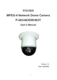
<strong>H.264</strong> <strong>Series</strong> 2-<strong>Megapixel</strong><strong>Network</strong> <strong>Camera</strong><strong>PL621</strong> / <strong>PL621</strong>EUser’s ManualVersion: 1.1Date: 10/24/2011
NoticesThis user manual is intended for administrators and users of the PiXORD <strong>Network</strong> <strong>Camera</strong>, includinginstructions for using and managing the camera on your network. The use of surveillance devices may beprohibited by law in your country. It is the user’s responsibility to ensure that the operation of such devices islegal before installing this unit for its intended use.Before the <strong>Network</strong> <strong>Camera</strong> is installed, all the safety and operating instructions should be carefully read andfollowed to avoid damage due to faulty assembly and installation. This also ensures the product is usedproperly as intended.Heed all warnings‣ Do not drop or strike this equipmentSensitive electronics inside the camera are vulnerable to excessive strike.‣ Do not install the equipment near any flames or heat sourcesExcessive heat could damage this equipment.‣ Do not cover cloth or to install this equipment in poorly ventilated places.Overheating could damage this equipment.‣ Do not expose this equipment to rain or moisture. Do not touch the power connection withwet handsRisk of short circuit, electric shock or fire‣ Do not damage the power cord or leave it under pressureRisk of fire or shock circuit‣ To reduce the risk of electric shock, do not remove the Cover (or Back).No user-serviceable parts inside. Misusage, improper, and negligence could damage thisequipment. Need to refer servicing to qualified service personnel.‣ Do not continue to operate if there appears to be fault.If the unit ceases to function, contact qualified service personnel for help.‣ All work related to the installation of this product should be made by qualified servicepersonnel or system installers.2
LiabilityPiXORD Corporation reserves the right to make corrections, modifications, enhancements, improvements,and other changes to its products and services at any time and to discontinue any product or service withoutnotice. Customers should obtain the latest relevant information before placing orders and should verify thatsuch information is current and complete. All products are sold subject to PiXORD Corporation’s terms andconditions of sale supplied at the time of order acknowledgment.PiXORD is not responsible or liable for the resale of its products with statements different from or beyond thespecification/parameters stated by PiXORD. Customers are responsible for their applications using PiXORDproducts. To minimize the risks associated with customer applications, customers should provide adequateoperating safeguards. PiXORD is under no obligation to provide any further technical support service orproduct/software alteration beyond PiXORD's representation.PiXORD products are not authorized for use in safety-critical applications where a failure of the PiXORDproduct would cause severe personal injury or death, unless officers of the parties have executed anagreement specifically governing such use.Reproduction of PiXORD information or datasheets with alteration is an unfair and deceptive businesspractice. PiXORD is not responsible or liable for any such statements.Every care has been taken of this manual. If there are any inaccuracies or omissions, please inform your localoffice. PiXORD Corporation cannot be held responsible for any typographical or technical errors. PiXORDCorporation is not liable or responsible for incidental or damages caused by mishandling.TrademarksAll names used in this manual for hardware and software are probably registered trademarks of respectivecompanies. PiXORD is a registered trademark of PiXORD corporation. All rights reserved.SupportIf you require any technical assistance, please contact your PiXORD reseller. You can connect to the InternetPiXORD’s website: www.pixord.com for below information,• Download user documentation and firmware updates at PiXORD Support( http://www.pixord.com/support/support.asp)• Find answers to resolved problems in the FAQ database. Or contact our FAE at technical support(http://www.pixord.com/contact2.asp)3
IntroductionPiXORD <strong>PL621</strong> <strong>Network</strong> <strong>Camera</strong> delivers superior <strong>H.264</strong>-AVC performance, state of the art design andfunction. <strong>PL621</strong> is specifically adapted for maximum performance indoor applications, such as commercial,banking, government buildings, schools, universities and airports.<strong>H.264</strong>-AVC video compression can lower bandwidth and storage requirements without compromisingimage quality; Motion JPEG is supported for increased flexibility, as well as multiple independent videostreaming.<strong>PL621</strong> value-added features include; on-board video motion detection, SD slot for storage recording, andtwo-way audio. P-600 PoE available, full PoE (IEEE-802.3af) feature supplies power to the camera via thenetwork, eliminating the need for power cables, reducing installation costs and complexity. Consequently,<strong>PL621</strong> is “Best in Class” for maximum performance IP video surveillance systems, demanding superiorimage quality, ease of installation, and intelligent video capabilities.4
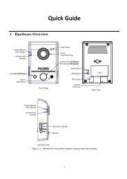
Installation1. Hardware Connection1. Prepare a PC with Ethernet link to the network2. Connect LAN port (RJ45) of the camera to a network switch/hub3. Connect power jack4. Ensure the power adaptor specification matches the power system (110V or 220V) and connect theadaptor to the outlet5. Check LED status (Power/<strong>Network</strong>)5
2. Software InstallationThe following software is necessary for the proper display and use of the <strong>PL621</strong> from the Web site. Thesoftware will be taken from the Software Package CD.IP InstallerThe IP Installer is used to locate and configure network cameras and video servers on the LAN. Thisutility is useful for conveniently configuring the network settings of the device, or for finding a deviceonce the network settings have been modified.To install the IP Installer, from the Software Package CD UI, select IP installer, then follow the on screeninstructions.XVID CodecAn <strong>H.264</strong> codec is applied for displaying the video stream and playing the recoded AVI files. If the videostream can’t be displayed or the recorded AVI files can’t be play on PC, install this software from theSoftware Package CD.VLCThough not necessary, this can be used for viewing the streaming without a Web browser.6
3. <strong>Network</strong> ConfigurationIP Installer is a utility that provides an easier, more efficient way to configure the IP address and networksettings of the devices. It even provides a convenient way to set the network settings for multipledevices simultaneously using the batch setting function. Moreover, IP Installer can save the networksettings for all devices as a backup and restore them when necessary.Preparation before IP Assignment1. Always consult your network administrator before assigning an IP address to your server in order toavoid using a previously assigned IP address.2. Ensure the <strong>PL621</strong> is powered on and correctly connected to the network.3. MAC Address: Each device has a unique Ethernet address (MAC address) shown on the label of thedevice as the serial number (S/N) with 12 digits (e.g. 000429-XXXXXX).*0004290000B14. Although the IP Installer is able to find and configure any <strong>PL621</strong> in the LAN except those that are behinda router, it is a good idea to set the host PC to the same subnet. In order to connect to the Web-baseduser interface of the camera, the host PC must be in the same subnet. For more information aboutsubnets, please consult your network administrator.Using IP Installer to Assign an IP Address to <strong>PL621</strong>1. Once IP Installer has been successfully installed on the PC, double click the IP Installer icon on thedesktop, or select it from Start > Programs > IP Installer > IP Installer > Launch IP Installer.2. Click the menu bar Tool > Search <strong>Network</strong> Device to search the device in the LAN.7
3. From the list, select the device with the MAC Address that corresponds to the device that is to beconfigured. The MAC Address is identical to the unit’s S/N (Serial Number).4. Double click the item to open the Property Page for the selected device or click the menu bar View >Property.5. After filling in the properties, click [Set] button to complete the configuration settings in the remotedevice while saving configuration in the PC. If click [Close] button, the configuration is only be saved inthe PC.8
Open the Web-based UI of the Selected camera1. To access the Web-based UI of the selected unit, run the View > Open Web on the menu bar.2. If the device has been configured correctly, the default Web browser will open to the home page of theselected device.3. If you find your browser is opened and automatically connected to the camera Home Page, it meansyou’ve assigned an IP Address to the unit successfully. Now you can close the IP Installer and start touse your camera.Verify and Complete the Installation from Your BrowserWhen browsing the Home Page at the first time with the Microsoft Internet Explorer TM , you must temporarilylower your security settings to perform a one-time-only installation of the ActiveX component onto yourworkstation, as described below:1. From the Tools menu, select [Internet Options]2. Click the [Security] tab and then click [Custom Level] button to see your current security settings.3. Set the security level to Low and click [OK].4. Type the URL or IP address of your camera into the Address field.5. A dialog box will pop up asking if the ActiveX control should be installed. Click [Yes] to start theinstallation.Once the ActiveX installation is complete, return the security settings to their original value, as noted above.9
Using the Web UIStart your Web browser and enter the URL or IP address in the Address field. The Home page of thecamera is now displayed.10
1. Live ViewVideo formatBit rateIP address of the cameraResolutionFrame RateDateButtonDescriptionClick for more general/advance camera settingsSelect languages among English, traditional Chinese and simplifyChineseCheck actual size to view the actual size (resolution) of the imageClick to trigger the alarm manuallyChoose among the 3 streams for viewing11
ButtonDescriptionFull screenListen the audio input from local endTalk functionRecord instant live videoSnapshot the image12
Configuration Pages ListVideo‣ General‣ Advance‣ External Video Source<strong>Camera</strong>:‣ General‣ AdvanceEvent‣ Event Server‣ Motion Detection‣ I/O Ports‣ Event ConfigurationSchedule‣ General‣ Storage<strong>Network</strong>‣ General‣ Advance‣ SMTP (E-mail)‣ DDNSSystem‣ Information‣ User‣ Date & Time‣ Server Maintenance‣ Log ServiceCustomize‣ Style Layout13
2. VideoGeneralVideo General Setting: Check each box to enable streams (max 3) for live viewingNote: Digital PTZ is only available with stream 2OSD Setting: Enable OSD to display camera name and date/time on the image14
AdvancedStream 1 Setting:‣ RTSP Path: It is the stream ID used for RTSP client streaming connection, such as VLC player.‣ Resolution: Choose image size from 320x240 to 1600x1200‣ Video Mode: Choose between variable bit rate (VBR) and constant bit rate (CBR)VBR-> Choose quality level from best to standardCBR-> Choose target bit rate range from 64 to 6000kb‣ Image Format: 2 kinds of format to choose from; MJPEG and <strong>H.264</strong>‣ GOP: Group of pictures‣ Frame Rates (FPS): Choose the number of frames to display per secondWith resolution 1600x1200, FPS can only set up to 15FPS. The rest can set up to 30FPS.Stream 2 Setting:Configuration of stream 2 is the same as stream 1.Note: Resolution can only be set to 320x240 or 640x480Stream 3 Setting:Only RTSP path, image format and frame rate can be adjusted, the rest of the settings are fixed.15
3. <strong>Camera</strong>General16
<strong>Camera</strong> General Setting:‣ Brightness, hue and saturation: Adjust the image for a better view‣ Rotation 180: Rotate the image by 180 degrees, so that the image becomes upside down. Thisfunction is useful when camera device must be physically installed in vertically reversed direction.Audio Setting:‣ Audio Enable: Turn on/off the audioWeb Record Setting:‣ Save Path / File name: Click on the “Browse” button to select the desired path to save as well asnaming the video file.Web Snapshot Image Setting:‣ Save Path / File name: Click on the “Browse” button to select the desired path to save as well asnaming the snapshotDefault:‣ Set [camera general setting] and [audio setting] back to defaultNote: Will not change the configuration of [Web Record Setting] and [web Snapshot Image Setting]Save:‣ Save the changes that have been made17
AdvanceWhite balance: Adjust the white balance according to the environmentExposure: Select the exposure frequencyMax Exposure Time: Increase / reduce the exposure time for lensMax Gain Control: image at low light control on how much noises are allowedInfrared (IR) Cut Filter: IR will activate depending on the light sensor, it is for better vision at nightColor / Mono Mode: Switch among color, mono or auto modeVideo External Output Format: Adjust the format according to the environment18
4. EventEvent ServerClick on the [Add FTP] to expand FTP server settingFTP Server:‣ Name: Give a name for the FTP server‣ <strong>Network</strong> Address: Input the network address of the FTP server‣ Upload Path: Choose the desired upload path for events‣ Port: Input the port number of the FTP server19
Login Information:‣ Username / Password: Input the username and password of the FTPClick [Remove] to delete selected event servers (circled in red)20
Motion Detection1To add a motion detection area:1. Click on [Add] to set up a detection area(Set up panel will be expanded)21
2342. Give a name to this window area3. Select the trigger level and sensitivity for this detection window (0~100, low~high)4. Select color for detection window5. Draw detection window on the image6. Once everything is done, click on [Save] to save the configuration made.22
Configured detection window will be displayed in motion detection list (circle in blue)Note: Maximum number of detection window is 10I/O PortsInput Ports Setting 1 and 2:‣ Name: The name of Digital Input1/2‣ Current State: Current Input stateOutput Ports Setting:‣ Name: The name of relay output‣ Current State: Current Output state23
Event Configuration1To add an event trigger, click on [Add] and setup panel will be expanded24
234562. Give a name to this event.3. Set the time interval between each trigger4. Set the time period for the trigger. Choose “Always”, “During time frame” or “Never”During time frame: Choose a day and the starting time then configure the duration time (168hrs = 24x7).For example if duration time is set to 168(hrs), it is the same as choosing “Always”5. Choose the triggering condition, “GPIN”, “Manual trigger”, “Motion detection” and “On boot”6. Choose the triggered event. “Upload images”, “Active Output port”, “Send email notification”7. Finally click on [Save] to save the configuration made.25
5. ScheduleGeneralDefine the day (specified by days of a week) and time (specified by each single hour) for that will be recordingduring the scheduled period. Note that only video data will be recorded. User can select which video streamshould be recorded, and the size of each sliced file. When the check box is ticked and setting is saved,recording process starts. Recording files are saved to the SD storage.26
StorageDisplay the storage information, includes disk size info, type and status. The warning message shows whenrecording is on process; SD card should not be removed during the recording process.*It is the best to format the disk first before using it.27
6. <strong>Network</strong>GeneralDevice IP configuration, includes DHCP, Static IP setting and PPPoE. “Enable ARP/Ping” enable device toaccept ARP or ping packets from the network. Disable this option may provide extra security from intentionalping.*After all settings are made please reboot the camera to activate PPPoE. You will receive email with IPaddress later.28
AdvancedEnable or configure other network functions.NTP: Configure a NTP (<strong>Network</strong> Time Protocol) server, so that the device system date and time can besynchronized with a specified Time Server. This configuration is provided for one of the potions of systemdate/time adjustment.HTTP: set the HTTP port that will be applied for Web UI access.RTSP: set the RTSP (Video) port for video data transmission.HTTPS: Enable/Disable Http security function.Bonjour: Enable Bonjour service, so that the device can be discovered with “Bonjour” service applied.UPnP: Enable UPnP, so that the device can be discovered in an UPnP Compliant <strong>Network</strong>.NAT Traversal: Enable NAT traversal, so that client from Internet can have access to the devices behind theRouter.Note: with UPnP enabled, the IP Sharing device (Router) capable of UPnP function will automatically benoticed with the device’s NAT port.29
SMTP (E-Mail)Configure an email host in the device that will send email on behalf of the configured email account in acircumstance like sending an email notice to a specified mail address (Event Configuration).Sender: Complete the Mail Server, Server Port, Authentication information (if required) and the sender emailaddress.Receiver: the receiver email address31
DDNSDynamic DNS configuration; the network device can be assigned with a host name by registering this service(Internet access required).Host Name: Assigned name that will be used for access to the deviceUser Name/Password: Account authentication for logging to this serviceUpdate Time: Periodically, the device updates its access info to sever in the configured time.Response: the device responds the connection info.32
7. SystemInformationLists of System and <strong>Network</strong> configurations33
UserLogin users for Web access and operations; authentication required. The Check box is for anonymouslogging on to the live view page. Logging for further configurations will still require user name and password.Follow the conditions shown to add different users with different authority.34
Date & TimeSystem date/time configuration. Options of synchronizing with PC and NTP server are provided for automaticadjustment.35
Server MaintenanceThis page provides tool for system maintenance; Reboot and Load default settings, as well as functionalitiesof launching upgrade process, backup/restore user settings and language defines.36
Log ServiceMost system operations and / or process will be kept in a log system. The link provides the review of theserecords.37
Use Custom Settings: The modifications allowed are change of Background / Text Color, Background picture,Title, Description, Logo and etc.39
FAQI/O Terminal Connector - Pin AssignmentPin Function1 COMMON2 RELAY_NO3 DGND4 DIGI input5 DGND6 Load defaultRestore Factory DefaultTo restore factory default, please follow the steps:1. Unplug the power jack to turn off the camera2. Short pin 5 and pin 6 with a wire3. Plug in the power jack to turn on the camera. The power LED will start flashing in a short while.4. Break the short when the LED starts quick flashing. Wait for a few minutes the device should beset back to factory default.40