
Create successful ePaper yourself
Turn your PDF publications into a flip-book with our unique Google optimized e-Paper software.
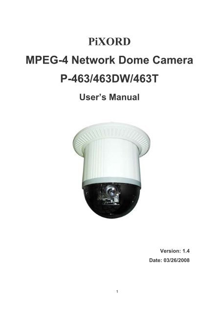
PiXORDMPEG-4 Network Dome CameraP-463/463DW/463TUser’s <strong>Manual</strong>Version: 1.4Date: 03/26/20081
ContentINTRODUCTION........................................................................................................................................................................4WHAT IS NETWORK DOME CAMERA?..............................................................................................................4FEATURES ...........................................................................................................................................................................51 PHYSICAL CONNECTIONS................................................................................................................................................71.1 STRUCTURAL ELEMENT......................................................................................................................................................71.2 CONNECTION JACK AND CABLE REQUIREMENT..................................................................................................................81.3 DIP SWITCH SETTING.......................................................................................................................................................101.4 NDC ID ADDRESS SETTING REFER CHART ......................................................................................................................112 INSTALLATION...................................................................................................................................................................122.1 INSTALLATION PREVIEW ...................................................................................................................................................122.2 HARDWARE INSTALLATION ...............................................................................................................................................132.3 SOFTWARE INSTALLATION ................................................................................................................................................252.4 NETWORK CONFIGURATION..............................................................................................................................................263 USAGE OF WEB-BASED USER INTERFACE................................................................................................................303.1 BROWSE LIVE VIDEO........................................................................................................................................................303.2 VIDEO AND AUDIO RECORDING........................................................................................................................................333.3 VIDEO CONFERENCE.........................................................................................................................................................344 CONFIGURATION OF WEB-BASED USER INTERFACE ...........................................................................................374.1 CONFIGURATION PREVIEW................................................................................................................................................374.2 CONFIGURATION OF A/V SETTING....................................................................................................................................384.3 SETTING EXTERNAL SOURCES ..........................................................................................................................................424.4 PTZ SETTINGS..................................................................................................................................................................434.5 ON SCREEN DISPLAY ........................................................................................................................................................484.6 CONFIGURATION OF NETWORK SETTING ..........................................................................................................................494.7 CONFIGURATION OF SYSTEM ............................................................................................................................................534.8 CONFIGURATION OF EVENT ..............................................................................................................................................575 ADVANCED SETTINGS FOR P463...................................................................................................................................605.1 CALL OUT THE OSD SETUP MENU ...................................................................................................................................605.2 SET UP FUNCTIONS...........................................................................................................................................................616 ADVANCED SETTINGS FOR P463DW............................................................................................................................706.1 CALL OUT THE OSD SETUP MENU ...................................................................................................................................706.2 SPECIAL FUNCTIONS.........................................................................................................................................................716.3 CAMERA SETTINGS...........................................................................................................................................................746.4 LENS CONTROL ................................................................................................................................................................867 ADVANCED SETTINGS FOR P463T................................................................................................................................881
7.1 CALL OUT THE OSD SETUP MENU ...................................................................................................................................887.2 SETUP FUNCTIONS ............................................................................................................................................................908 SURVEILLANCE SYSTEM CONFIGURATION ..........................................................................................................1018.1 NDC AND KEYBOARD ....................................................................................................................................................1018.2 INITIAL POWER UP INSPECTION ......................................................................................................................................1038.3 OPERATING NDC WITH KEYBOARD................................................................................................................................1039 SPECIFICATIONS.............................................................................................................................................................113APPENDIX A. UPGRADING THE SOFTWARE.................................................................................................................118APPENDIX B. UPGRADE CUSTOM WEB PAGES ...........................................................................................................121APPENDIX C. EMERGENCY FACTORY DEFAULT........................................................................................................123APPENDIX D. QUICK REFERENCE TABLE FOR KEYBOARD CONTROL..............................................................124APPENDIX E. TROUBLE SHOOTING................................................................................................................................1262
WARNING and PRECAUTIONSPlease read the manual before attempting installation or operation !Please be aware of the following:1. Don't use any chemical detergent to clean the machine surface, use a damp cotton cloth only. Regularly clean the domecover to ensure more accurate focusing.2. Please install the Network Dome Camera in a dry area; water and high humidity may cause damage on internal parts.External housing should be used for outdoor installations.3. Please use parts supplied by the manufacturer only, any unqualified part using in the equipment may violate the warranty.4. Avoid installing the equipment in an unstable surface. Ensure that the equipment is attached to something that is fixedsolidly in place. Falling equipment may injure personnel and damage the equipment.5. Do not install the equipment near any flammable materials as they may cause a fire or personal injury.6. Avoid running video cable and signal cable through or passing interference sources such as video waves, broadcaststations, power generators, elevator motors or high voltage areas, etc. as they may cause interference.7. Ensure the power cable is properly attached. Improperly attached cables may cause a serious short circuit or fire.8. Correct cable connection is important. Do not place any object on the connection cable and change the cable if there isdamage on cable. Violation may cause short circuit, fire and injury.9. Make sure ground is well connected to avoid damage caused by lightning.10. Do not put any foreign objects inside the equipment and do not spray any liquid on equipment. This will avoid short circuitdamage.11. Do not touch power connection with wet hands to avoid short circuit or electricity shock.12. Do not apply smash-force on the equipment. Violation may cause damage.13. Do not install the equipment in a location that may expose the equipment directly to sunlight. Violation may cause colorfading or damage.14. Do not install the equipment in high temperature or low temperature environment to avoid damage. The normaloperational temperature is between -5 o C ~ +50 o C.15. The Network Dome Camera contains high sensitive electric parts inside. Do not try to repair them without qualifiedpersonnel.16. Turn off the power immediately and contact the technician when the following occurs:A. Damage on power cable or plug.B. Water leak into the equipment.C. The Network Dome Camera can not be operated normally.D. Equipment falling on ground or damage on external case.E. Unusual occurrence.17. Warning: Do not try to repair the equipment. Only a qualified technician may disassemble and repair the equipment. Shutoff the power before disassemble the equipment and don't put power on unless the case is completely assembled.3
IntroductionWhat is Network Dome Camera?The Network Dome Camera (“NDC” here and after) is an Internet-based digital Network Speed Dome Camera, it hasbuilt in Pan/Tilt/Zoom and CCD module to distribute the compressed live video into Intranet/Internet through Ethernetconnection.NDC can move (Pan/Tilt/Zoom) the view point to get the best monitoring angle easily via standard browser such asInternet Explorer TM or Netscape TM .NDC is self-contained Web Server. Users could access the Network Dome Camera just like browsing website overInternet using standard browser such as Internet Explorer TM or Netscape TM , and do all the management, configuration,and monitoring easily.NDC contains an MPEG-4 image compression chipset capable of delivering streaming, constant or variable bit rateMPEG-4 video over the network in real-time.4
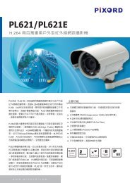
FeaturesThere are 3 types of the Network Dome Camera – P463 (25X Optical Lens) and P463DW (Wide Dynamic Range / 25XOptical Lens) P463T (Tracking / 25X Optical Lens). The specifications and functions will be different between thesetypes.Common Features• 360 o continuous rotation• High speed rotation and tilt, speed range varies from 0.18°/sec ~ 360°/sec• Up to 128 programmable preset positions• Preset positions auto scanning• 6 alarm inputs, 1 alarm output can be set as NO (normally open) or NC (normally close) for each NDC• Two types of alarm response mode: Lock Mode, Release Mode• 180° Horizontal Instant Flip• Built-in 1/4” Interline Transfer CCD• Automatic / <strong>Manual</strong> Focus• Automatic / <strong>Manual</strong> Iris Control• Auto Gain Control (Sensitivity adjustable)• White Balance Control (Auto, Indoor, Outdoor)• Back Light Compensation• RS-485 control interface• Up to 64 NDC configuration• Compatible with PC control (protocol required)• 12V DC voltage input (power supply options: AC 90~260V or AC 24V)• Flexible Mounting: Indoor-embedded and attached types; Outdoor-with weather resistant housingP463 & P463DW Common Features• Auto Focus Lens: built-in 25X optical zoom lens with focal length 3.8 ~ 95.0mm• True Day & Night Camera: Color / Mono Switch (IR Cut Filter)• 570 TV Lines Mono Resolution, 480 TV Lines Color Resolution• 0.01 Lux Sensitivity (Mono), 0.1 Lux Sensitivity (Color)• Auto Focus Modes Selectable• <strong>Manual</strong> Iris Speeds Selectable• Back Light Compensation Zone Selectable• Gamma Adjustment• On-Screen Setup Menu5
P463T• Auto tracking movement.P463• Aperture Correction AdjustmentP463DW• 2.56X Digital Zoom: For a total of 64X combined digital and optical zoom.• Wide Dynamic Range: Uses two Shutter Speeds in alternative video fields and combines two fields into oneprogressive scan frame. As a result, combined field yield a frame of high-quality image.• Dynamic Privacy Zone: With this function, unwanted or prohibited areas within an image can be maskedappropriately.• Preset Scene File: Preset setting such as BLC, AE mode, Shutter speed and AF mode can be saved as SceneFile and apply to other presets with similar circumstances to improve efficiency.• Slow-speed Shutter• Image Memory Function: Horizontal/Vertical Flip, 180 o Image Rotation, Field Image Capture.6
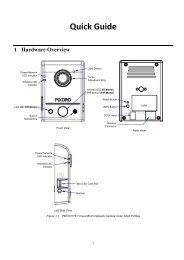
1 Physical Connections1.1 Structural Element654710389211. Dome Cover 6. Video In /Out Jack2. Camera Case 7. Power In Jack3. Ethernet Port 8. Alarm In/Out Jack4. Power / Network Status LED 9. RS-485 In/Out Jack5. Audio Line In Jack 10. Camera Base7
1.2 Connection Jack and Cable RequirementPower In Jack• DC12V Input Voltage, Power Consumption 1.2Adc, Center Pin 2.0mm• Require Cable: 18 AWG x 2CVideo Out BNC Jack• Video Signal Output CVBS 1.0Vpp 75Ω BNC• Recommend Data Cable:5C2VAlarm In/Out Jack• Each NDC contains 6 alarm inputs and 1 alarm output• Alarm Input Voltage 5.6V max, Output 0.5A 120Vac/ 1A 24Vdc• Recommend Data Cable: UL 26 AWG 80 C 300V UL 24 AWG 80 C 300V8
RS-485 In/ Out Jack• RS-485 Input (TXDI+, TXDI-) to receiver signal from keyboard, matrix, DVR or multiplexer through twisted paircable.• RS-485 Output (TXDO+, TXDO-) sending out signal to next NDC through twisted pair cable.• Recommend Data Cable: 2547 VW-ISC UL 24 AWG x 2C• Transmission Distance: Max. 1 Kilometer* When 24VAC PSU is used, the recommend cables are:• UL SPT-1 VW-1 18AWG x 2C• UL SPT-2 VW-1 18AWG x 2C• UL SUT 105C VW-1 18AWG x 3CThe distance between 24Vac PSU and fast dome cannot exceed 200 meters.Ethernet• Standard IEEE 802.3 10 /100 Base-T portPower/Status LED• Power On: constant red.• Emergency factory default (appendix C): Blinking orange (i.e. red mix with green).Network LED• Network Link (connected): Constant red.• Networks have activities: Blink red.• Data sent out from server: Blink green.• Network disconnected: Constant slow blinking green.• Upgrading software (appendix A): Constant slow to fast blinking of orange.9
1.3 DIP Switch SettingFan Power SwitchTurn the number 2 switch to ON position to activate the internal fan. This will maintain the temperature inside andmake electric parts life.Alarm Mode SwitchAlarm Mode can be set as Lock or Release mode. Turn number 1 switch to ON position to choose Release mode.Turn number 1 switch to OFF position to choose Lock mode. The NDC has 6 alarm inputs and 1 output, whichcan be set either NC (normally close) or NO (normally open) mode. Turn number 2 switch to NO position tochoose NC mode. Turn number 2 switch to OFF position to choose NO mode.Camera Function SwitchFor P463, P463DW (25X optical lens model) and P463T, please refer to “6. Advanced Settings for P463”, “7.Advanced Settings for P463DW” and “8. Advance Settings for P463T” for details.10
1.4 NDC ID Address Setting Refer ChartUp to 64 NDC can be serial linking in one system. Therefore each dome is addressing by ID switch located at the baseof the NDC. Below is the address setting for camera 1~64:11
2 Installation2.1 Installation PreviewThere are 3 mains steps required to perform a successful installation:• Hardware installation• Software installation• Network configurationHardware installation consists of connecting cables to the NDC including network, video, and power cables.Software installation consists of the installation of software that is necessary to properly view the video from the NDCor to configure the NDC itself. The software includes:• IP Installer -- a utility for locating devices and configuring network settings on a LAN.• Component Installer -- installs all ActiveX components used by the device for things such as video display andconfiguration.• Macromedia Flash Player -- necessary for displaying some components of the Web UI.The following are not necessary, but may be used for convenience:• Recording Software -- displaying and recording up to 16 channels simultaneously. Both the MPEG-4 and MJPEGdevices are supported.• Xvid -- a MPEG-4 codec. If no other MPEG-4 codecs (ie. DivX, 3ivX, ffdshow, etc.) are installed on your computer,the Component installer will install this for you.• QuickTime or VLC -- though not necessary, this can be used for viewing the MPEG-4 stream without a Webbrowser.Network configuration consists of modifying the network settings for the NDC in order to successfully connect to thedevice.12
2.2 Hardware Installation– Indoor Installation Structural Drawing13
– Outdoor Installation Structural Drawing (Pendant Mounting)14
– Embedded Mounting (False Ceiling)15
Note: After dome cover is attached, use glass-cleaning cloth to clean dome cover. Unclean dome cover mayaffect camera performance.17
– Attached Mounting (Fixed Ceiling)18
Note: After dome cover is attached, use glass-cleaning cloth to clean dome cover. Unclean dome cover mayaffect camera performance.19
– Pendant Mounting (External Housing)20
Note: When the NDC is installed inside outdoor housing, please don’t attach dome cover. Violation may affectcamera performance.23
2.3 Software InstallationWith the exception of the Macromedia Flash Player all the software that is necessary for the proper display and use ofthe NDC is available on the included CD or from the Web site. For the following installation procedures it is assumedthat all installation media will be taken from the CD.IP InstallerThe IP Installer is used to locate and configure network cameras and video servers on the LAN. This utility isuseful for conveniently configuring the network settings of the NDC, or for finding a device once the networksettings have been modified.To install the IP Installer, from the installation CD UI, select IP installer, then follow the on screen instructions.Component InstallerThis will install all ActiveX components used by our devices for video display and device configuration.Adobe Flash PlayerPlease visit the Macromedia Web site at http://www.adobe.com/downloads/ to download and install the FlashPlayer.25
2.4 Network ConfigurationIP Installer is a utility that provides an easier, more efficient way to configure the IP address and network settings of theNDC. It even provides a convenient way to set the network settings for multiple devices simultaneously using the batchsetting function. Moreover, IP Installer can save the network settings for all devices as a backup and restore themwhen necessary.– Preparation before IP Assignment• Always consult your network administrator before assigning an IP address to your server in order to avoid using apreviously assigned IP address.• Ensure the NDC is powered on and correctly connected to thenetwork.• MAC Address: Each NDC has a unique Ethernet address (MACaddress) shown on the bottom of the NDC as the serial number*000429000094(S/N) with 12 digits (e.g. 000429-XXXXXX).• One final note, although the IP Installer is able to find and configure any NDC on the LAN except those that arebehind a router, it is a good idea to set the host PC to the same subnet. In order to connect to the Web-based userinterface of the NDC, the host PC must be in the same subnet. For more information about subnets, pleaseconsult your network administrator.– Using IP InstallerAssigning an IP Address to NDC1. Once IP Installer has been successfully installed on the computer, double click the IP Installer icon on thedesktop, or select it from Start > Programs > PiXORD Corporation > IP Installer > IP Installer.2. The IP Installer window is displayed below.3. Click the menu bar Tool > Search Network Device to search the NDC in the LAN.26
4. From the list, select the device with the MAC Address that corresponds to the device that is to be configured.The MAC Address is identical to the unit’s S/N (Serial Number).5. Double click the item to open the Property Page dialog box for the selected device or click the menu bar View> Property.6. After filling in the properties, click [Synchronize] button to complete the configuration settings in the remoteNDC while saving configuration in the PC.If click [OK] button, the configuration is only be saved in the PC.27
5. A dialog box will pop up asking if the ActiveX control should be installed. Click [Yes] to start the installation.6. Once the ActiveX installation is complete, return the security settings to their original value, as noted above.29
3 Usage of Web-based User InterfaceStart your Web browser and enter the IP Address of your NDC Camera in the Address field. The Home page of thecamera is now displayed. The Web UI can present up to 4 video source indicating 4 video channels. Each channel canbe shown individually or in one of 4 split windows.The status of thevideo streamFull ScreenMaximizes to view the selectedchannels into full screen123 4Video stream fromcamera (Local videosource)External videosources3.1 Browse Live Video– Menu Language SelectionThe online Web-based User Interface can allow the user to select 3different languages: English, Traditional and Simplified Chinese.Such display will not affect the original configuration for the language,allowing multiple users to have different languages concurrent views. Inorder to make the language change permanent, settings must be modifiedthrough the Configuration page, and saved once it is made.30
– Video Channel SelectionThe Video Channel allows the users to choose viewing 1 channel at a time or4 channels at the same time.CH1 displays the video stream of the NDC.CH2~4 display the video stream of the IP Camera or Video Server thatconnected the device via network.• Select “All” to display the local video stream (Channel 1) as well as 3external video sources (Channel 2 ~4).• Select 1~4 to display the video stream of single channel.• Select Actual to display the video stream at the actual resolution.– Pan / Tilt / Zoom ControlThe PTZ control panel allows the users to pan, tilt and zoom the dome.• Speed : Click on the arrow button and select the speed of the Pan and Tilt movements. Values run from 1 to 7.Being 1 the slowest and 7 the fastest.• Preset Point : Click on the arrow button and select the preset point from the pull-down list for quick view.• <strong>Manual</strong> Pan/Tilt : Click on the 8-directions button to move the camera to that direction. Click on the rectanglebutton to stop the movement.• 180 o button : The viewing will turn 180 degrees.• Zoom - : Click on this button for Zooming Out.• Zoom + : Click on this button for Zooming In.• Iris + : Opens the iris and brightens the picture.• Iris - : Opens the iris and reduces glare.• Focus + : The target will become nearer.• Focus - : The target will become farther.• Auto Iris : The lens will automatically adjust itself for optimum iris.• Auto Focus : The lens will automatically adjust itself for optimum focus.• Auto Pan : Click on the arrow button to activate; click on the rectangle button to stop. When the Auto Pan functionis activated, the NDC will auto touring the preset groups entered. Only the first 16 preset points of the NDC can beset to auto pan mode and first 6 preset points are corresponding with the 6 alarm.31
To pan/tilt/zoom the external video sources CH2~CH4, click on [CH2~4PTZ Control] button to open a new window. Select the channel in thiswindow to display the PTZ control panel for operation.– Digital Zoom SelectionThe Digital Zoom enable user to select the digital size for the channels.• Select [x1], [x4] or [x9] to enlarge the video.• Select [Draw Mode] and then use mouse to select an area on thevideo for enlargement.– On/Off the Audio, and Rotate the VideoThe [Video Status] item allows the users to see the current settings of the selected channel. It also includes thefunction for audio control, video rotation and record the video/audio for the selected channel.Select the ChannelClick on the number tab, and status for the selected channel will be displayed. The settings can be setup inConfiguration page.On/Off the AudioSelect [On] or [Off] button to enable or disable the audio for selectedchannel.Rotate the VideoClick on [Rotation] button to temporary rotate the selected video 90degrees clockwise direction. This feature is to have natural view forcameras that are hooked up on walls and/or vertical positions.32
3.2 Video and Audio RecordingBefore recording the selected channel, you can check the information of recorded file by clicking on [RecordingInformation] item. The settings can be changed in Video Conference page.• To record the video and audio for each channel:1. Click the channel number on the tab under [Video Status].2. Click on [<strong>Manual</strong> Recording] button, it will start recording live videoand audio of the selected channel. A “REC” message will display onthe video.3. The device can record multiple channels at the same time. To recordother channels, just repeat step 1 and 2.4. To stop recording, select the channel from the tab and then click[<strong>Manual</strong> Recording] button again, the “REC” message will disappearand the recording is stopped.• By default, the recorded file will be saved in a folder namedC:\PiXORD\Recfile\pppp\CHx\♦♦pppp : The model number of the devicex : The number of the recorded channel• The default filename will be named under Locals_Rec-yyyymmdd-hhmmss.avi♦♦♦♦♦♦yyyy : Current Yearmm : Current Monthdd : Current Datehh : Current Hourmm : Current Minutess : Current second• The file will be saved as an AVI file, which can be play back with most media players.• The video is always recording with the actual direction. It will not be affected by the rotation of viewing.33
3.3 Video ConferenceClick [Video Conference] to open the conference page.Rotate this video forviewingClick this button to openthe Configuration pageOn/Off the audio of thisvideo streamClick this button backs tothe Home pageSettingConfigure the settings forRecordingRecordStart recordingStopStop recordingCameraSelect the remotedevice– Control the Video in Location WindowPTZ ControlTo control the dome camera, use the buttons on the PTZ Control panel to pan, tilt and zoom the camera.• Zoom - : Click on this button to Zooming Out.• Zoom + : Click on this button to Zooming In.• Focus + : The target will become nearer.• Focus - : The target will become farther.34
• Speed : Click on the UP/Down arrows and select the speed of the Pan and Tilt movements. Values run from 1 to 7.Being 1 the slowest and 7 the fastest• <strong>Manual</strong> Pan/Tilt : Click on the 4-directions button to move the camera to that direction. Click on the rectanglebutton to stop the movement.• Preset Point : Click on the number buttons to select a preset position for quick view.– Setting for Video RecordYou can change the settings for recording by clicking on [Setting] button in Location window.• Reserve Space : Set the total file space for therecording.• Max File Length : Set the file space that a single filewill be using.• Save File Path : Indicate which folder should the filebe saved to.• Location File Name : Input the name for the file thatrecorded from the location device.• Remote File Name : Input the name for the file thatrecorded from the remote device.• Cycle Recording : This feature determine if the oldspace should be used or not for the recording. Make acheck mark in order to enable this function. If youenable this feature, old files will be deleted• Sync to TimeStamp : This feature enables the file to be saved according to the time. When the video file isdisplayed, the video will make a match between the frames and the time.• Apply : Click this button to save the changes made.• Return : Click this button returns to the live video of the location device.• Record/Stop : Click [Record] button to start recording. Click [Stop] button to stop recording.– Select the Remote DeviceSelect the camera from the pull-down list, the video ofthe remote device will be displayed.There are 4 cameras can be selected as the Remotedevice. The first three are set up in the Configurationpage; the last one can be set up by clicking [Camera<strong>Manual</strong> Setting] button.35
– <strong>Manual</strong>ly Set Up Additional CameraThis feature allows the user to temporary set an additional video source for the remote device.Note: This camera will be removed after leaving or closing the Web page.Click on [Camera <strong>Manual</strong> Setting] button on the Remote window, and configure the following settings:• IP address : Enter a valid IP address from an IP Camera or Video Server.• Http Port : Enter the port number used for the IP address for network connection.• Username/Password : Enter the respective Usernameand Password if applicable. If no user has been set forthe device, the default value should be root and passrespectively.• Video Channel : If the selected camera is connected to aVideo Server, select the channel of the Video Server.• Video Type : Select MJPEG or MPEG4. The type mustmatch the external source provided.• Rotation : Rotate the video for view. Rotation degreesrun from 0 to 270 degrees.♦♦♦♦0: 0 degree1: 90 degrees2: 180 degrees3: 270 degrees• RTSP Port : Enter a RTSP Port used for streaming in case the external source is a MPEG4 device.• Name : Enter a name for the device.• PTZ Model : Enter a PTZ model.• Product Type : Select from MJPEG, MPEG4 Video Servers or IP Cameras. Please refer to the original documentof the device for a better description.• Test : Before submitting the information, click on this button to validate the video connection and the live video willbe displayed if the settings are correct.• Apply : Click this button to save the changes made.• Return : Click this button returns to the live video of the remote device.36
4 Configuration of Web-Based User InterfaceThe Configurations of the NDC are presented as links in the margin of the Configuration Page. Simply click therelevant link for the settings you want to configure.4.1 Configuration PreviewA/V SettingsFunctionsGeneralDescriptionSet the parameters of video and audio, and adjustthe image of the device.External SourcesSet the video source for channel 2 to 4, usingdigital inputs (IP Address).PTZ SettingsTo control the PTZ device and set the presetpoints.On Screen DisplaySet the text and location to display on the video.Network SettingsFunctionsGeneralDescriptionAssign an IP Address and configure the relevantnetwork parameters to the device.DDNSThe DDNS (Dynamic Domain Name Service) isused to access the NDC with an easy memorizedname such as http://demo.ddns.com instead ofhttp://192.168.0.200.SystemFunctionsSystem InformationDescriptionSet various information about the name of thedevice and the language type, etc.Time ConfigurationUserFirmware UpgradeSet the Date and Time.Add and delete users and passwords.Browse firmware location for upgrading37
EventFunctionsGeneralDescriptionEnable/disable the event trigger and select theaction when triggered.Motion AreaEmail / FTPSet the area on video for motion detection.Input the Email and FTP address to receive alertmessage or snapshot, sent by event trigger.OthersFunctionsLiveRebootDescriptionReturns to the Live Video display.Close the Web browser and reboots the device.4.2 Configuration of A/V Setting– Basic A/V Settings• Audio : Enables and Disables the audio stream.• ResolutionThere are 3 different resolutions to choose from:♦♦♦D1: 720x480 NTSC / 720x576 PAL (DVD Standard resolution)SIF: 352x240 NTSC / 352x288 PALQSIF: 176x120 NTSC / 176x144 PAL38
• Frame Rate : The frame rate can be set between 5 to 30 FPS.• Encoder FormatFormat can be selected for:♦♦♦MPEG4 constant bitrates: Select MPEG4 and CBR.MPEG4 variable bitrates: Select MPEG4 and VBRMotion JPEG.• BitrateFor Motion JPEG format, there are 4 variable bitrates between Low and High quality.For MPEG4 format, there are 12 different constant bitrates to choose from 64Kbps to 4Mbps, and 4 variablebitrates between Low and High quality.If you are planning on using the device on an Internet connection, it is recommended that you select a constantbitrate that corresponds to your actual upload speed. It is also recommended that you modify the frame rate andresolution as well, otherwise the video stream may become blocky or otherwise distorted. The recommendedsettings for low-speed network connection are as follows:♦♦♦♦♦♦64Kbps:128Kbps:256Kbps:512Kbps:768Kbps:1Mbps:recommended settings are [QSIF, FPS
– Advanced A/V Settings• InterlacingThere are 2 modes available: Interlaced or Progressive.Interlaced mode is a storage mode. An interlaced video stream contains fields rather than frames, with each fieldcontaining half of the lines of a frame.A progressive video stream consists of only full frames.Interlaced video streams can bring a lower bitrate but may cause lower quality.• TV Standard : The TV standard can be set among these 3 formats NTSC, PAL and SECAM.• Sequence ModeThere are 2 different modes available:♦♦I-frames onlyI-frames and P-framesP-frames, or predictive frames, are predicted based on prior P or I-frames plus some additional data. They have amuch higher compression ratio than I-frames.I-frame only mode has very little compression resulting in large file sizes.I-frame and P-frame mode offers relatively good compression with medium file sizes. Although this requires morework on the host PC to decode the video.• GOP Size: GOP stands for Group Of Pictures. It defines the number of frames from one I-frame to the next. Sincean I-frame uses very little compression, while P/B frames use much higher compression, a larger GOP sizeresults in smaller file sizes.• Peak Bitrate: This is used to set a maximum bitrate that can be achieved. This is useful for setting bitratesbetween the values that are available from the Video Encoder bitrate list.• Apply: Click this button to save the changes made.40
– Image Adjustment• Contrast, Brightness, Hue and Saturation : The value can be adjusted from -100 to 100.• Rotation : Rotation degrees run from 0 to 270 degrees for a permanent digital position.♦♦♦♦0: 0 degree1: 90 degrees2: 180 degrees3: 270 degrees• Load Default : Click this button to set the image adjustments back to factory default.• Save : Click this button to save the changes made.41
4.3 Setting External Sources• Video Select : Select the channel this external source will be displayed.• IP Address : Enter a valid IP address from an IP Camera or Video Server.• Http Port : Enter the port number used for the IP address for network connection.• Video Type : Select MJPEG or MPEG4. The type must match the external source provided.• Rotation : Rotation degrees run from 0 to 270 degrees for a permanent digital position.♦♦♦♦0: 0 degree1: 90 degrees2: 180 degrees3: 270 degrees• Video Channel : If the external source is a camera connected to a Video Server, select the channel of the VideoServer.• Username/Password : Enter the respective Username and Password if applicable. If no user has been set for thedevice, the default value should be root and pass respectively.• RTSP Port : Enter a RTSP Port used for streaming in case the external source is a MPEG4 device.• PTZ Model : Choose a PTZ model.• Name : Enter a name for the device.• Product Type : Select from MJPEG or MPEG4 Video Servers or IP Cameras. Please refer to the originaldocument of the device for a better description.• Test : Before submitting the information, click on this button to validate the video connection and the live video willbe displayed if the settings are correct.• Apply : Click on this button to save the changes made.42
4.4 PTZ SettingsSetting ID for NDCSelect an ID number to match the IDaddress set by the dome camera.Managing Preset PointsManaging the Preset Points for quickview and auto pan.Changing Lens SpeedSwitching the lens speed betweendefault setting and manual setting.Setting Day / Night ModeAdvanced Function Setup for NDCThis pair of buttons is for call out the OSD Setup Menu, and setup more functions.– Setting the ID for Network Dome CameraTo select an ID number to match the ID address set by the NDC ID switch:1. Click on the arrow button beside Camera ID and select the number from the pull-down list.2. Click on [Apply] button to confirm the selection.43
– Operating the Dome CameraTo control the dome camera for viewing, follow the description shown on below:Pan / Tilt the Dome CameraTo control the pan and tilt movement of the dome camerasimply click on the buttons:• To pan or tilt, just click on the 8-directions buttons for thedesired direction.• To adjust the speed of the movement, just click on thearrow button beside “Speed” and select the desiredspeed from the pull-down list. The higher the numberselected, the faster the speed.180 o RevolveThe viewing angle will turn 180 o .Zoom Lens Control• To zoom in: Click [+] button, the viewing angle becomesnarrower and target will become enlarged on the screen.• To zoom out: Click [-] button, the viewing angle becomeswider and target will become smaller on the screen.Iris ControlThe purpose of iris control is to adjust brightness on target. Itcan be set as Auto Iris or <strong>Manual</strong> Iris.• Iris open: Click [+] button, to open the iris and brightenthe picture.• Iris close: Click [-] button, to open the iris and reduceglare.• Auto iris: Click the arrow button beside “Auto Iris”, thelens will automatically adjust itself for optimum iris.Focus ControlThe focus function can be set as Auto Focus or <strong>Manual</strong>Focus.• <strong>Manual</strong> focus near: Click [+] button, the target willbecome farther.• <strong>Manual</strong> focus far: Click [-] button, the target will becomenearer.• Auto focus: Click the arrow button beside “Auto Focus”,the lens will automatically adjust itself for optimum focus.44
– Preset Point SettingThere are 128 individual preset points. Each preset stores the exact position of the camera and automatic pan, tilt,zoom, focus and iris setting. Once the data is set, the preset can be recalled for viewing, or the presets can be set forauto pan.Note: Only the first 16 preset points of the device can be set to auto pan mode and first 6 preset points arecorresponding with the 6 alarm inputs.Selecting Preset PointClick on the arrow button and select the desired numberfrom the pull-down list.Setting Preset Dwell TimeClick on the arrow button and select the desired value fromthe pull-down list.Setting Preset SpeedClick on the arrow button and select the desired value fromthe pull-down list.Save / Remove Preset Data• Click on [Save] button will save the current data as apreset point.• Click on [Remove] button will erase all 128 preset points.Activate / Stop Auto Pan• Activate: Click the arrow button.• Stop: Click the rectangle button.Selecting Preset Group for Auto PanSelect the groups by clicking on the check boxes, then click[Submit] button to save the changes made.Setting Preset Point1. Select a preset point. (If this point has been set previously, the following procedure will change the previoussettings after saving)2. Move the camera to the desired view position. (Refer to the previous page)3. Adjust the zoom, focus and iris of lens. When set up preset point, using manual focus will provide both clarityand stability of image. (Refer to the previous page)4. Set preset Dwell time. The dwell time means the time user wants to view on certain preset point under AutoPan. The Dwell time can be set between 1 ~ 255 seconds.45
5. Set preset speed. The speed the dome travels to that preset point can be adjusted between 10 to 250seconds.6. The presets Group 1 ~ 4 (First 16 preset points) can be entered a name for identify. Just fill the text string intothe Position Name field.7. Save the preset point. Once the above steps have been completed, the information must be stored or it willnot be memorized by the system.Note: For the first 16 presets on each dome, the above steps must be repeated. For presets 17 ~ 128 there isa default speed and dwell setting so steps 4 and 5 are not required.Setting Preset Group for Auto PanThe purpose of setting preset group allows the management of the 16 preset points before Auto Scanning. Thefirst 16 preset points are separated into 4 groups. Preset group must be set for the auto pan reference.• Group 1 includes: 1st, 2nd, 3rd and 4th preset points.• Group 2 includes: 5th, 6th, 7th and 8th preset points.• Group 3 includes: 9th, 10th, 11th and 12th preset points.• Group 4 includes: 13th, 14th, 15th and 16th preset points.To select the groups, click on the check boxes of the groups, then click [Submit] button to save the changes.Activate / Stop Auto PanWhen the Auto Pan function is activated, the dome camera will auto touring the preset groups entered.• To activate: Click the arrow button.• To stop: Click the rectangle button.Deleting Preset PointsSometimes it is necessary to delete the stored preset points. Just click the [Remove] button.Note: All the preset points can be cleared by clicking on [Remove] button.46
– Setting Day / Night Mode (available for P463, P463DW & P463T)There are 3 modes can be selected to set the IR Cut Filter for different environment. Click IR filter Swap to switch themodes.• ICR ON (ICR IN): IR Cut Filter is ON and always produce constant color image.• ICR OFF (ICR OUT): IR Cut Filter is OFF and always produce monochrome image.• ICR AUTO♦♦P463/ P463T: When light drops below 3 Lux, switch from color to monochrome automatically.P463DW : When light level is over 30 Lux, IR Cut Filter switches IN automatically to produce color image.When light drops below 10 Lux, IR Cut Filter switches OUT automatically to produce monochrome image.Under monochrome mode, sensitivity is increased to 0.01 Lux and can be used with IR illuminators.– Changing the Lens Speed between Default and <strong>Manual</strong> SettingClick on Lens Speed to switch the Lens speed between default speed and the manually setup speed.– Setting More Functions for P463, P463DW and P463TClick OSD(Enter) will call out a SETUP MENU, it allows user to configure more functions for P463 or P463DW.To close and quit the SETUP MENU, click ESC button.Refer to “6. Advanced Settings for P463”, “7. Advanced Settings for P463DW” and “8. Advance Settings for P463T”for the details.47
4.5 On Screen Display• On Screen Display: Select Enable/Disable for displaying the text over the video.• OSD Text: Fill in the text string to display. The valid characters are a – z, A – Z, 0 – 9, !, @, #, $, %, &, *, ( and ).Note: The maximum display block area is 12X4 characters. String length longer than 12 will feed to next line,and total 4 lines are available. More than 4 lines will strip off.• OSD Coordinate X / Y: To change the location of text, just fill in the X and Y coordinate.• Display Font Grey Level: Change the color of the displayed font.• Apply: Click this button to save the changes made.48
4.6 Configuration of Network Setting– General Settings• MAC Address: Display MAC address information for this device. It is read only information.• IP Address: IP address of the device.• Subnet Mask: Subnet mask of your LAN. Note that the IP Address above and Gateway IP Address below shouldbe in the same subnet.• Device Name: Enter a name for the device.• Gateway Address: The gateway IP address for the network segment to which the device is connected. Thisdevice traffic to Internet should go through Gateway, if not setting this, only Intranet (LAN) can be accessed.• DNS Address 1, 2 and 3 : The DNS server IP address used for resolving domain names to IP addresses. DNSAddress 2 and 3 are optional.• IP Setting ModeStatic IP - <strong>Manual</strong>ly assigned IP address.DHCP – If there is a DHCP server installed on your LAN, you can select DHCP to automatically assign an IPaddress for the device and obtain default gateway, and DNS server.• HTTP Port: Specify the HTTP web server listen port for client (browser) connection. Default uses port 80 (HTTPstandard port), valid range from 0 ~ 65535.49
Note: Before changing the listen port, user must add a port directive “:” in browser URL in order to getcorrect connection. (i.e. http://: , e.g. http://192.168.0.200:8000) to access the device withIP 192.168.0.200 and port with 8000).These features enable user to use the device behind NAT or IP Sharing devices which could accessup to 65536 NDC with one IP Address.• RTSP Port: The port on which the device will receive RTSP (streaming video) requests.• Apply: Click this button to save the changes made.– Dynamic DNS SettingsThe DDNS (Dynamic Domain Name Service) is used when users want to access the NDC with an easy memorizedname such as http://demo.ddns.pixord.com instead of http://61.220.235.172. This service could be useful when theNDC is located behind Dial-up ADSL or IP sharing devices, which does not have fix IP address, then it’s impossible toreach the NDC from Internet.When the NDC enables the DDNS service, it will “register” to the DDNS server with its information, such as servername to access, router virtual port number and updated frequency, etc.Then NDC automatically “update” to the DDNS server by a fix frequency, so even the IP is changed by ISP, the DDNSserver still could get and update internal database. Then, once users access from Internet with its register name, e.g. ifregistering with server name “demo” to DDNS server “ddns.pixord.com”, the NDC could be accessed byhttp://demo.ddns.pixord.com.50
Dynamic DNS Settings 1• Dynamic DNS Settings: Select [Enable] if you wish to activate the DDNS service.• Device Name: Specify server name. This name setting also used by the DDNS service to recognize each server.E.g. if configure name as “user” to DDNS address “ddns.pixord.com”, then this NDC can be accessed by URLhttp://user.ddns.pixord.com after register to the DDNS server.• DDNS Server Address: Specify address of the DDNS server.• DDNS Connection Port : Specify the DDNS server listen port, and the default is “80”• Router Incoming Port: Specify your router listen port for the DDNS server to redirect. The router may configure thedifferent port for incoming (Internet request) and outgoing (Intranet request), e.g. it may configure to redirectInternet HTTP (port 80) request to Intranet port 8000, then, in this case, we must configure the “Router IncomingPort” to 80, and inside the NDC Network settings should set HTTP port with 8000.• Update Time: Specify the NDC updated frequency in seconds, and the default is 600 (10 minutes), this is intervalthat NDC will automatically send an updated packet to the DDNS server.• DDNS Message: Return messages from remote DDNS server, and some hints may help to diagnostic the reasonif register fails.♦DDNS addr. CGI fail:It means that NDC can’t communicate with Internet world. Make sure your Network Configuration has correctsubnet mask and default gateway, and DNS1 setting is correct and reachable.♦Already registered:Another user had registered this name; please change your register name by changing “Device Name”.• Apply: Click this button to save the changes made.51
Dynamic DNS Settings 2• Dynamic DNS Settings : Select [Enable] if you wish to activate the DDNS service through DynDns.• DDNS Host Name : Specify server name that you have registered in http://www.dyndns.orgE.g. if the registered name is “user” to DynDns, then this NDC can be accessed by URL http://user.dyndns.org• Account ID : Enter the username provided by DynDns.• Password : Enter the respective password for the account.• DDNS Message : Return messages from remote DynDns server.• Apply : Click this button to save the changes made.Example:To setup a NDC (IP address 192.168.0.200) behind a dialup ADSL router, and wish to access by namehttp://demo.ddns.com. And, the procedure is as below:Configure the ADSL router with PPPoE enable; LAN IP, 192.168.0.254; and subnet mask, 255.255.255.0.1. Assign the ADSL router’s virtual server with service port 80 to server IP 192.168.0.2002. In Network Settings > General page, configure the NDC network configuration with IP address 192.168.0.200;subnet 255.255.255.0; DNS1 with valid DNS address such as 168.95.192.1 or 168.95.1.1; gateway IP addresswith 192.168.0.254 (router’s IP); HTTP port with port 80.3. Configure the Device Name.4. Configure Dynamic DNS Settings with Enabled; DDNS Server Address with “ddns.com”; DDNS Connection Portwith port 80; Router Incoming Port with 80; and Update Time with 600 (10 minutes). Finally, clicks [Apply] button.5. If DDNS message success, then enter URL http://demo.ddns.com on browser. Consequentially, it will show theNDC’s home page.52
4.7 Configuration of System– System Information• MAC Address : Display MAC address information for this device. It’s read only.• Language : Alternative language option. User may change the language of web contents for different application.• Description : Useful as an administrative identifier. Does not affect the operation of the device.• Location : Useful for identifying the position of the device. Does not affect the operation of the device.• Model : Displays the model number for the device.• Firmware Version : Display firmware version information.• Load Default : Click this button to restore the settings back to factory default.• Apply : Click this button to save the changes made.53
– Time Configuration• Time Mode♦♦Synchronize with NTP server : Synchronize the current time with a NTP server over Internet.Set <strong>Manual</strong>ly: <strong>Manual</strong>ly set the time.Click on [Synchronize with computer time] button to set the date/time of the NDC as your PC’s, orSet the date and time by clicking on the arrow button beside each field and select the value from thepull-down list.Click on [Apply] button to save the configuration.• Time Zone : Click on the arrow button and select the appropriate time zone from the pull-down list.• NTP Server 1, 2 and 3 : Assign the NTP servers to use for time synchronization. A list of NTP servers can befound at: http://www.eecis.udel.edu/~mills/ntp/clock2a.html• Apply : Click this button to save the changes made.54
– User SettingsAdd UserTo add a user, enter the user name and password in the respective fields. Select the [Group] and the [Permission]of each channel, and then click on [Add User] button.• The user in Administrator group has all permission to operate the device.• The user in General group can be configured to have limited permission to operate the device.Delete UserTo remove a user, select the user from the list, and then click on [Delete User] button.Note:• Totally 10 users can be added.• The first added user must have administrative right (Administrator group), and must be the last one to beremoved.• The username and password cannot contain the “:”, “,” characters. And the length must be between 1 and7 characters.• User name cannot be modified55
- Firmware UpgradeUpgrading firmwareTo upgrade firmware, first browse the folder where you have placed the newest firmware. After finding the path thenclick on “Update” to upgrade the device.56
4.8 Configuration of Event– GeneralTriggerSystem provides “GPIN” and “Motion Detection” for event detection.• GPIN & GPIO Input Status : They are auto detected and display the status.• Motion Detection : Make a checkmark on this option to start detect the motion area. See next segment to set themotion area.• Track (On/ Off) : Turning on or off the tracking functionActionMake a checkmark on either FTP Image, Mail Image, or on all of them, to determine what action should be takenwhen the event is triggered.• FTP Image : Send the image to the configured FTP site when event is triggered. Click on the link to set the FTPserver.• Mail Image: Send the image to the configured mail address when event is triggered. Click on the link to set theEmail addresses.• Alert Message Status : They are auto detected to display the status, the signal can be used with the recordingapplication software on PC.Apply : Click this button to save the changes made.57
– Set Motion AreaThe “Motion Detection” checkbox (Configuration>Event>General>Trigger) must be enabled when use this function.1. Use mouse to drag out a detection area on the video.2. Left-click the area and drag the corner to change the size.3. Right-click the area and select“Property”.4. Check “Enable”, click “OK” and click“Apply”.Note: Green blocks indicate this area is enabled for detection. Red blocks indicate this area is not enabled fordetection.58
– Set Email and FTPE-mail SettingThe “Mail Image” checkbox (Configuration>Event>General>Action) must be enabled when use this function.• Mail From : Enter the mail address of the mail sender.• Receipt To : Enter the mail address of the mail receiver.• Mail Server : Enter the mail server name or IP address.• Authorization : Disable or enable the security for mail authorization.• Account ID and Password : Enter the user name and password for the mail sender.FTP SettingThe “FTP Image” checkbox (Configuration>Event>General>Action) must be enabled when use this function.• Host Name : Enter the IP address of the FTP server.• User Name and Password : Enter the user name and password for the FTP server.Apply : Click this button to save the changes made.59
5 Advanced Settings for P463You can use the Web-based user interface to configure the most of functions for the P463. Some advanced functionscan be set via an on-screen display (OSD) setup menu.5.1 Call Out the OSD Setup MenuIn Configuration > A/V Settings > PTZ Settings page, click on OSD(Enter) to call out the SETUP MENU.Functions List1. Factory Default Setting2. Auto Gain Control Selection3. Sensitivity Enhancement ON/OFF4. Back Light Compensation ON/OFF5. Back Light Compensation Zone Selection6. Flickerless ON/OFF7. White Balance Mode Selection8. White Balance Condition Display9. GAMMA (Brightness) Adjustment60
10. Pedestal Adjustment11. Horizontal & Vertical Aperture Correction Slice Level Adjustment12. Vertical Aperture Correction Slice Level Adjustment13. Horizontal Aperture Correction (Low Band) Gain Level Adjustment14. Horizontal Aperture Correction (High Band) Gain Level Adjustment15. Vertical Aperture Correction Gain Control Adjustment16. Horizontal & Vertical Aperture Correction Gain Adjustment17. <strong>Manual</strong> Iris Speed Selection (Refer to Page33)18. <strong>Manual</strong> Zoom Speed Selection (Refer to Page 29)19. <strong>Manual</strong> Focus Speed Selection (Refer to Page 32)20. Auto Focus Mode Selection (Refer to Page 31)21. IR Cut SwitchSetup Menu Item Selection1. Click the Down button to select next item.2. Click the Up button to select previous item.3. Click the Left or Right button to make selection.To Exit Setup MenuClick ESC button, "Setup Initialize..." message will be displayed on the monitor for 4~5 seconds. All setting is stored inthe NDC.5.2 Set Up FunctionsInitial Setting (Factory Default)To reset all functions back to initial factory setting:1. Click OSD(Enter) to recall OSD Setup Menu.2. Click the Up or Down button to select 1st item "Initial Set" on menu and click Left or Right button to makeselection. Once ON is selected, "Factory Initialize..." message will be displayed on screen for 4-5 seconds.3. When "Initialize" is done, monitor screen will switch back to Setup Menu.4. Click ESC button to exit menu, when finish or click Up or Down button to select next item.61
Auto Gain Control SelectionThere are 3 different AGC levels can be selected. (Low = 8dB ; Medium = 22dB ; High = 36dB). Different AGC levelsmay make different camera performance under low light environment. (Factory Default AGC is Medium)1. Click OSD(Enter) to recall OSD Setup Menu.2. Click the Up or Down button to select 2nd item "AGC" on menu.3. Click Left or Right button to make selection : High -> Low -> Medium4. Click ESC button to exit menu, when finish or click Up or Down button to select next item.Sensitivity Up (Enhancement)Sensitivity Up function allows user to select different Video Gain (Y Gain) control. (Factor Default is AUTO)• AUTO : System auto turn on or off Video Gain Control function according to target's brightness.• ON : Video Gain Control Enhancement always on.• OFF : Video Gain Control Enhancement always off.1. Click OSD(Enter) to recall OSD Setup Menu.2. Click the Up or Down button to select 3rd item "SENS UP" on menu.3. Click Left or Right button to make selection : Auto -> On -> Off4. Click ESC button to exit menu, when finish or click Up or Down button to select next item.62
Back Light CompensationBack Light Compensation can be turned on or off. (Factory Default is OFF)1. Click OSD(Enter) to recall OSD Setup Menu.2. Click the Up or Down button to select 4th item "BLC" on menu.3. Click Left or Right button to make selection : On -> OffNote : When "ON" is selected, BLC zone will be showed on monitor screen.4. Click ESC button to exit menu, when finish or click Up or Down button to select next item.Back Light Compensation Zone SelectionOne of five different zone can be selected for BLC. (Factory Default is Center)1. Click OSD(Enter) to recall OSD Setup Menu.2. Click the Up or Down button to select 5th item "BLC Region" on menu.3. Click Left or Right button to make selection : Top -> Bottom -> Left -> Right -> Center4. Click ESC button to exit menu, when finish or click Up or Down button to select next item.FlickerlessFlickerless function can be turned on or off. (Factory Default is OFF)1. Click OSD(Enter) to recall OSD Setup Menu.2. Click the Up or Down button to select 6th item "Flickerless" on menu.3. Click Left or Right button to make selection : On -> OffNote : When "ON" is selected, Shutter Speed will be fixed at 1/100 sec in NTSC or fixed at 1/120 sec in PAL.63
4. Click ESC button to exit menu, when finish or click Up or Down button to select next item.White Balance Mode SelectionOne of four different White Balance Modes can be selected. (Factory Default is ATW)• ATW : Auto Trace White Balance, is a feedback system that automatically aligns the white balance by detecting theR-G and B-G before gamma correction processing.• AWC : Auto White Balance Correction, is performed at a faster operating speed than ATW without an operation orother limitations.• Indoor : Fix mode White Balance, suitable for 3200K color temperature environment.• Outdoor : Fix mode White Balance, suitable for 6400K color temperature environment.1. Click OSD(Enter) to recall OSD Setup Menu.2. Click the Up or Down button to select 7th item "WB Mode" on menu.3. Click Left or Right button to make selection : AWC -> Indoor -> Outdoor -> ATWNote : When AWC is selected, "Lock" will be showed under "WB Cont".When Indoor is selected, "3200K" will be showed under "WB Cont".When Outdoor is selected, "6400K" will be showed under "WB Cont".When ATW is selected, "Auto" will be showed under "WB Cont".64
4. Click ESC button to exit menu, when finish or click Up or Down button to select next item.Gamma Adjustment (Brightness)8 levels of Gamma (Brightness) can be adjusted. (Factory Default is 4)1. Click OSD(Enter) to recall OSD Setup Menu.2. Click the Up or Down button to select 9th item "Gamma" on menu.3. Click Left or Right button to make selection : 0 ~ 74. Click ESC button to exit menu, when finish or click Up or Down button to select next item.65
Pedestal Adjustment16 levels of Pedestal can be adjusted. (Factory Default is D)1. Click OSD(Enter) to recall OSD Setup Menu.2. Click the Up or Down button to select 10th item "Pedestal" on menu.3. Click Left or Right button to make selection : 0 ~ F4. Click ESC button to exit menu, when finish or click Up or Down button to select next item.Aperture Correction AdjustmentThe 11th item to 16th item on the menu are different aperture correction function.User can adjust the aperture correct level.• 11. VHAPSL : Vertical & Horizontal Aperture Correction Slice level : 16 levels (Factory Default is 8)• 12. VAPSL : Vertical Aperture Correction Slice level : 8 levels (Factory Default is 4)• 13. HAPGL : Horizontal Aperture Correction (Low Band) Gain level : 4 levels (Factory Default is 2)• 14. HAPGH : Horizontal Aperture Correction (High Band) Gain level : 4 levels (Factory Default is 2)• 15. VAPG : Vertical Aperture Correction Gain Control : 16 levels (Factory Default is E)• 16. VHAPG : Horizontal & Vertical Aperture Correction Gain : 16 levels (Factory Default is A)1. Click OSD(Enter) to recall OSD Setup Menu.2. Click the Up or Down button to select 11th ~ 16th items on menu.3. Click Left or Right button to make selection.4. Click ESC button to exit menu, when finish or click Up or Down button to select next item.66
<strong>Manual</strong> Iris Speed Selection1. Click OSD(Enter) to recall OSD Setup Menu.2. Click the Up or Down button to select 17th item "Iris SPD" on menu.3. Click Left or Right button to make selection: Fast -> Medium4. Click ESC button to exit menu, when finish or click Up or Down button to select next item.<strong>Manual</strong> Iris Speeds SwitchAfter above steps were completed, the selected manual iris speed is stored in the NDC. To use the selected manualiris speed under lens control, user has to click Lens Speed button before operation, otherwise manual iris speed will be"MEDIUM" as default. To switch back to "MEDIUM" manual iris speed simply click Lens Speed button again.<strong>Manual</strong> Zoom Lens Control Speed Selection1. Click OSD(Enter) to recall OSD Setup Menu.2. Click the Up or Down button to select 18th item "Zoom SPD" on menu.3. Click Left or Right button to make selection: Fast -> Medium -> Slow• FAST = Tele - Wide : 3.5 seconds• MEDIUM = Tele - Wide : 6 seconds• SLOW = Tele - Wide : 52 seconds4. Click ESC button to exit menu, when finish or click Up or Down button to select next item.67
<strong>Manual</strong> Zoom Speeds SwitchAfter above steps were completed, the selected manual zoom speed is stored in the NDC. To use the selected manualzoom speed under lens control, user has to click Lens Speed button before operation, otherwise manual zoomingspeed will be "FAST" as default. To switch back to "FAST" manual zoom speed simply click Lens Speed button again.Auto Focus & One Shot Focus Selection1. Click OSD(Enter) to recall OSD Setup Menu.2. Click the Up or Down button to select 20th item "Focus Set" on menu.3. Click Left or Right button to make selection: Auto -> OneShot4. Click ESC button to exit menu, when finish or click Up or Down button to select next item.• After "Auto Focus" is selected, user has to click the arrow button beside “Auto Focus” to activate auto focusfunction.• After "One Shot" is selected, user has to click the arrow button beside “Auto Focus” to activate one shot autofocus function.When "One Shot Focus" is activated, the NDC will only auto "one shot" focus on object under Auto Panning or<strong>Manual</strong> Zoom In/Zoom Out.<strong>Manual</strong> Focus Speed Selection1. Click OSD(Enter) to recall OSD Setup Menu.2. Click the Up or Down button to select 19th item "Focus SPD" on menu.3. Click Left or Right button to make selection: Fast -> Medium -> Slow4. Click ESC button to exit menu, when finish or click Up or Down button to select next item.68
<strong>Manual</strong> Focus Speeds SwitchAfter above steps were completed, the selected manual focus speed is stored in the NDC. To use the selected manualfocus speed under lens control, user has to click Lens Speed button before operation, otherwise manual focusingspeed will be "MEDIUM" as default. To switch back to "MEDIUM" manual focus speed simply click Lens Speed again.IR Cut SwitchOne of three different IR Cut modes can be selected. (Factory Default is AUTO)• AUTO : IR Cut filter auto switch according to Lux level. When light is over 5 Lux, IR Cut filter auto switch in andproduce color image. When light drops below 3 Lux, IR Cut filter auto switch out and produce monochrome image,under monochrome mode sensitivity is increased to 0.01 Lux and can be use with IR lighting.• ON : Always produce color images.• OFF : Always produce monochrome images.1. Click OSD(Enter) to recall OSD Setup Menu.2. Click the Up or Down button to select 21st item "IR Cut" on menu.3. Click Left or Right button to make selection: On -> Off -> Auto4. Click ESC button to exit menu, when finish or click Up or Down button to select next item.69
6 Advanced Settings for P463DWYou can use the Web-based user interface to configure the most of functions for the P463DW. Some advancedfunctions can be set via an on-screen display (OSD) setup menu.6.1 Call Out the OSD Setup MenuIn Configuration > A/V Settings > PTZ Settings page, click on OSD(Enter) to call out the SETUP MENU.You can use the following buttons on the OSD Setup Menu:• Up, Down, Left and Right buttons: Move the cursor on the menu, or change the setting.• OSD(Enter): Confirm the selection.• ESC: Close and quit the SETUP MENU when in the first page.• To quit from the other menu, position the cursor beside RET on the bottom of each page and click OSD(Enter).70
6.2 Special FunctionsDisplay the Special Function MenuPosition the cursor beside SPECIAL FUNCTION, and click OSD(Enter) to enter SPECIAL FUNCTION menu.Privacy ZoneUp to 8 mask zones can be setup.1. Click on OSD(Enter) to call out the SETUP MENU.2. Position the cursor beside SPECIAL FUNCTION, and click OSD(Enter) to enter SPECIAL FUNCTION menu.3. Position the cursor beside PRIVACY ZONE and select ON or OFF by clicking the Left or Right button.ON : Mask zones are displayed.OFF : Mask zones are disabled.4. When select ON, click OSD(Enter) to display the PRIVACY ZONE SET menu.5. Position the cursor beside ZONE NUMBER 01, click the Left or Right button to select a zone number.71
6. To set up a new privacy zone, position the cursor beside POSITION SET, and click OSD(Enter) to enter.Select desired privacy zone by clicking the Up, Down, Left or Right button.Adjust zoom and focus.Click OSD(Enter) to save and return to the PRIVACY ZONE SET menu.Note: When set up privacy zone, Zoom ratio can only be adjusted from 1X to 12X.7. Position the cursor beside ZONE SCALE SET, and click OSD(Enter) to enter.Click [Iris +] button and click the Up, Down, Right or Left button to increase the zone frame.Click [Iris -] button and click the Up, Down, Right or Left button to decrease the zone frame.Click OSD(Enter) to save and return to the PRIVACY ZONE SET menu.8. To add or repeat another zone setting, position the cursor beside SET and click OSD(Enter) to save currentsetting data.9. If DEL is selected and click OSD(Enter), privacy zone setting is canceled and return to PRIVACY ZONE SETmenu.10. After set up the privacy zone, position the cursor beside RET and click OSD(Enter). to quit from the current menu.Repeat the above until SETUP MENU appear, click ESC to close the OSD Setup Menu.Electric ZoomThe P463DW is with 2.56X electric zoom and 25X optical zoom for a 64X total zoom capacity.• Position the cursor beside ELECTRIC ZOOM and select ON or OFF by clicking the Left or Right button, then clickOSD(Enter) to enter.ON : 2.56X electric zoom is enabled with the ZOOM switch on the controller.OFF : The electric zoom function is disabled.• E-Zoom Speed SettingPosition the cursor beside EZOOM SPEED, click the Left or Right button to select desired E-Zoom speed.• E-Zoom of Interpolation Method Setting1. Position the cursor beside HINTP, click the Left or Right button to select the E-Zoom horizontal interpolationmethod.72
2. Position the cursor beside VINTP, click the Left or Right button to select the E-Zoom vertical interpolationmethod.3. Position the cursor beside RET, click OSD(Enter) to return to SPECIAL FUNCTION menu.Note:• Linear interpolationInterpolation signals are created between original signals using liner approximation. It provides images withnormal appearance.• Cubic interpolationThe ideal LPF's impulse response is approximated by a curve, which is folded into the original signal to createan interpolation signal. It provides images with increased resolution compared to linear interpolation.• B-Spling interpolationInterpolation signals are created using a curve which is joined by a smooth polynomial expression. It providesimages with a greater sense of smoothness than linear interpolation.• 0-Order hold interpolationThe original signal is held and used as an interpolation signal, when the magnification is increased, mosaicimpression may appeared on the image.73
6.3 Camera SettingsDisplay the Camera Setting MenuPosition the cursor beside CAMERA and click OSD(Enter) to display Camera Setting Menu.Expose Mode SettingPosition the cursor beside EXPOSE MODE and select an AE mode by clicking the Left or Right button.Mode changes as follows:Note:EXPOSE MODE has four Exposure modes for selection. Each Exposure mode process electronic shutter differentlyand is suitable for different environment.• AE (Conventional)Switches automatically between electronic shutter speed and the low-brightness zone control selected in LOWLux MODE to control the exposure time.• AE Shut (AE SHUT)The electronic shutter speed is fixed, while the mechanical iris and the low-brightness zone controls selected inLOW Lux MODE are controlled automatically. The electronic shutter speed can be set manually.• Wide Dynamic Range Control (WDR)Use WD control, electronic shutter control, mechanical iris control, and the low-brightness zone controlsselected in LOW Lux MODE to control the exposure time automatically. Seamless switching between controlzones delivers shockless AE.• <strong>Manual</strong> Shutter (MANU SHUT)Electronic shutter speed is set up manually. The set value is fixed and it does not depend on luminance.74
Expose Mode AE SettingPosition the cursor beside Expose Mode AE and click OSD(Enter) to enter Expose Mode AEShutter Speed Setting1. Position the cursor beside SHUT SPD MIN and select minimum shutter speed by clicking the Left or Right button.Mode changes as follows:2. Position the cursor beside SHUT SPD MAX and select maximum shutter speed by clicking the Left or Rightbutton.Low Lux Mode SettingThe purpose of Low Lux Mode parameters is to improve low-brightness zones thatmake control of the electronic shutter and mechanical iris difficult.Thus, under minimum shutter speed (UMS) can improve the situation.Position the cursor beside LOW Lux Mode and select a field by clicking the Left orRight button.75
Mode changes as follows:• OFFDisable control in UMS zone.• SLOWLow-speed shutter control is activated when UMS zones are reached. As for the accumulated time when slowcontrol is initiated, the starting shutter speed is as set in LOW SHUTTER (Slow shutter maximum accumulationtime select) in the electric shutter control mode (EXPOSE MODE =WDR CONT, AE) or as selected in SHUTTER(<strong>Manual</strong> shutter Speed Select) when electric shutter control is manual. For fixed-shutter flickerless operation, thestarting point is NTSC=1/100 or PAL=1/120.• AGCAGC control is activated when UMS zones reached. The maximum gain can also be switched among 3 gainlevels in AGC gain setting.• AGC-SlowActivates both AGC control and low-speed shutter control.When UMS zones are set, AGC control is activated first, then switched to low-speed shutter control after themaximum gain value reached.• Slow-AGCActivates both low-speed shutter control and AGC control.When UMS zones are set, low-speed shutter control is activated first, then switched to AGC control after themaximum number of stored fields reached.• AGC-YgainActivates both AGC control and Y-gain control. When UMS zones are set, AGC control is activated first, thenswitched to Y-gain control after the maximum gain value reached.Slow Shutter SettingSlow shutter control is activated when UMS reached.Position the cursor is positioned beside Low Lux Mode.Slow Shutter is available under SLOW, AGC SLOW and SLOWAGC modeSlow-Speed Shutter Mode changes as follows:Note:The low-speed shutter control offers the optimal brightness level by increasing the number of stored fields of theCCD in response to brightness level. Compared to AGC control, Low-Speed shutter offer less noise even inconditions of low-brightness, but longer stored fields will lead to diminished dynamic resolution.76
Auto Gain Control (AGC)AGC control is activated when UMS reached. Set up AGC level by position the cursor beside Low Lux Mode and clickOSD(Enter) to enter.Select a gain level by clicking the Left or Right button.Level changes as follows:LOW : Select lower gain controlMID : Select normal gain controlHIGH : Select higher gain controlBack Light Compensation Setting1. Position the cursor beside BACK LIGHT and select ON or OFF by clicking the Left or Right button. ClickOSD(Enter) to display the BLC SETTING menu.2. Position the cursor beside BLC MODE and select required back light compensation mode by clicking the Left orRight button. Back light compensation mode changes as follows:• Fixed weighting modeWeighting values is fixed for each detection window, and backlight compensation is performed according tothese values.• Automatic weighting modeThe weighting values are automatically controlled for backlight compensation in response to the light intensitydetection window.78
3. Position the cursor beside BLC SPEED and select the back light compensation converging speed by clicking theLeft or Right button.Note: Increase the value will result in a faster converging speed.4. Position the cursor beside BLC REGION and select the back light compensation converging region by clicking theLeft or Right button. Region changes as follows :5. Position the cursor beside RET and click OSD(Enter) to return to CAMERA SETUP MENU.Expose Mode AE Shutter SettingPosition the cursor beside Expose Mode AE Shut and click OSD(Enter) to enter Expose Mode AE SHUT.1. Position the cursor beside LOW Lux MODE and select a field by clicking the Left or Right button. See page 64 ~66 for detailed setup.2. Position the cursor beside BACK LIGHT and select ON or OFF by clicking the Left or Right button. See page 67,68 for detailed setup.3. Position the cursor beside SHUTTER SPD and select shutter speed by clicking the Left or Right button.Shutter Speed Mode changes as follows :79
Expose Mode WDR SettingPosition the cursor beside Expose Mode WDR and click OSD(Enter) to enter WDR.Select a field by clicking the Left or Right button. See page 64 ~ 66 for detailed setup.Expose Mode <strong>Manual</strong> Shutter SettingPosition the cursor beside Expose Mode Manu Shut and click OSD(Enter) to enter Expose Mode MANU SHUT.Select shutter speed by clicking the Left or Right button.Shutter Speed Mode changes as follows :White Balance Setting (WHITE BAL)Auto-Tracing White Balance Mode (ATW)Position the cursor beside WHITE BAL and select ATW by clicking the Left or Right button. The white balance ofcamera is automatically set.Note:ATW is a feed forward system that automatically aligns the white balance bydetecting the R, G and B before WB amplifier.The color temperature range for proper white balance is approximately2500-9500K.80
Push Mode (PUSH)Position the cursor beside WHITE BAL and select PUSH by clicking the Left or Right button. The white balance ofcamera is automatically set.Note:Operation is performed at a faster operating speed than ATW without anoperation frame or other limitation.The color temperature range for proper white balance is approximately2300-10000K.<strong>Manual</strong> White Balance (MWB)1. Position the cursor beside WHITE BAL and select MWB by clicking the Left or Right button.2. Click OSD(Enter) to enter MWB Setting.3. Click [Iris +] button to shift to higher color temperature and click [Iris -] button to shift to lower color temperature.4. Click OSD(Enter) to return to CAMERA SETUPMENU.Note:• The adjustable color temperature range is from approximately 2500K to approximately 9500K.• When the button is released after adjustment, the gain at that point is programmed into the EEPROM.Indoor Mode (INDOOR)Position the cursor beside WHITE BAL and select INDOOR by clicking the Left or Right button.Note: In indoor mode the color temperature is fixed at approximately 3200K.81
Outdoor Mode (OUTDOOR)Position the cursor beside WHITE BAL and select OUTDOOR by clicking the Left or Right button.Note: In outdoor mode the color temperature is fixed at approximately 6300K.Gamma Function SettingPosition the cursor beside GAMMA and click OSD(Enter) to display Gamma Setting Menu.Position the cursor beside GAMMAMODE and select a gamma mode by clicking the Left or Right button.Gamma Mode changes as follows:• PRESET mode : pre-set gamma curves can be selected.• Active 1 : the gamma curve is changed automatically from the Y Signal histogram. This mode is effectivewhen there is backlight.• Active 2 : the gamma curve is changed automatically from the Y Signal histogram. This mode is effective toimprove contrast during Wide-D shooting.• PRESET ModeThe gamma curve can be change using YGAM. In addition the KNEE can be changed using YKNEE.Position the cursor beside YGAM. Adjust YGAM curve by clicking the Left or Right button.Position the cursor beside YKNEE. Adjust YKNEE curve by clicking the Left or Right button.82
• Active 1 (Low Compensation)Active 1 automatically raises the gamma curve in low areas according to the deviation in the brightness histogram.In cases where there are significant brightness differences (e.g., backlight) and Wide-D processing is notperformed. (Input Level 100% of the following figures is the border of gamma and KNEE.)• Active 2 (Contrast Improvement)Active 2 automatically compresses the low areas of the gamma curve and raises the high areas according to thebrightness histogram. It is effective for flare control and improving contrast during Wide-D shooting. Note that ifthis used without Wide-D shooting, black out on the image may occur depending on the shooting conditions.(Input Level 100% of the following figures is the border of gamma and KNEE.)83
Special Function SettingSpecial Function Menu DisplayPosition the cursor beside SPECIAL and click OSD(Enter) to display Special menu.Pedestal Level Setting (PEDESTAL)Position the cursor beside PEDESTAL, adjust the pedestal Level (black level) by clicking the Left or Right button.Aperture Level Setting (APERTURE GAIN)Position the cursor beside APERTURE GAIN, adjust the aperture level by clicking the Left or Right button.Image Setting (IMAGE)Position the cursor beside IMAGE and click OSD(Enter) to display Image Setting menu.84
• MIRROR FunctionPosition the cursor beside MIRROR and select ON or OFF by clicking the Left or Right button.This mode reverses the left and right sides of the linear.• ROTATE FunctionPosition the cursor beside ROTATE and select ON or OFF by clicking the Left or Right button.This mode rotates the image 180 degrees.• FLIP FunctionPosition the cursor beside FLIP and select ON or OFF by clicking the Left or Right button.This mode reverses the top and bottom sides of the linear.• Field image Capture (CAPTURE)Position the cursor beside CAPTURE and select ON or OFF by clicking the Left or Right button.ON: Freeze the field image.OFF: disabled.• Y negative function (Y NEGATIVE)85
Position the cursor beside Y NEGATIVE and select ON or OFF by clicking the Left or Right button.This function inverse the Y signal.ON: NegativeOFF: Positive• C negative function (C NEGATIVE)Position the cursor beside C NEGATIVE and select ON or OFF by clicking the Left or Right button.This function inverse the chroma signal.ON: NegativeOFF: PositiveFactory Initialization (FACTORY INIT)Position the cursor beside FACTORY INIT and click OSD(Enter).The camera is reset to the factory preset parameters.6.4 Lens ControlDisplay the Lens Control MenuPosition the cursor beside LENS CONT and click OSD(Enter) to display the Lens Control menu.Zoom Speed SettingPosition the cursor beside ZOOM SPEED and clicking the Left or Right button to adjust zoom speed.Focus Speed SettingPosition the cursor beside FOCUS SPEED and clicking the Left or Right button to adjust focus speed.Iris Speed SettingPosition the cursor beside IRIS SPEED and clicking the Left or Right button to adjust iris speed.86
Auto Iris Setting• Level SettingPosition the cursor beside LEVEL and clicking the Left or Right button to adjust auto iris level.• ALC SettingPosition the cursor beside ALC and clicking the Left or Right button to adjust ALC of auto iris.IR Cut Filter Setting (ICR Function)Position the cursor beside IR CUT FILTER and select IN, OUT or AUTO by clicking the Left or Right button.• IRF IN : IR Cut Filter is ON and always produce constant color image.• IRF OUT : IR Cut Filter is OFF and always produce monochrome image.• IRF AUTO : When light level is over 30 Lux, IR Cut Filter switches IN automatically to produce color image. Whenlight drops below 10 Lux, IR Cut Filter switches OUT automatically to produce monochrome image. Undermonochrome mode, sensitivity is increased to 0.01 Lux and can be used with IR illuminators.IR SENSITIVITY Setting (IR SENSITIVITY)Position the cursor beside IR SENSITIVITY, adjust the sensitivity for IR Cut In and IR Cut Out of IR Cut Filter underauto mode by clicking the Left or Right button.If setting the smaller value, only reaction when the light is very weak. On the other hand, IR Cut will be action.Auto Focus Setting (AF MODE)Position the cursor beside AF MODE and select AF or ONE SHOOT by clicking theLeft or Right button.• AF : Continuous auto focus.• ONE SHOOT : When ONE SHOOT AF is activated, Fast Dome will focus on theobject only once automatically under Auto Panning or manual Zoom IN / ZoomOUT.87
7 Advanced Settings for P463TYou can use the Web-based user interface to configure the most of functions for the P463DW. Some advancedfunctions can be set via an on-screen display (OSD) setup menu.7.1 Call Out the OSD Setup MenuIn Configuration > A/V Settings > PTZ Settings, click OSD(Enter) to call out the SETUP MENU.Function List1. Factory Default2. Operating mode (Normal or tracking)3. RET Mode4. RET Time5. Auto GAIN Control6. Sensitivity UP7. BLC8. BLC region9. Flickerless10. WB Mode88
11. WB Cont12. Iris speed13. Zoom speed14. Focus speed15. Focus set16. ICR17. Gamma18. Pedestal19. VHAPSL20. VAPSL21. HAPGL22. HAPGH23. VAPG24. VHAPGSetup Menu Item Selection1. Click the DOWN button to select next item2. Click the UP button to select previous item3. Click the LEFT or RIGHT button to make selectionTo Exit Setup MenuClick ESC button, “Setup Initialize…” message will be displayed on the monitor for 4~5 seconds. All setting is stored inthe NDC.89
7.2 Setup FunctionsInitial Setting (Factory Default)To reset functions back to initial factory setting:1. Click OSD(Enter) to recall OSD setup menu.2. Click UP or DOWN button to select first option on menu and click LEFT or RIGHT button to make selection. Onceselected, “Factory Initialize…” message will be displayed on screen for 4~5 seconds.3. When “Initialize” is done, monitor screen will switch back to setup menu.4. Click ESC button to exit menu when finished or UP or DOWN button to select next item.Operating ModeThere are two modes to choose from, normal and tracking. Under normal mode, NVC will only surveillance the chosenarea. Under tracking mode, NVC will keep following any moving object detected in the surveillance area.1. Click OSD(Enter) to recall OSD Setup Menu.2. Click the Up or Down button to select "OP. Mode" on menu.3. Click Left or Right button to make selection: Normal -> TrackingUnder OP Mode: , press OSD(ENTER) for more options.1. HOME POS: With auto-tracking on, when the moving object is out of range and the RET TIME is up, the device willmove back to preset-point (1~16). Here you could adjust the preset-point where the device will return to.2. RET TIME: With auto-tracking on, when the moving object is out of range and the RET TIME is up, the device willmove back to preset-point (1~16). Could adjust from 1second to 50 seconds.3. ZOM OPERATE: Enable the device to zoom in/out when tracking is on.90
Another way to activate tracking mode is under configuration > A/V Settings > TrackingClick on “Tracking On/Off” button to activate or deactivate tracking mode.RET Mode1. Click OSD(Enter) to recall OSD Setup Menu.2. Click the Up or Down button to select "RET Mode" on menu.3. Click Left or Right button to make selection: Off -> Home -> SEQHome: With tracking off, when the RET time is up, the device will move back to preset-point one.SEQ: When RET time is up, the device will start auto-pan.4. Click ESC button to exit menu when finished or click Up or Down button to select next item.91
RET Time1. Click OSD(Enter) to recall OSD Setup Menu.2. Click the Up or Down button to select "RET Time" on menu.3. Click Left or Right button to make selection: 1min -> 12hrs4. Click ESC button to exit menu when finished or click Up or Down button to select next item.Auto Gain ControlThere are 3 different AGC levels can be selected. (Low = 8dB ; Medium = 22dB ; High = 36dB). Different AGC levelsmay make different camera performance under low light environment. (Factory Default AGC is Medium).1. Click OSD(Enter) to recall OSD Setup Menu.2. Click the Up or Down button to select "AGC" on menu.3. Click Left or Right button to make selection: Medium > Low > High4. Click ESC button to exit menu when finished or click Up or Down button to select next item.92
Sensitivity Up (Enhancement)Sensitivity Up function allows user to select different Video Gain (Y Gain) control. (Factor Default is AUTO).• AUTO: System auto turn on or off Video Gain Control function according to target's brightness.• ON: Video Gain Control Enhancement always on.• OFF: Video Gain Control Enhancement always off.1. Click OSD(Enter) to recall OSD Setup Menu.2. Click the Up or Down button to select 3rd item "SENS UP" on menu.3. Click Left or Right button to make selection: Auto > On > Off5. Click ESC button to exit menu when finished or click Up or Down button to select next item.Back Light CompensationBack Light Compensation can be turned on or off. (Factory Default is OFF)1. Click OSD(Enter) to recall OSD Setup Menu.2. Click the Up or Down button to select "BLC" on menu.3. Click Left or Right button to make selection: Off -> OnNote: When "ON" is selected, BLC zone will be showed on monitor screen.4. Click ESC button to exit menu when finished or click Up or Down button to select next item.93
Back Light Compensation RegionThere are five different regions to choose from for BLC: Top, bottom, left, right and center. (Default is center)1. Click OSD(Enter) to recall OSD Setup Menu.2. Click the Up or Down button to select "BLC Region" on menu.3. Click Left or Right button to make selection: Center > Top > Bottom > Left > Right6. Click ESC button to exit menu when finished or click Up or Down button to select next itemFlickerlessFlickerless function can be turned on or off. (Default is OFF). When "ON" is selected, Shutter Speed will be fixed at1/100 sec in NTSC or fixed at 1/120 sec in PAL.1. Click OSD(Enter) to recall OSD Setup Menu.2. Click the Up or Down button to select 6th item "Flickerless" on menu.3. Click Left or Right button to make selection : On -> Off4. Click ESC button to exit menu, when finish or click Up or Down button to select next item.94
White Balance Mode SelectionOne of four different White Balance Modes can be selected. (Factory Default is ATW)• ATW: Auto Trace White Balance, is a feedback system that automatically aligns the white balance by detecting theR-G and B-G before gamma correction processing.• AWC: Auto White Balance Correction, is performed at a faster operating speed than ATW without an operation orother limitations.• Indoor: Fix mode White Balance, suitable for 3200K color temperature environment.• Outdoor: Fix mode White Balance, suitable for 6400K color temperature environment.1. Click OSD(Enter) to recall OSD Setup Menu.2. Click the Up or Down button to select "WB Mode" on menu.3. Click Left or Right button to make selection: ATW -> AWC -> Indoor -> OutdoorNote : When AWC is selected, "Lock" will be showed under "WB Cont".When Indoor is selected, "3200K" will be showed under "WB Cont".When Outdoor is selected, "6400K" will be showed under "WB Cont".When ATW is selected, "Auto" will be showed under "WB Cont".4. Click ESC button to exit menu, when finish or click Up or Down button to select next item95
Iris Speed1. Click OSD(Enter) to recall OSD Setup Menu.2. Click the Up or Down button to select "Iris spd" on menu.3. Click Left or Right button to make selection : Medium -> Fast4. Click ESC button to exit menu, when finish or click Up or Down button to select next itemZoom Speed1. Click OSD(Enter) to recall OSD Setup Menu.2. Click the Up or Down button to select "Zoom spd" on menu.3. Click Left or Right button to make selection: Fast -> Slow -> Medium4. Click ESC button to exit menu, when finish or click Up or Down button to select next item96
Focus Speed1. Click OSD(Enter) to recall OSD Setup Menu.2. Click the Up or Down button to select "Focus Spd" on menu.3. Click Left or Right button to make selection: Medium -> Fast -> Slow4. Click ESC button to exit menu, when finish or click Up or Down button to select next itemFocus Set1. Click OSD(Enter) to recall OSD Setup Menu.2. Click the Up or Down button to select "Focus Set" on menu.3. Click Left or Right button to make selection: Auto -> OneShot• Auto: Continuous focus• OneShot: Dome will focus on the object only once automatically under auto panning or manual zoomin/out.4. Click ESC button to exit menu, when finish or click Up or Down button to select next item97
ICR1. Click OSD(Enter) to recall OSD Setup Menu.2. Click the Up or Down button to select "ICRt" on menu.3. Click Left or Right button to make selection: Auto -> In -> Out• Auto: When light level is over 30Lux, IR cut filter switches to IN automatically to produce color image. Whenlight drops below 10 Lux, IR cut filter switches to OUT automatically to produce monochrome image. Undermonochrome mode, sensitivity is increased to 0.01 Lux and can be used with IR illuminators.• Out: IR cut filter is OFF and always produce monochrome image.• On: Always produce color images.4. Click ESC button to exit menu, when finish or click Up or Down button to select next item98
Gamma8 levels of Gamma (Brightness) can be adjusted. (Factory Default is 4)1. Click OSD(Enter) to recall OSD Setup Menu.2. Click the Up or Down button to select "Gamma" on menu.3. Click Left or Right button to make selection : 0 ~ 74. Click ESC button to exit menu, when finish or click Up or Down button to select next item.Pedestal16 levels of Pedestal can be adjusted. (Factory Default is D)1. Click OSD(Enter) to recall OSD Setup Menu.2. Click the Up or Down button to select "Pedestal" on menu.3. Click Left or Right button to make selection: 0 ~ F4. Click ESC button to exit menu, when finish or click Up or Down button to select next item.99
Aperture Correction AdjustmentThe 19th to 24th options on the menu are different aperture correction function.• 19. VHAPSL : Vertical & Horizontal Aperture Correction Slice level : 16 levels (Factory Default is 7)• 20. VAPSL : Vertical Aperture Correction Slice level : 8 levels (Factory Default is 3)• 21. HAPGL : Horizontal Aperture Correction (Low Band) Gain level : 4 levels (Factory Default is 2)• 22. HAPGH : Horizontal Aperture Correction (High Band) Gain level : 4 levels (Factory Default is 2)• 23. VAPG : Vertical Aperture Correction Gain Control : 16 levels (Factory Default is E)• 24. VHAPG : Horizontal & Vertical Aperture Correction Gain : 16 levels (Factory Default is C)1. Click OSD(Enter) to recall OSD Setup Menu.2. Click the Up or Down button to select 19th ~ 24th items on menu.3. Click Left or Right button to make selection.4. Click ESC button to exit menu, when finish or click Up or Down button to select next item.100
8 Surveillance System ConfigurationThe NDC surveillance system is suitable for a wide range of surveillance applications. The system can be as singleNDC with one keyboard or encompassing as 64 domes with comprehensive matrix switching, PC control and evenDigital Video Recording. Such flexibility means future expansion is easily facilitated.8.1 NDC and KeyboardSingle dome configuration: One NDC connects to one P-2653 or P-2654. Telemetry control is sent via twisted pairbetween NDC and Keyboard.Video signal from the NDC is sent to monitor or multiplexed or quad or switcher.RS-485 Connection• 1st pin TEXDI+ of RS-485 jack at back of the keyboard connects to TXDI+ of RS-485 jack on the NDC.• 2nd pin TXDI-of RS-485 jack at back of the keyboard connects to TXDI- of RS-485 jack on the NDC.101
Multiple Dome means that more than one NDC is linked in the system. Each dome connects to next dome forming aserial linking. Each dome has an individual ID dip switch, which allows the keyboard to identify each NDC and makecommand. Sometimes it is more convenient to wire a telemetry system in star configuration rather than daisy chain. Todo this a PIH-804 data distributor is necessary. It takes an output from a keyboard or a matrix and splits the single dataline into 4 separate data lines. One keyboard can control up to 64 cameras.RS-485 Connection Between PIH-804 Data Distributor and NDC• 1st output TXDI1+ of PIH-804 connects to TXDI+ of 1st NDC and TXDI1- of PIH-804 to TXDI-of the NDC.• Linking 2nd NDC : TXDO+ of 1st NDC connects to TXDI+ of 2nd dome and TXDO-of 1st dome to TXDI- of 2nddome.RS-485 Connection Between PIH-804 Data Distributor and Keyboard• 1st pin TXDI+ on RS-485 IN jack of keyboard connects to TXDO+ on RS-485 OUT jack of PIH-804• 2nd pin TXDI-on RS-485 IN jack of keyboard connects to TXDO-on RS-485 OUT jack of PIH-804102
8.2 Initial Power Up InspectionAfter the power is first applied to a dome it will perform a self-test procedure. This calibrates and checks the basicfunctions of the dome; control is not possible during this self-test period. Once the camera has stopped moving, it willthen be ready to control if preset points and tours have been programmed into a dome and the power is turned off, thedome will enter the Auto Pan (auto scan) mode once the power is turned on again (after self-test period). The domewill remain in Auto Pan until and operator cancels it.8.3 Operating NDC with Keyboard<strong>Manual</strong> Operation (Pan / Tilt Control)To control the pan and tilt movement of the dome simply use the joystick on the keyboard; to pan the camera left pushthe joystick to the left, to tilt down pull the joystick down (towards you). To move the dome faster push the joystickfurther in that direction, the joystick is proportional to the speed of the dome; a small movement will move the domeslower.• UP : Push the joystick forward, the camera tilt up.• DOWN : Push the joystick down (toward you), the camera tilt down.• LEFT : Push the joystick left, the camera pan left.• RIGHT : Push the joystick right , the camera pan right.• DIAGONAL : Push the joystick diagonally, the camera move to that direction (direction 5 on figure 1)103
Dome Camera SelectionTo call out a dome controlling or setting.To select 1st NDCPush key 1 follow by CAM key.To select 64th NDCPush key 6 then 4 followed by CAM key.* When matrix system is used, select monitor before camera selection. Please refer to matrix system user manual.Zoom Lens ControlTo Zoom InPush ZOOM IN key. The viewing angle becomes narrower and target will become enlarged on the screen.Zooming will stop when the key is released.To Zoom OutPush ZOOM OUT key. The viewing angle becomes wider and target will become smaller on the screen. Zoomingwill stop when the key is released.104
Focus ControlThe focus function of the NDC can be set as Auto Focus or <strong>Manual</strong> Focus<strong>Manual</strong> focus farPush FOCUS FAR key.The target will become farther. Focusing will stop when the key is released.(PIH-801 keyboard LCD displays “F=M”)<strong>Manual</strong> focus nearPush FOCUS NEAR key.The target will become nearer. Focusing will stop when the key is released.(PIH-801 keyboard LCD displays “F=M”)Auto FocusPush AUTO FOCUS key. The lens will automatically adjust itself for optimum focus.(PIH-801 keyboard LCD displays “F=M”)Iris ControlThe purpose of iris control is to adjust brightness on target. It can be set as Auto Iris or <strong>Manual</strong> Iris.Iris OpenPush IRIS O key, to open the iris and brighten the picture.Iris will stop when the key is released. (PIH-801 keyboard LCD displays “I=M”)Iris ClosePush IRIS C key, to open the iris and reduce glare.Iris will stop when the key is released. (PIH-801 keyboard LCD displays “I=M”)Auto IrisPush AUTO IRIS key, to select the Auto Iris mode.(PIH-801 keyboard LCD displays “I=A”)105
Horizontal 180 Instant FlipSome times it is hard to use the joystick to control the camera tracking the target directly under the camera. The instantflip key can rotate the camera 180 instantly. This allows the camera continue to track the target passing directly underthe camera.Two ways to operate 180 instant flip:• Push 180 o REV key on keyboard to flip the camera 180 o horizontally.• Push joystick down to bring the camera down to the end, release the joystick and quickly push joystick down twiceto flip the camera 180 o horizontally.Preset Positions SettingEach dome can have 128 individual preset points. Each preset stores the exact position of the camera and automaticpan, tilt, zoom, focus and iris setting. Once the data is set, the preset only the first 16 preset points of the NDC can beset to Auto Pan mode and first 6 presets points are corresponding with the 6 alarm inputs.1. Selecting the NDCPush key 1 followed by CAM key, confirming that first camera is selected.Example:To select 1st NDC: 1 CAM keysTo Select 64th NDC: 6 4 CAM keys106
2. Selecting Preset pointPush key 1 followed by CAM key, confirming that first preset point selected.Example:To select 1st preset point: 1 PRESET keyTo select 128th preset point: 1 2 8 PRESET keys3. Joystick ControlMove the Joystick to bring the camera to the desired viewposition.4. Adjusting LensZOOM IN, ZOOM OUT, FOCUS NEAR, FOCUS FAR, FOCUS AUTO, IRIS O, IRIS C, IRIS AUTO keys.When set up preset point, using manual focus will provide both clarity and stability of image.5. Setting Preset SpeedThe speed the dome travels to that preset position can be adjusted from 1 o to 255 o per Second (the factorydefault is 0 o / sec).• PIH-801II:To set speed as 10 o / sec: Push key 1 0 followed by F1 key, two beeps will be heard confirming that speed isset.• PIH-801:To set speed as 10 o / sec: Push key 1 0 followed by F3 key.Note: When PIH-801II keyboard is used, push F1 key to confirm speed entered. When PIH-801 keyboard isused, push F3 key to confirm speed entered.107
6. Setting Preset Dwell TimeThe dwell time means the time user wants to view on certain preset position under Auto Pan the Preset DwellTime can be set between 0 ~ 255 seconds. (The factory default is 0 second)* If the dwell is set to 0 second then that position will be omitted from the Auto Pan tour.To set dwell to 5 seconds: Push key 5 followed by F2 key.Example:To set dwell to 5 second: 5 F2 keysTo set dwell to 10 second: 1 0 F2 keys7. Storing Preset DataOnce the above steps have been completed, the information must be stored or it will not be memorized by thesystem.• PIH-801II:Push key 1 followed by F3 key, two beeps will be heard confirming that data is stored.• PIH-801:When PIH-801 is used, there is no need to perform data saving step for 1st ~ 16th preset. For 17th ~ 128thpresets F3 key should be pushed to store data.Note: For the first 4 presets on each dome, the above steps must be repeated. For presets 5 ~ 128 there is adefault speed and dwell setting so steps 5 and 6 are not required.Recalling Preset PositionsOnce the required preset points have been stored in a dome, they may be quickly recalled returning the dome to exactposition.To recall 1st Preset Point: Push key 1 followed by PRESET key. The dome will move to that position in speed of 360 o /sec.Example:To recall 1st preset point: 1 PRESET keysTo recall 128th preset point: 1 2 8 PRESET keys108
Setting Preset GroupThe purpose of setting preset group allows the management of the 16 preset points before auto scanning. The first 16preset points of each dome are separated in 4 groups.• Group 1 includes: 1st, 2nd, 3rd and 4th preset points.• Group 2 includes: 5th, 6th, 7th and 8th preset points.• Group 3 includes: 9th, 10th, 11th and 12th preset points.• Group 4 includes: 13th, 14th, 15th and 16th preset points.Preset Group must be set for the auto pan reference.To set up group 1: Push key 1 followed by F4 key.Example:PIH-800IIPIH-801To set Group 1 1 F4 1 F4To set Group 2,3 1 2 F4 2 3 F4To set Group 3,4 3 4 F4 3 4 F4To set Group 1,2,3 1 2 3 F4 1 2 3 F4To set Group 2,3,4 2 3 4 F4 2 3 4 F4To set Group 1,2,3,4 1 2 3 4 F4 9 9 9 F4Changing Preset DataIn order to change any preset point from the one stored, the dome must first be sent to that preset point.To change the 4th preset point of the Dome number 3, perform the following steps:1. Push 3 CAM to select Dome 3.2. Push 4 PRESET to go to 4th preset point.3. Move joystick to bring camera to the desired view point.4. Adjusting lens.5. Setting preset speed.6. Setting dwell time.7. Store Data.109
Activating Auto PanWhen the Auto Pan function is activated, the NDC will auto touring the preset groups entered.Activate Auto Pan:Push AUTO PAN key, confirming the activation of auto pan.(When use PIH-800II, Auto Pan LED will be lit. When use PIH-801, LCD will display “F = A”)Stop Auto Pan:Push AUTO PAN key again, confirming the stop of auto pan.(When use PIH-800II, Auto Pan LED will be off. When use PIH-801, LCD will display “F = M”)* If the Auto Pan is activated, no other commands can be sent to that dome, but other dome can still be selected andoperated manually.To select (call out) another dome while it is under Auto Pan mode:Simply push the numeric key followed by the CAM key.Push key 2 followed by CAM key, confirming the 2nd camera is selected.Deleting Preset DataSometimes it is necessary to delete the stored data. All the data can be cleared from a dome by pressing key 9 0 1 1,followed by the CLR key.* All 128 preset data will be erased.110
Alarm ManagementThe 6 alarm inputs of each NDC are corresponding with the first 6 preset points. When an alarm signal is triggered, thedome will go to the relevant position at 360 o /sec. Make sure the first 6 preset points are set to desired alarm areas.Alarm input can be set to NC (normally close) or NO (normally open) depends on alarm detector.Relationship Between Alarm Inputs and First 6 Presets• Alarm Input 1 will send the dome to Preset Point 1• Alarm Input 2 will send the dome to Preset Point 2• Alarm Input 3 will send the dome to Preset Point 3• Alarm Input 4 will send the dome to Preset Point 4• Alarm Input 5 will send the dome to Preset Point 5• Alarm Input 6 will send the dome to Preset Point 6Alarm Response ModeThe NDC alarm response can be set to Lock or Release mode.Lock: dome remains at last alarmed preset pointRelease: dome moves between alarmed points then reverts to prior status, such as auto pan.• Lock ModeWhen an alarm is triggered, the dome will go to the relevant position at 360 o /sec and the keyboard will audioalert the user until it is canceled manually.To manually cancel the alarm trigger: Push ALARM RESET key.If more than one alarm is triggered, the NDC will lock on the last alarm-triggered position.• Release Mode• Under Auto Pan ConditionWhen an alarm is triggered under Auto Pan, the NDC will go to the relevant position at 360 o /sec. After 60seconds the alarm will be canceled automatically and back to Auto Pan mode. If more than one alarm istriggered, the NDC will moves between alarmed points every 5 seconds and back to Auto Pan mode after60 seconds.• Not Under Auto Pan ConditionWhen an alarm is triggered not under Auto Pan, the NDC will go to the relevant position at 360 o /sec. After60 seconds the alarm will be canceled automatically, and dome will be back to first preset point. If morethan one alarm is triggered, the NDC will move between alarmed points every 5 seconds and back to firstpreset point after 60 seconds.• The audio alert for alarm trigger will remain on until it is manually canceled by push the ALARM RESETkey.111
Alarm OutputEach NDC has 1 alarm output, with three contacts: Common, NC (normally close) and NO (normally open) to activatelinking devices.• When alarm response mode is set to LOCK Mode:When the alarm is triggered, NC contact to Common will be open and NO contact to common will be close. Alarmoutput will be back to the condition before alarm, 10 seconds after the last alarm is triggered.• When alarm response mode is set to RELEASE mode:When the alarm is triggered, NC contact to Common will be open and NO contact to common will be close. Alarmoutput will be back to the condition before alarm, 60 seconds after the last alarm is triggered.112
9 Specifications113
114
115
116
117
Appendix A. Upgrading the SoftwareThe NDC software is contained in Flash Memory, a silicon chip allowed to be erased and re-written. It provides an easyway to update the software without change any parts; just simply load the newest software from network.The following procedures are to update the software:Check Software VersionOpen the home page of NDC in your web browser, go to Configuration -> System -> System Information, you willsee the software version--" Firmware Version=2.11R27.02.PX", which indicates the currently software version is2.11.Upgrade Procedure via FTP1. Download the newest software and unzip it into your local driver, for example "C:\temp". Then, confirm the"flash.bin" file exists in this directory.2. Restart the NDC by clicking on the button on Configuration page.Caution: You must reboot the NDC before doing the following procedures; otherwise, some occasionalinternal conflicts may endanger the Flash devices.3. Start the FTP session and log in to the NDC.For example, in our case for Windows98:Enter DOS by "start->Program->MS-DOS Prompt"Change to the directory where the latest flash.bin exist.Start ftp session by enter “ftp Enter "root" as USERNAME, "pass" as PASSWORD if no user in User List record .In case any user list exists,you will have to use your administrator's USERNAME and PASSWORD to login.4. Set FTP to binary mode using the command "bin".In FTP session window, Enter "bin"5. Upload the software into the NDC by FTP "put" command.In FTP session window, enter "put flash.bin"In FTP session window, enter "bye" to quit FTP session.6. FTP session may freeze for around 1 minute to transfer and automatically upgrade the software. During thattime, ping the NDC until get constant reply, which means system had completed upgrading and rebooting,then open browser to verify the software version been updated.118
Note: If FTP session quits immediately after issued by command, you should continue pinging the NDCinstantly. If the NDC replies to the ping command right after pinging, it means the NDC may not enter theself-programming stage to verify the software version. If not updated, then you should reboot the NDCand back to step 3 to try again.For example, the NDC IP address is 192.168.0.200, thenC:\temp>ftp 192.168.0.200Connected to 192.168.0.200.220 192.168.0.200 NDC FTP server (ARM_BE - V3.0.H) ready.User (192.168.0.200:(none)): root331 Password required for root.Password: bin200 Type set to I.ftp> put flash.bin200 PORT command successful.150 Opening BINARY mode data connection for flash.bin226 Transfer complete.ftp: 2097152 bytes sent in 10.11Seconds 207.43Kbytes/sec.ftp> bye221 Goodbye.
Reply from 192.168.0.200: bytes=32 timeNote: Flash products can become damaged if the updating operation is not performed correctly. So please followup above procedures carefully.120
Appendix B. Upgrade Custom Web PagesThe NDC has a built-in web server, so the web contents are contained in Flash Memory, the same as software parts,allowed to erase and re-written. It provides an easy way to update the web pages -- just simply load and issuecommand from network (FTP and Telnet).Caution: The update of content page is very sensitive to system operation; therefore, incorrect operation maycause system fail to response to any request. The following operations provided here are only for experiencedsystem integrator. Remember that always consult to your distributor or dealer in advance to update the content.The following procedures are to update the web page:1. Clean up systemBefore updating the pages, make the NDC back to factory default stage -- open the home page of NDC in yourweb browser, go into Configuration -> System -> System Information, click button, click button, and then click button in configuration page. Keep the NDC in an idle state, which stops all videorequests from other station.2. Download complete web pagesFor backup purpose, we should download the complete built-in contents before updating. The pages layout isdescribed as below:• 3.0.0/WWW: Main video pages including static HTML pages and JAVA applets.• 3.0.0/WWW/images: All graphical files.• 3.0.0/WWW/lang1: All HTML pages for user defined language 1.• 3.0.0/WWW/lang2: All HTML pages for user defined language 2.• 3.0.0/Sys: Video bitmap font file (Time Stamp and Text Bitmap)• 3.0.0/public: Internal message files.Note: When you login the system, the default root directory is 3.0.0/. Do not change any file in 3.0.0/Sys, and3.0.0/public, because these files are only used internally. to update the content.For convenience, some FTP utilities (e.g. CuteFTP, WSFTP) may be useful to download the complete pages3. Upload custom web pagesYou can use FTP utilities to upload the updated/added contents to their original directory. For example, if you wishto replace the banner logo (logo.jpg) with your custom made image. First, prepare your own image, and thenupload to 3.0.0/WWW/images.Note: Any file upload to the NDC should be set to “binary” mode in FTP utility; otherwise, the file may becorrupted in the NDC.121
4. Verify updated contentsAfter uploading the custom pages, open browser to verify the correctness of contents. If not correct, modify thepages and return to previous step to upload again.5. Save the changes to flashTelnet to the NDC. And run command “Up –w” to write the complete web pages into flash. The detailedprocedures are list as below,• Open DOS window• Enter “telnet ”• Enter “root” and “pass” as username and password• Enter “Up –w” to start the web content update program.The command is case sensitive. Don’t enter the wrong case or you’ll get the command not find error message.After processing about 30 seconds, the NDC will restart automatically and complete the web content updating.Now you can open the browser to see the new web content.Note: The limitation of overall size of content pages is around 700K Bytes. Any file added/updated plusoriginal downloaded file (~550K Bytes) should not exceed this size; otherwise, some files will be truncated orcorrupted. If the corruption of any page happens, you will have to reload the original binary in order to recoverthe corruption.For example, the NDC IP address is 192.168.0.200, thenC:\temp>telnet 192.168.0.200C:\temp>Telnet sessionOpen Telnet sessionLogin: rootPassword:Enter “pass” as defaultWelcome to VidSvr on Telnet ...IVS> Up –wUpgrade WWW Pages... Frozen here, close and open browserAfter 30 seconds to verify the changes.122
Appendix C. Emergency Factory DefaultIn certain circumstance, to restore the server to initial factory default state may be necessary, normally processedthrough web page (Miscellaneous Operation). If the user can’t get into web page (e.g. Missing Username andPassword information), then he could use Emergency Factory Default to restore to factory default settings. Theusername and password will be removed, and the IP address of the device will back to 192.168.0.200.Procedures as below:1. Turn off the power by plugging out the power connector.2. Disassemble the dome until the PCB is appeared.3. Use a plastic or wood object press the switch shownon the figure and don’t release.4. Plug in the power to turn on the device, the Power LEDstarts to blinking after around 3 seconds. When thePower LED become steady red, release the switch.5. Server in PCB will restore to factory default and restart.6. The IP address of the device will be set back to 192.168.0.200, after assembled the dome, use IP Installer tochange the IP address.123
Appendix D. Quick Reference Table for Keyboard ControlPIH-800IIFunctionTo Tilt UpQuick Reference TablePush Joystick ForwardOperationPan/Tilt ControlDome SelectionZoom InZoom OutTo Tilt DownTo Tile LeftTo Tilt RightPush Joystick DownPush Joystick LeftPush Joystick RightNumeric Key + CAMZOOM INZOOM OUT<strong>Manual</strong>ly Bring The Object Farther FOCUS FAR (Auto Focus LED off)<strong>Manual</strong>ly Bring The Object Closer FOCUS NEAR (Auto Focus LED off)Auto Focus AUTO FOCUS (Auto Focus LED on)Open Iris IRIS O (Auto Focus LED off)Close Iris IRIS C (Auto Focus LED off)Auto Iris AUTO IRIS (Auto Focus LED on)180 o Horizontal Instant Flip 180 o REVSet or Recall Preset Position Numeric Key + PRESET (128 preset position)Set Preset Speed Numeric Key + F1 (1 o ~ 255 o /sec)Set Preset Dwell Numeric Key + F2 (0 ~ 255 second)Store Preset Data1 + F3Set Preset Group Numeric 1,2,3,4 + F4 (4 Group)Activate Auto Pan AUTO PAN (Auto Pan LED on)Stop Auto Pan AUTO PAN (Auto Focus LED off)Delete 128 Preset position DataReset Alarm9 0 1 1 + CLRALARM RESET124
PIH-801FunctionTo Tilt UpQuick Reference TablePush Joystick ForwardOperationPan/Tilt ControlDome SelectionZoom InZoom OutTo Tilt DownTo Tile LeftTo Tilt RightPush Joystick DownPush Joystick LeftPush Joystick RightNumeric Key + CAMZOOM INZOOM OUT<strong>Manual</strong>ly Bring The Object Farther FOCUS FAR (LCD display F=M)<strong>Manual</strong>ly Bring The Object Closer FOCUS NEAR (LCD display F=M)Auto Focus AUTO FOCUS (LCD display F=A)Open Iris IRIS O (LCD display I=M)Close Iris IRIS C (LCD display I=M)Auto Iris AUTO IRIS (LCD display I=A)180 o Horizontal Instant Flip 180 o REVSet or Recall Preset Position Numeric Key + PRESET (128 preset position)Set Preset Speed Numeric Key + F3 (1 o ~ 255 o /sec)Set Preset Dwell Numeric Key + F2 (0 ~ 255 second)Store Preset Data1st ~ 16th: Auto Store, 17th ~ 128th: F3Set Preset Group Numeric Key + F4 (4 Group)Activate Auto PanStop Auto PanDelete 128 Preset position DataReset AlarmAUTO PANAUTO PAN9 0 1 1 + CLRALARM RESET125
Appendix E. Trouble ShootingNo Power• Check power supply connection• Check fuse on the PCB• Check connection between dome and baseNo Video• Check camera video output• Check cable (damaged cable)• Check video input connection on monitor• Check 20PIN connection between camera body and baseNo Telemetry• Check camera ID switch setting• Check RS-485 cable IN/OUT connection on camera• Check RS-485 cable IN/OUT connection on keyboard• Check if the dome is under Auto Pan mode Please deactivate the Auto Pan• Check if alarm is triggered, Cancel trigger alarmPoor Focusing• Dusts on dome cover or housing cover. Clean the cover with cotton cloth126