Underground Ground Control Major Hazard Standard - MIRMgate
Underground Ground Control Major Hazard Standard - MIRMgate
Underground Ground Control Major Hazard Standard - MIRMgate

Create successful ePaper yourself
Turn your PDF publications into a flip-book with our unique Google optimized e-Paper software.
<strong>Major</strong> <strong>Hazard</strong> <strong>Standard</strong><strong>Underground</strong> <strong>Ground</strong> <strong>Control</strong>** Uncontrolled copy. Use latest revision **• Are there any major structures or controllingfeatures?• What are the dips and strikes of the geologicalstructures (ore body and veins)?• What are the joint orientations, spacing andproperties?• What are the boundary conditions—prevailingstress, hydrogeological regime, geomorphologicalregime, depth?1.3 Determining the Mining Method andEquipment OptionsThe person delegated by the Mine Manager shall usethe information gathered in Section 1.3 to determinethe alternative mining methods and equipmentoptions.Whatever method is used, the following issues shallbe addressed in the <strong>Ground</strong> <strong>Control</strong> Plan:• What is the size of the deposit?• Do we need to go underground?• What are the alternative mining methods andalternative mine designs, equipment, sequencingand scheduling to minimise or eliminate theexposure of personnel to particularly hazardousexcavations? The delegate shall recommend thepreferred mining method and shall prepare thefollowing details to be included in the <strong>Ground</strong><strong>Control</strong> Plan:– A description of the excavation layouts,orientations, sizes, shapes and type of excavationmethods in all areas of the mine for the selectedmining method– The actual or proposed serviceabilityrequirements of each excavation– Plans showing actual or proposed mine layouts• What are the methods to be used to develop steeplyinclined excavations. In selecting a rising method,the selection process should look at all the optionsin the order of preference of: non-entry methods,mechanised methods, other entry methods andladder rising. Alternative methods of establishingrises shall be considered in the mine designprocess and the need to use ladder rising designedout of the mining process where ever possible. Noladder rising shall be undertaken until anevaluation of all other alternatives has been carriedout and a risk assessment has verified that ladderrising is the only practicable method availableRefer to the supporting documentSAF-MHS01-R05 <strong>Ground</strong> <strong>Control</strong> Ladder RisingConsiderations for more detail of the issues thatshall be considered in the risk assessment.• Should dedicated, purpose-built rock-boltingapparatus be used?• What is the life of the mine?• What are the geotechnical domains (groundconditions) within the mine?• What influence will each alternative have on theregional stability?• What will be the heights and widths of drives, withconsideration given to stability, profile, and theability to inspect and scale the drives?• What extraction sequence will minimise the timeany production area remains open and active?• What are the mine design assumptions for themine?In determining the mining method and equipment tobe used, each mine shall have in place a systematicplanning and design process and a checklist orguidelines for all mine design criteria.For example, factors of safety, extraction ratios,pillar and long hole extraction sequences, maximumpowder factors, use of down-hole in preference to upholes,air, water, power and ventilation services,access and egress routes, excavation dimensions andany other factors which may be required by thatmine.1.4 Designing the Excavation and <strong>Ground</strong><strong>Control</strong> SystemThe <strong>Ground</strong> <strong>Control</strong> Co-ordinator shall arrange for ageotechnical evaluation to be carried out for the orebody and host rock.1.4.1 Inrushes <strong>Major</strong> Uncontrolled <strong>Ground</strong>FailureTo eliminate the possibility of major uncontrolledground failure which could result in surfacesubsidence or inrushes of material such as water,mud, rock or fill material:• Each excavation or sequence of excavations (wherecaving is not part of the mining method)shall bedesigned to be stable, and the design shall be basedon sound geotechnical principles• Where the excavation sequencing is identified asbeing important for ground control, the excavationsequences:– Shall be stipulated as part of the design– Shall not be altered unless approved in writing bythe Mine Manager• The procedures and processes to create theexcavations shall not be designed to induceuncontrolled instability, either locally or regionally• During excavations, any deviations from the planor design shall be recorded, and the design reevaluatedto ensure local and regional stability ismaintained.SAF-MHS-01 Rev. 1 DOCS No. 55945 Issued: 19/06/00 Page 3 of 23
<strong>Major</strong> <strong>Hazard</strong> <strong>Standard</strong><strong>Underground</strong> <strong>Ground</strong> <strong>Control</strong>** Uncontrolled copy. Use latest revision **For all the excavations identified, a design andanalysis process shall be conducted to determine thedesign of the ground support, reinforcement and anyother ground-control procedures to be used duringthe actual excavation process.Refer to the standard SAF-MHS-09 Inrushes andSubsidence for more detail on inrushes.1.4.2 Determining the Most Appropriate <strong>Ground</strong><strong>Control</strong> SystemIn determining the most appropriate ground controlsystem, the <strong>Ground</strong> <strong>Control</strong> Co-ordinator shall takeaccount of the following:• All excavations which do not meet therequirements of the current mine ground supportstandards for that excavation and rock type shallbe re-evaluated with regard to support requirementson a prioritised basis. The basis for priorities shallbe determined by a risk assessment.• The life and serviceability of each excavation type• The feasibility of installing the ground controlsystem in one passThis depends on the serviceability of theexcavation using approaches such as mesh,shotcrete or other methods to reduce the need forongoing maintenance and the need to be resupported.• If backs are higher than 3.5 m, an inspectionplatform shall be used to identify, scale and controlrockfall hazards. Manual sounding and scalingusing an appropriate steel scaling bar is the finalmethod of scaling.• To reduce the risk of rockfalls, perimeter blastingtechniques, type of explosive, blast holeorientation, blast hole size and patterns should beconsidered when designing and profilingexcavations• The adequacy of the defined minimum groundsupport standards for each excavation and rocktype shall be reviewed at least on an annual basisor more frequently if experience with groundconditions in the mine dictate.As a minimum, the following shall be considered:• What does the core log information(e.g. MRMR, Q, RQD) indicate about the rockmass?• What are the joint properties, block size and shape?• What are the geotechnical regions (e.g. stress,hydrology)?• What are the potential modes of failure?• What excavation shapes (e.g. shanty backs, archedprofile) would minimise the probability of arockfall?• What blasting techniques, such as perimeterblasting, sequence options and pattern designs, areto be used to reduce potential instability?• What is the optimal ground support andreinforcement technologies to control the modes offailure?• Application of a factor of safety to be used in thedesign of the ground support and reinforcement forvarious excavations?• What are the most appropriate (i.e. serviceable,stable and practical) ground support andreinforcement designs?1.4.3 RisingAny method of rising shall minimise the exposure ofpersonnel to a rockfall hazard.The process for designing a rise should follow thesesteps:• Determine the purpose of the rise i.e. the use forthe rise and its serviceability• Determine the size, orientation and location of therise based on the physical layout usage constraintsand ground conditions• Based on the geotechnical conditions, define:– the maximum credible rockfall that could fallfrom inside the rise (size and height of fall)– the ground control strategy required to controlany rockfall.• Determine the excavation method• Review the geotechnical conditions, size andorientation and the excavation method to determineif they are acceptable• Determine a re-entry time based on known orexpected ground conditions• Determine the services required for the excavationof the rise e.g. water pressure, air, electricity.If a risk assessment has verified that ladder rising isthe only practicable method available it shall be donein accordance with SAF-MHS01-R05 <strong>Ground</strong><strong>Control</strong> Ladder Rising Considerations.1.4.4 Raise BoringRaise boring is considered a method of rising and assuch the requirements of rising apply.1.5 Preparing the Multi-tiered Response PlanA multi tiered response plan shall be developedwhich authorises additional ground support, over andabove the minimum support, to be installed inresponse to excavation performance. The Plan shallinclude a recording and analysis system and have theminimum standards as the base line.SAF-MHS-01 Rev. 1 DOCS No. 55945 Issued: 19/06/00 Page 4 of 23
<strong>Major</strong> <strong>Hazard</strong> <strong>Standard</strong><strong>Underground</strong> <strong>Ground</strong> <strong>Control</strong>** Uncontrolled copy. Use latest revision **Personnel shall be delegated specific responsibilityfor authorising each stage of the multi tiered responseplan.1.6 Identifying the Required ResourcesAll equipment to be used for ground control shall beidentified and listed in the <strong>Ground</strong> <strong>Control</strong> Plan.There shall be a description of each type of machinestating the purpose of the machine and all the tasksfor which it can be used. The machine shall not beused for any other tasks unless approved in writingby the Mine Manager.2 Resourcing Requirements for<strong>Ground</strong> <strong>Control</strong>Based on the <strong>Ground</strong> <strong>Control</strong> Plan, the MineManager or nominated delegate shall define andacquire the resources to ensure quality groundcontrol work processes.2.1 Equipment SelectionWhen selecting the equipment to be usedunderground for ground control, the Mine Manageror nominated delegate shall consider the followingpoints relating to the design, selection, operationaland maintenance requirements of the equipment:• All ground-control equipment shall meet therequirements specified in the <strong>Ground</strong> <strong>Control</strong> Planand SAF-MHS-05 <strong>Underground</strong> MobileEquipment.• The ground control installation equipment shallhave performance specifications and maintenanceplans. These shall be used to check and maintainthe equipment or aspects of the equipmentperformance to the specifications required withrespect to ground control installation• The operator cabin on a bogger shall includeprotection from rockfalls from the backs and walls,i.e. the cabin shall be of an approved FOPS designas a minimum• The lighting design on a jumbo shall make thelocations to be drilled and scaled clearly visible;the canopy shall not reduce visibility• Jumbos shall be designed to minimise the risk ofthe operator being hit by a rockfall onto or into thecab, including by rocks deflected off the booms• Jumbo booms used to install ground support shallbe designed to be articulated back under supportedground, as well as to install ground reinforcementto the design requirements• Scaling machines and where a jumbo is used as ascaling machine shall have a canopy and otherprotection to stop rocks falling into the cab• Scaling machines and where a jumbo is used as ascaling machine shall be designed to minimise thehazard from catapulting resulting from rock impacton the boom• Portable hand-held lights, spotlights or selfstandinglights shall be available to personnelengaged in ground hazard identification andcontrol• Platforms used for scaling shall conform to thestandard SAF-MHS-08 Safe Working at Height• Hydraulic lines on platform-lifting equipment shallbe protected from damage• Scaling bars shall be fit for purpose (made of steel,straight, sharp), the correct length for the job and tobe adequately rigid• Equipment shall only be used for the purpose andtasks specified (see Section 1.6).When selecting, specifying or designing mechanicalequipment used in a rise for access or as a workplatform in a rise that equipment shall:• Have adequate overhead protection• Be designed to sustain the static or dynamicloading associated with:– The maximum credible rockfall from within therise (size and height of fall)– The normal operation of the equipment• Be designed to enable any load placed on theequipment under normal operating conditions to betransferred to the rock, and• Be designed so that no equipment protrudes outsidethe limits of the platform during travel in the rise.2.2 Documenting the <strong>Ground</strong> <strong>Control</strong> MaterialsSpecificationsThe material specifications of all ground support andreinforcement identified in the <strong>Ground</strong> <strong>Control</strong> Planshall be documented. All ground control materialspurchased or used shall conform to the specifications.2.3 Developing SWPs<strong>Standard</strong> Work Procedures (SWPs) shall bedeveloped for all ground control tasks. Theprocedures shall be systematically developed (e.g.Job Safety Analysis) and be under the control of anappropriate Document <strong>Control</strong> procedure.All tasks identified in the <strong>Ground</strong> <strong>Control</strong> Plan shallbe considered when the SWPs are developed. As aminimum, SWPs shall be developed for, or includeinstructions for, the following critical activities,where they are applicable to each operation:• Visual inspection• Watering down and dust suppression• Rise and slot inspectionSAF-MHS-01 Rev. 1 DOCS No. 55945 Issued: 19/06/00 Page 5 of 23
<strong>Major</strong> <strong>Hazard</strong> <strong>Standard</strong><strong>Underground</strong> <strong>Ground</strong> <strong>Control</strong>** Uncontrolled copy. Use latest revision **• Scaling• Jumbo scaling• Scaling machine operation• Manual scaling and scaling from a platform• Installing ground reinforcement• Shotcreting of the rock mass• Survey mark-up, sampling mark-up andgeotechnical mapping• Blast hole drilling• Blasting (charging and initiation)• Bogging• Rising• Ladder rising• Mechanical rising• Rise on pilot boreholes.• Raise boring• BackfillingIf other critical activities are identified, then SWPsshall be developed for them.SAF-MHS-01 Rev. 1 DOCS No. 55945 Issued: 19/06/00 Page 6 of 23
<strong>Major</strong> <strong>Hazard</strong> <strong>Standard</strong><strong>Underground</strong> <strong>Ground</strong> <strong>Control</strong>** Uncontrolled copy. Use latest revision **2.4 Identifying the Required CompetenciesAll personnel working underground shall be competent to perform the tasks assigned to them. The following tablelists the minimum competencies required by personnel operating in ground control tasks.Category of PersonnelAll persons working in or about a riseAll underground personnel, includingoperators, maintenance servicepersonnel, professional staff anditinerant workers<strong>Ground</strong> <strong>Control</strong> Operators<strong>Ground</strong> <strong>Control</strong> Co-ordinatorRise MinerCompetencies• Know the SWP for entry and inspections for rises• Be literate in the language of the planning information.• Be able to use the Location Record System which records theirunderground location.• Be able to use the <strong>Ground</strong> <strong>Hazard</strong> Identification and <strong>Control</strong> Systemand recognise hazards specific to their work areas.• Know the general mine layout and have detailed knowledge abouttheir workplace. (This shall be included in induction training.)• Understand the ground support and reinforcement plans and theShift Plans.• Recognise ground control materials, equipment or other resourcesthat are not to specifications and know how to report them.This includes the requirement to stop their current activity if groundcontrol materials, equipment or other resources are not tospecifications.• Have the ability to judge changes in conditions from the Shift Planand to take action appropriate to the conditions (in accordance withthe Multi-tiered Response Plan).• Understand basic ground control principles, including regionalissues and stress-related problems. (This shall be included intraining.)• Know all the relevant SWPs for ground support and reinforcementinstallation, equipment use and maintenance. (This shall be includedin training.)• Be able to assess each cut after blasting to review the conditions forthe installation of the ground control system.• Be knowledgeable in ground control theory, application and localconditions.• Be able to understand the Shift Plan and know how to modify it ifrequired.• Know all the SWPs for rising• Adequately trained in the care and the maintenance requirements ofthe rising equipment.SAF-MHS-01 Rev. 1 DOCS No. 55945 Issued: 19/06/00 Page 7 of 23
<strong>Major</strong> <strong>Hazard</strong> <strong>Standard</strong><strong>Underground</strong> <strong>Ground</strong> <strong>Control</strong>** Uncontrolled copy. Use latest revision **The Mine Manager or the delegate shall review andupdate the layout plans as required.3.2.3 Workplace Inspection and ReportingThere shall be regular inspections of the workplace toidentify and report hazards. The Shift Supervisor:• Shall inspect each underground workplace at leastonce in each shift to ensure that work is beingconducted as specified in the Shift and Work Plans• May make more frequent inspections, dependingupon the regulatory or management requirementsof the system under which the mine operates• Shall report hazardous conditions identified duringthe inspection using the <strong>Ground</strong> <strong>Hazard</strong>Identification and <strong>Control</strong> System.3.2.4 <strong>Hazard</strong> Identification and <strong>Control</strong> SystemTo record, report and control hazards identifiedduring visual inspections there shall be a <strong>Hazard</strong>Identification and <strong>Control</strong> System in place that:• Identifies indicative or site specific conditions thatmay indicate a hidden hazard• Indicates nature of hazard at the time it wasidentified• Defines the action to be taken for certain specifiedconditions• Provides details of all identified hazardousconditions, whether acted on or not, for inclusionin the <strong>Ground</strong> Conditions Model• Requires feedback to initiator if hazard is fixed byanother person.The <strong>Ground</strong> <strong>Control</strong> Co-ordinator shall use a <strong>Ground</strong><strong>Hazard</strong> Identification and <strong>Control</strong> System to record,report and monitor ground control requirements.(see Appendix E Example of a <strong>Ground</strong> <strong>Hazard</strong>Identification and <strong>Control</strong> System)The information from the <strong>Ground</strong> <strong>Hazard</strong>Identification and <strong>Control</strong> System shall be used forplanning and design of ground-control measures.The <strong>Ground</strong> <strong>Control</strong> Co-ordinator, Shift Supervisorsand the managers of <strong>Ground</strong> <strong>Control</strong> Operators shallbe familiar with the system and the <strong>Ground</strong>Conditions Model.The <strong>Ground</strong> <strong>Control</strong> Co-ordinator shall coordinatethe <strong>Ground</strong> <strong>Hazard</strong> Identification and <strong>Control</strong>System.3.2.5 <strong>Ground</strong> Conditions ModelThere shall be a <strong>Ground</strong> Conditions Model for themine which can display the information collected inthe geotechnical data base and that enables the minemanagement to build a record of ground conditionsencountered at a mine to:• Check, modify and review ground support andreinforcement plans and the <strong>Ground</strong> <strong>Control</strong> Plan(e.g. optimisation, safety)• Gather information for subsequent miningactivities in previously developed areas• Gather information on stability problems soexposure to hazards can be managed.The following points relate to the construction of the<strong>Ground</strong> Conditions Model.• The <strong>Ground</strong> Conditions Model should be based oninformation contained in the <strong>Ground</strong> <strong>Control</strong> Planand updated with information from the various datagathering methods• The recording system for the <strong>Ground</strong> ConditionsModel should be selected to suit the mine and mayrange from simple two-dimensional plans withoverlays to complex three-dimension plans on aCAD package• The complexity and number of componentconditions recorded in the <strong>Ground</strong> ConditionsModel should suit the mine. Examples ofcomponent conditions are:– Structural geology (e.g. blocky, jointed, layered)– Rock Mass Quality Rating (e.g. red, green, 1 to10, Q or RMR)– Blast quality (e.g. overbreak, damage, problems)– Installed ground control system (e.g. standardtype 1, 2, 3 etc. or blue, green, red etc.)– Adverse ground conditions (e.g. excessive scats,rockfalls, water, rock bursts, stress).The <strong>Ground</strong> <strong>Control</strong> Co-ordinator shall beresponsible for developing, maintaining andmonitoring the <strong>Ground</strong> Conditions Model.4 <strong>Ground</strong> <strong>Control</strong> Tasks4.1 Mandatory Requirements for WorkConducted in a MineThe following requirements are mandatory for anywork conducted in the mine:• No person is to go beyond supported ground,i.e. ground supported or reinforced to an approvedstandard for that rock type and made safe• No person is to enter an area without theknowledge of the Shift Supervisor or withoutrecording his/her location in a Location RecordSystem to which the shift supervisor has access.The information should be provided either prior tothe shift commencing or during the shift and inaccordance with any hazard signage procedure inplaceSAF-MHS-01 Rev. 1 DOCS No. 55945 Issued: 19/06/00 Page 9 of 23
<strong>Major</strong> <strong>Hazard</strong> <strong>Standard</strong><strong>Underground</strong> <strong>Ground</strong> <strong>Control</strong>** Uncontrolled copy. Use latest revision **• As hazards are identified during any task in thework cycle, scaling or other appropriate actionshall be taken immediately• Personnel shall not be allocated or undertake tasksfor which they have not been assessed ascompetent by the Mine Manager or nominateddelegate, unless they are working under directsupervision of a competent person.4.2 Re-entry RequirementsPrior to accessing inactive areas or followingproduction or development blasting there shall be are-entry procedure that includes;• Visual inspection• Watering down and dust suppression• Scaling4.2.1 Visual inspectionWhen entering a heading, personnel shall completethe following actions:• Check the visibility; if the excavation surface is notvisible, personnel shall not enter• Look for evidence on the floor of rockfalls• Look for loose rock between rock bolts• Inspect the previously installed ground support andreinforcement• Look for any signs of rockburst or high stressconditions• Look for loose material behind vent bags andobstacles• Look for and obey the instructions implied bybarriers.4.2.2 Rise and Slot Inspection• Travel shall be from above rather than below,where practicable• Persons who are permitted to enter a rise shall be:– The miner assigned to that rise– Any other person authorised in writing by the<strong>Underground</strong> Manager for the purpose of makingthe rise safe– Other persons, only if the rise miner or anauthorised person is present and then only withthe knowledge and consent of that person4.2.3 Watering Down and Dust Suppression• Initial watering down and scaling of an excavationafter blasting shall be from a supported and safelocation• If rock burst or heat conditions are identified in the<strong>Ground</strong> <strong>Control</strong> Plan or by observed groundconditions, a special SWP shall be developed forwatering down and scaling in these areas• Service crews shall be provided with guidelines forinstalling valves and hoses; the guidelines shallinclude the inspection of the installation area forrockfall hazards.4.3 Scaling• Boggers shall not be used for scaling the backs ofthe excavation. The bucket may be used to push-offrocks on the walls provided the rock is no higherthan the mid point height of the cab of the loader.In using this technique, in addition to the safetyaspects, the consequences of possible damage tothe loader must be considered. Use of a bogger toscrape the walls shall not be the sole or finalmethod of scaling; manual sounding and scaling isthe final method• Hand-held drills shall not be used for scaling• The SWPs relating to scaling shall notunnecessarily expose existing and required groundsupport and reinforcement to damage from thescaling process• There shall be a process in place to repair orreplace ground support and reinforcement damagedby scaling.The above requirements shall also apply to thescaling activities specified below.4.3.1 Jumbo Scaling and Scaling Machines• Equipment shall be positioned so that there is anadequate and safe retreat and work area• Scaling shall be conducted from a safe area whileadvancing to the face• Booms should be kept to a minimum angle toreduce the risk of a rock bouncing into the cab• Personnel shall not approach past the rear of thejumbo or scaling machine while it is operatingwithout the consent and knowledge of the operator• Use of a jumbo or a scaling machine shall not bethe sole or final method of scaling; manualsounding and scaling is the final method, unless the<strong>Ground</strong> <strong>Control</strong> Plan specifies an alternativemethod of scat control e.g. mesh or shotcrete.4.3.2 Scaling from a Platform• There shall be a system to enable continuouscommunication by visible signals or verballybetween personnel in the platform and theequipment operator• The use of platforms shall comply withSAF-MHS-08 Safe Working at Height• Only one person on a platform shall scale at onetime• Hydraulic lines on a platform lifting mechanismshall be inspected before and after use of theplatform by the operators.SAF-MHS-01 Rev. 1 DOCS No. 55945 Issued: 19/06/00 Page 10 of 23
<strong>Major</strong> <strong>Hazard</strong> <strong>Standard</strong><strong>Underground</strong> <strong>Ground</strong> <strong>Control</strong>** Uncontrolled copy. Use latest revision **4.3.3 Manual Scaling• If a loose rock cannot be manually scaled, workshall stop, the location shall be marked, reported,and appropriate action shall be taken• When in doubt, personnel shall get a secondopinion or assume the worst reasonable case andreport it• While scaling, personnel shall not positionthemselves where they are subject to risk• Personnel shall be made aware of any specifichazards in wet slippery conditions• Personal shall be made aware of any specifichazards when working in a confined area• When sounding, other noises should be stopped, ifpracticable• Scaling bars shall be fit for purpose (made of steel,straight, sharp), the correct length for the job and tobe adequately rigid. When considering theappropriate length of the scaling bar, the operatorshould be positioned well clear of the rock beingscaled, with the bar used by the side of the bodyand at an angle of 45 degrees. For general scalingsituations such as when scaling the walls and backsfrom ground level this would require a bar ofaround 2 metres in length. In smaller excavationsor when scaling from a platform close to the backsit may be necessary to use a shorter bar that suitsthe situation and the manoeuvrability available.Consideration should be given to the use of centraldeflector rubber to reduce the possibility of rockssliding down the bar onto the operators hands• If backs are higher than 3.5 m, scat bars may beused in isolated circumstances to knock down looserocks that have formed after the scaling process hasbeen completed. These scat bars shall not be usedfor scaling and the use of a scat bar cannot beconsidered the sole or final method of soundingand scaling.4.4 Inspecting <strong>Ground</strong> Reinforcement• A competent person shall assess each cut afterblasting to review, record and feedbackinformation on conditions for updating the <strong>Ground</strong>Conditions Model and the <strong>Ground</strong> <strong>Control</strong> Plan• The <strong>Ground</strong> <strong>Control</strong> Operator shall judge changesin conditions if they are different from thosespecified in the Shift Plan and take actionappropriate to the conditions as per the Multi-tieredResponse PlanNote: The change shall be recorded and reportedso that it can be reviewed by the <strong>Ground</strong> <strong>Control</strong>Co-ordinator.• Each specific type of support, mesh, all rock bolts,cable bolts etc. shall have a separate SWP. TheSWP shall:– Include installation instructions, criteria for eachground reinforcement type– Reference the ground reinforcement materialsupplier’s installation instructions,• Problems with ground control materials and/orinstallation shall be noted and reported back• Hole specifications shall be provided to the <strong>Ground</strong><strong>Control</strong> Operator.• Where necessary a template for the correct sizingof drill bits shall be used for each specific rocktype and ground reinforcement type. Only bitswhich meet the requirements shall be used forground control installation• Where necessary bits shall be colour-coded, or asystem of notches cut into the bit to indicate bitsize, for the required application of rock type andground reinforcement type• Consideration shall be given to occasions whenground reinforcement is being installed in a wetbore hole• Consideration shall be given to the appropriatenessof drilling multiple holes for ground reinforcement• Persons shall work under supported ground whenchanging bits, rods or ground reinforcementelements• Scaling and boring shall not be carried out at thesame time• Personnel shall not go out under unsupportedground to find a hole which is difficult to locate• Hand-held lights shall be available to find holesAll repairs or maintenance on equipment which mayexpose personnel to rockfalls shall be done fromunder supported ground.The <strong>Ground</strong> <strong>Control</strong> Co-ordinator shall have accessto the SWPs for ground reinforcement installationinformation.4.5 Shotcreting• Pre-shotcrete inspection and preparation shall beundertaken to ensure rock conditions are suitable•• No shotcreting shall be undertaken without arelevant workplan• Any shotcreted area shall be considered asunsupported ground until the elapse of theminimum curing time required by the mixspecificationThe area shall be barricaded with the appropriatesignage until cleared for accessSAF-MHS-01 Rev. 1 DOCS No. 55945 Issued: 19/06/00 Page 11 of 23
<strong>Major</strong> <strong>Hazard</strong> <strong>Standard</strong><strong>Underground</strong> <strong>Ground</strong> <strong>Control</strong>** Uncontrolled copy. Use latest revision **4.6 Blast-hole Drilling• The face shall be scaled and cleaned prior todrilling• Appropriate multiple drilling procedures shall beused• Drilling shall be completed to the design pattern• Blast-hole drilling shall include the practice fordigging out the lifters• The face shall be marked up to drill.4.7 BlastingBlasting includes charging, detonator connection andinstallation and initiation.• The work area shall be checked and re-scaled priorto charging up• There shall be documented charge-up proceduresfor all blasting operations• The face shall be charged from the top of the facedown• Charging shall only be from one level of the face ata time• Connection of the initiation system shallcommence from the top down• The procedures for connecting to the firing lineshall not expose personnel to a rockfall hazard.4.8 Bogging• Before bogging and before clean-up, the operatorshall get out of the bogger and conduct a visualinspection• The face shall be scaled and the ground supportshall be in place to protect the operator whendigging out the lifters• If rail bogging, scaling shall continue as boggingadvances.4.9 Rising• An adequate area at the entrance to a rise shall bebarricaded and sign posted as an exclusion zone• Any visitor or observer shall remain outside theexclusion zone while persons are accessing orworking in the rise• No person shall approach within the exclusion zoneor access the rise while work is in progress orequipment is being transported in the rise.• The entrance to the rise shall provide clear and safeegress to and from the rise and enable a person tostand at the base of the rise for visual inspection• There shall be a spray system to flush the rise priorto entry after blasting. This system should be ofsteel pipe and utilise water as one part of theflushing process• The control valves for the flushing system shall belocated outside the exclusion zone• An adequate source of light shall be used tovisually inspect the face, backs and walls of therise• The face shall be scaled before boring commences• There shall be a system of communicating with theminer whilst working in the rise• If any services or equipment are less than adequatethen operations shall stop until these can bereturned to normal• There shall be installation instructions for allequipment used• Any platform installation shall enable the miner toreach the face, to scale and carry out the workrequired in the rise• There shall be a method for transporting equipmentinto the rise• A fall restraint system shall be employed whilstrises are being excavated• At any breakthrough a suitable exclusion zone shallbe clearly defined and barricaded.• Prior to entry a visual inspection shall be carriedout• There shall be clear instructions as to what actionsto take in the event that the visual inspectionindicates a hazard and which do not exposepersonnel to unacceptable risk with regard torockfall hazards• There shall be a system to report any problems ordeviations from the work plan4.9.1 Ladder RisingAny ladder rising shall be done with the appropriatework procedure which complies with therequirements of SAF-MHS01-R05.4.9.2 Mechanised Rising• Only one miner shall scale at a time• Where a multi-decked stage is used drilling shouldonly occur on one deck at a time.4.9.3 Rise on Breakthrough Pilot Boreholes• No person shall enter a rise until the pilot boreholehas been checked and is clear• If the pilot borehole is blocked, a JSA shall beconducted before any work is undertaken toremedy the situation• All pilot boreholes shall be sign posted, barricadedand be protected so as to stop any material or fluidfrom accidentally falling down the pilot hole or toprevent access at firing times.SAF-MHS-01 Rev. 1 DOCS No. 55945 Issued: 19/06/00 Page 12 of 23
<strong>Major</strong> <strong>Hazard</strong> <strong>Standard</strong><strong>Underground</strong> <strong>Ground</strong> <strong>Control</strong>** Uncontrolled copy. Use latest revision **4.9.4 Raise BoringNo work shall be conducted in or below the raisebore hole unless supported to the minimum standardor overhead protection is provided4.10 Use of ChecklistsThe <strong>Ground</strong> <strong>Control</strong> Co-ordinators and <strong>Ground</strong><strong>Control</strong> Operators shall use appropriate checklistswhen assessing the quality of the ground support orreinforcement installation.4.11 Survey Mark-Up, Sampling Mark-Up andGeotechnical MappingSpecial consideration shall be given to surveyors,samplers, geologists and other infrequent visitorswho visit the faces on an irregular basis for tasksincluding set up from a survey control, face mark up,mapping the area, collecting samples, etc.Surveyors, geologists, samplers and other infrequentvisitors shall be familiar with the Shift Plan, and beprovided with relevant information on localconditions before entering a work location.5 Monitoring the <strong>Ground</strong> <strong>Control</strong> PlanThere shall be in place a system for auditing andchecking processes to ensure that the system isworking correctly.• A system for recording ground support andreinforcement failures and deviations fromexpectations, as well as a process for reviewing thefailure or deviation and taking appropriate action• Testing systems specifically designed for each typeof ground control (including wherever possiblephysical testing)As a minimum, 0.1% of newly installed groundsupport or reinforcement in each rock type shall betested against the performance criteria in the<strong>Ground</strong> <strong>Control</strong> Plan. Testing shall be undertakenon a random basis and the interval between thetests shall not exceed three months• A process for reviewing any continuous andautomatic systems for monitoring of rockconditions to indicate hazardous changes notvisible (part of ground hazard identification andcontrol system), including SWPs for installationand use of continuous and automatic monitoringsystem• A regular inspection program of defined locationsand specific conditions to identify and controlproblems in supported areas where there is anincreased risk to personnel from rockfall hazards• A regular inspection and monitoring program ofdefined locations for areas where there is anidentified risk of uncontrolled ground failure whichcould result in surface subsidence and inrushes.5.1 Monitoring Compliance with the <strong>Ground</strong><strong>Control</strong> PlanThe Mine Manager is responsible for ensuring that anauditing process is in place to:• Monitor on a regular basis as appropriate to themine the SWPs for ground control• Check the quality of ground control materials andground support or reinforcement installation atrandom locations throughout the mine at least oncea month. (This is to be done by a competentperson)• Record the locations throughout the mine whereexisting support or ground conditions are to bemonitored (refer to related documentSAF-MHS01-R01 <strong>Ground</strong> <strong>Control</strong> InspectionChecklist for guidelines).• Feed back to the <strong>Ground</strong> <strong>Control</strong> Operator via the<strong>Ground</strong> <strong>Control</strong> Co-ordinator any results of groundsupport or reinforcement methods monitoring.5.2 Monitoring the Effectiveness of <strong>Ground</strong><strong>Control</strong> PlanTo enable the effectiveness of the <strong>Ground</strong> <strong>Control</strong>Plan to be monitored, the following shall be in place:SAF-MHS-01 Rev. 1 DOCS No. 55945 Issued: 19/06/00 Page 13 of 23
<strong>Major</strong> <strong>Hazard</strong> <strong>Standard</strong><strong>Underground</strong> <strong>Ground</strong> <strong>Control</strong>** Uncontrolled copy. Use latest revision **APPENDICESA DefinitionsAbbreviationsFOPSGCMRMRMSDSQRMRRQDFalling Objects Protection System<strong>Ground</strong> <strong>Control</strong>Modified Rock Mass RatingMaterial Safety Data SheetTunnelling Quality IndexRock Mass RatingRock Quality DesignationTermsCompetence<strong>Ground</strong> ConditionsModel(GCM)<strong>Ground</strong> <strong>Control</strong><strong>Ground</strong> <strong>Control</strong> Plan(GCP)<strong>Ground</strong> reinforcement<strong>Ground</strong> supportMulti-tiered ResponsePlanPracticableDemonstrated understanding and application relating to a documented <strong>Standard</strong>which is personally acknowledged in writing.A <strong>Ground</strong> Conditions Model is a database or recording system that allowsengineering, geotechnical and operational staff to record and review all aspectsassociated with the conditions encountered underground.A combination of controlled blasting, scaling, ground support and groundreinforcement to influence the rockmass.A plan that covers all the planning and design requirements for the managementof ground conditions at the mine or operation.Elements applied to the interior of a rockmass to limit movement of the rockmasse.g. rockbolts, cableboltsElements applied to the perimeter of an excavation to limit the movement of therockmass e.g. steel sets, timber props, shotcreteA plan or system of ground control that provides for the enhancement of thelevel of reinforcement and ground support, if necessary.Technically feasible, economically justifiable and contributing to the reductionof risk.SAF-MHS-01 Rev. 1 DOCS No. 55945 Issued: 19/06/00 Page 14 of 23
<strong>Major</strong> <strong>Hazard</strong> <strong>Standard</strong><strong>Underground</strong> <strong>Ground</strong> <strong>Control</strong>** Uncontrolled copy. Use latest revision **Rise/RaiseRockfall hazardScalingScat removalServiceabilityA vertical or steeply inclined development opening driven or excavated upwardfrom a level in an underground mine. For the purpose of the GCS a rise is adevelopment excavation at an angle greater than 35º. The provisions for ladderrising in the GCS do not apply to hand held stoping methods unless these stopesare at an angle greater than 35º and there is not a means of approaching the facewithout travelling up under the freshly fired faceAn uncontrolled displacement (due to gravity or stress) of material (rock orsupport elements) from the surface of the excavation.Scaling is the action of levering/prising out loose rocks from the backs, walls andface of an excavation. Scaling bars should be made of steel in order to beadequate for sounding the rock and strong enough to lever the loose rocks free.Scats are small (generally up to around 200mm x200mm ) loose rocks which canbe easily removed from the backs and walls of an excavation or from behind themesh by knocking with a scaling or scat bar. Scat bars may be made of lightweight material such as aluminium and of a length such that the backs of theexcavation can be reached with the bar held at an angle of 55º to the horizontal(Using a 3.6m scat bar the maximum height of backs which could be reached is4.5m ). A scat bar shall not be used for scaling and shall only be used to controlscats after scaling has been completed. Removal of scats shall not be consideredas the sole or final form of scaling.Fit for purpose for the required life.Shall, should and may Shall: A mandatory requirement i.e. a requirement that is to be met at all times.For new equipment, processes and systems, this requirement must bemet.For existing equipment, processes and systems, the requirement must beaddressed in an implementation plan which has been approved by theResident Manager or equivalent. There must be evidence of progressiveimplementation according to this plan.Should: An advisory requirement i.e. a requirement that is to be met wherepracticable.Where the requirement is not implemented, the justification fornon-adoption and evidence of an alternative solution shall be provided.May: A discretionary requirement i.e. the person authorised to make ajudgement is to use their discretion.Shift PlanA plan of the activities that will occur during a working shift at the mine, whichidentifies:• Where the activities are to occur• Who is to do what task• What equipment is to be used• What hazards have been identified in the area relevant to the task that is to beperformed.SAF-MHS-01 Rev. 1 DOCS No. 55945 Issued: 19/06/00 Page 15 of 23
<strong>Major</strong> <strong>Hazard</strong> <strong>Standard</strong><strong>Underground</strong> <strong>Ground</strong> <strong>Control</strong>** Uncontrolled copy. Use latest revision **SupportedWork Plan<strong>Control</strong>led to an approved standard and made safe through the appropriate use ofcontrolled blasting, scaling, ground support and ground reinforcement.Each excavation and rock type shall have defined minimum approved supportspecifications (e.g. stable spans, minimum ground support, minimum groundreinforcement spacings and types, specifications for installation, specificationsfor ground reinforcement elements). In certain circumstances ground may beconsidered supported when no ground support or reinforcement is installed. Inthis case a geotechnical evaluation would have been undertaken to determine thata situation does not exist which may possibly result in a rockfall or otherwiseaffect the stability of the excavation. In pre-existing areas of the mine, historicalperformance of the ground would also be considered.A set of work instructions for specific locations in a mine. It usually includes asurvey plan of the proposed work area identifying geotechnical or other relevanthazards.B Related DocumentsSAF-MHS-05<strong>Underground</strong> Mobile EquipmentSAF-MHS-08Safe Working at HeightSAF-MHS-09Inrushes and SubsidenceSAF-MHS01-R01<strong>Ground</strong> <strong>Control</strong> Inspection ChecklistSAF-MHS01-R05<strong>Ground</strong> <strong>Control</strong> Ladder Rising ConsiderationsC Revision Information.Revision 2 issued 19/06/00Revision 1 issued 24/05/99Revision 0 issued 12/05/97SectionPurpose and Scope1.1 Producing the<strong>Ground</strong> <strong>Control</strong> Plan1.3 Determining theMining Method andEquipment Options1.4.1 <strong>Major</strong> Uncontrolled<strong>Ground</strong> Failure1.4.2 Determining the MostAppropriate <strong>Ground</strong>DifferenceWording amendedDot point eleven add “<strong>Ground</strong>”Paragraph one and two amended and mergedChanged from “Inrushes”Renumbered and this whole section has been moved from 1.4.4. Wording notchangedSAF-MHS-01 Rev. 1 DOCS No. 55945 Issued: 19/06/00 Page 16 of 23
<strong>Major</strong> <strong>Hazard</strong> <strong>Standard</strong><strong>Underground</strong> <strong>Ground</strong> <strong>Control</strong>** Uncontrolled copy. Use latest revision **Section4.9 Rising4.9.1 Ladder Rising4.9.2 Mechanised Rising4.9.3 Rise on BreakthroughPilot Boreholes4.9.4 Raise Boring4.10 Use of Checklists4.11 Survey Mark-up,Sampling andGeotechnicalMapping5.2 Monitoring theEffectiveness of<strong>Ground</strong> <strong>Control</strong> PlanADEFDefinitionsExample of <strong>Ground</strong>ReinforcementInstallationInstructionsExample of a <strong>Ground</strong><strong>Hazard</strong> Identificationand <strong>Control</strong> SystemThe principleComponents of aReinforcementSystemDifferenceNumbering change from 4.10. Three new dot points addedNumbering change from 4.10.1. All previous wording removed and new paragraphadded.Numbering change from 4.10.2.Numbering change from 4.10.3.Wording amendedNumbering change from 4.11.Numbering change from 4.12.Dot points two and four amended.“Raise” added to “Rise”Sub headings amendedHeading changed. Word “<strong>Ground</strong>” added to first paragraph and flow chart.RemovedSAF-MHS-01 Rev. 1 DOCS No. 55945 Issued: 19/06/00 Page 18 of 23
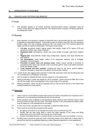
<strong>Major</strong> <strong>Hazard</strong> <strong>Standard</strong><strong>Underground</strong> <strong>Ground</strong> <strong>Control</strong>** Uncontrolled copy. Use latest revision **D Example of <strong>Ground</strong> ReinforcementInstallation Instructions(This accompanies the SWP for the specific supportor reinforcement type.)The process of installing ground reinforcementinvolves seven steps.The process is explained below. Each action includesat the start and end of that task the requirement toconduct a ground hazard identification, assessmentand take appropriate action.Step 1. Obtain the correct Work Plan.The plan may be specific to each excavation.Step 2. Assemble, and check the equipment andmaterials.The installation equipment required toachieve a quality installation to thespecification set out on the <strong>Ground</strong> <strong>Control</strong>Plan should be assembled. This equipmentshould be checked for safe operation, correctfunction, dimension and, if necessary,calibration.The required ground reinforcement (orcontrol) materials specified in the <strong>Ground</strong><strong>Control</strong> Plan must be assembled.Unacceptable variations should be rejected.Acceptable or unavoidable variations shouldbe recorded and input into the <strong>Ground</strong>Conditions Model.General criteria for inclusion into a checklistare given below in terms of the threedifferent generic types of rock bolt.Criteria for Friction Rock StabilisersGeometry: DiameterLengthTypeConditions: CorrosionDamageMaterials: Check tags and labelsCompatibility: Plates/elements.Criteria for Fully Grouted DevicesGeometry: DiameterLengthTypeThreads/nuts/washersPlateConditions: CorrosionDamageMaterials: Tags and labels checkAge and use by date ofcements and resinsPackagingCompatibility: Plates/elementsWashers and nutsExpansion shellsWater and cementResin and rock type.Criteria Point Anchored DevicesGeometry: DiameterLengthTypeThreads/nuts/washersPlateConditions: CorrosionDamageMaterials: Tags and labels checkAge and use by date of resinPackagingCompatibility: Plates/elementsWashers and nutsExpansion shell type andsize.Step 3. Drill the holes and/or prepare the surface.The holes for reinforcement must be drilledin the correct position, and be of the correctorientation and dimensions. For support ofshotcrete, mesh, etc., the surface may need tobe carefully cleaned down.SAF-MHS-01 Rev. 1 DOCS No. 55945 Issued: 19/06/00 Page 19 of 23
<strong>Major</strong> <strong>Hazard</strong> <strong>Standard</strong><strong>Underground</strong> <strong>Ground</strong> <strong>Control</strong>** Uncontrolled copy. Use latest revision **Step 4. Install the ground reinforcement.The ground reinforcement must be installedaccording the SWP for that groundreinforcement type, and any specialinstructions that might be required by the<strong>Ground</strong> <strong>Control</strong> Plan must be followed.Step 5. Make the final adjustment of groundreinforcement.The final adjustment or modification mayinclude post-tensioning, post-grouting,placing extra bolts to pin straps and mesh,application of curing sprays on shotcrete,etc. These tasks must be treated with thesame care as during the initial installationstage, and will often involve specialinstructions in the <strong>Ground</strong> <strong>Control</strong> Plan andin the SWP.Step 6. Check the installation and groundconditions.The <strong>Ground</strong> <strong>Control</strong> Operator must ensurethat the ground reinforcement has beeninstalled according to the <strong>Ground</strong> <strong>Control</strong>Plan, but has not (regardless of the Plan)inadvertently produced a hazardouscondition.Step 7. Record ground conditions and groundreinforcement conditions.It is important to record the groundconditions, the condition of the installedground reinforcement and any variations ordifficulties encountered during installation.This information is vital for the <strong>Ground</strong>Conditions Model. A record of no variationsor no difficulties is equally as important.Obtain correct planAssemble and checkmaterials and equipment<strong>Hazard</strong> identificationassessment and actionDrill holes and/orprepare surfaceInstall ground supportPretension or adjust asrequiredRecord conditionsand/or variationsCheck installation andground conditionsThe <strong>Ground</strong> <strong>Control</strong> Installation ProcessSAF-MHS-01 Rev. 1 DOCS No. 55945 Issued: 19/06/00 Page 20 of 23
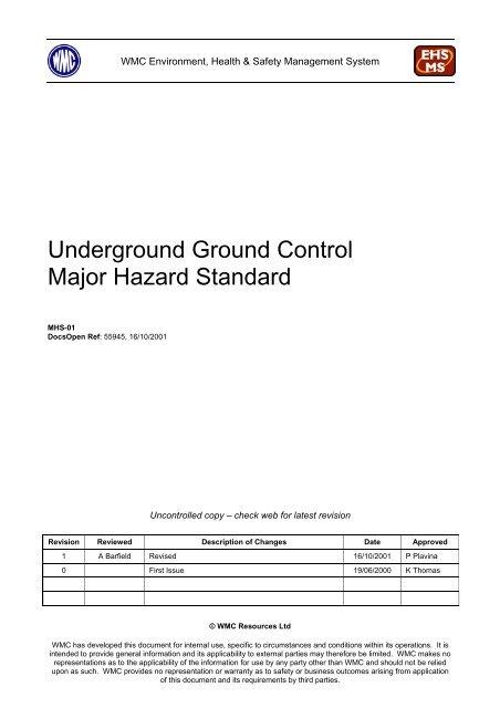
<strong>Major</strong> <strong>Hazard</strong> <strong>Standard</strong><strong>Underground</strong> <strong>Ground</strong> <strong>Control</strong>** Uncontrolled copy. Use latest revision **E Example of a <strong>Ground</strong> <strong>Hazard</strong> Identification and <strong>Control</strong> SystemThe <strong>Ground</strong> <strong>Hazard</strong> Identification and <strong>Control</strong>System involves a process of five basic steps. Theprocess is explained below.Step 1. Inspection Schedule.An inspection schedule must be set up forexcavations used for production andinfrastructure. The timetable for theinspections should be according to the riskand planning information.Step 2. Inspection, Identification and Assessment of<strong>Ground</strong> Conditions and <strong>Hazard</strong>s.The inspection should be conducted as perthe schedule. The person making theinspection should consider items general toall excavations and items specific to aparticular site. Some of these items are listedbelow and the features highlighted in boldare considered to be minimal features forwhich all personnel should have skills torecognise.<strong>Ground</strong> Conditions• Excessive stress conditions• Cracking, ticks and boots• Block shapes and sizes (hazardous shapeand size)• Structure (hazardous predisposition inrelation to excavation)• Pendants (partly bounded by joints orfractures)• Unravelling conditions• Squeeze and bulge conditions• Spalling and seismic conditions• Complex 3-D excavation shapes• Undercut walls and pillars• Sounding rock• Closure of joints and holes• Extrusion of joint fillings• Water from joints, holes, staining• Overbreak• ‘Dog ear’ overbreak in excavation corners• Arching• Buckling and kinking of layers• Blast percussion zones• Blast fractures• Partly stripped holes.<strong>Ground</strong> Reinforcement• Deformation of external fittings• Corrosion• Hung-up rock in mesh and mesh baskets• Shotcrete - hollow drumminess• Shotcrete - cracking, flaking• Sounding elements, plates and fittings• Hung-up blocks and scats• Twisting of strand devices• Seepage• Lüder lines on plates• Breaking of mesh welds• Yielding of wires of mesh• Tearing of mesh at bolts• Shotcrete - seepage• Shotcrete - discolouration• Shotcrete - leaching of salts.Step 3. Recording the <strong>Ground</strong> Condition <strong>Hazard</strong>s.A form that allows the easy recording ofconditions and variations should be preparedfor the site. The form should include thegeneral and specific list of points associatedwith the ground conditions at that site.Step 4. The <strong>Ground</strong> Condition <strong>Hazard</strong>s.The ground condition hazards must beproperly communicated, both by verbal andwritten communication depending on thehazard severity. The ground conditionhazards must also be permanently recordedin the <strong>Ground</strong> Conditions Model.Step 5. Tactical or Strategic Action.Strategic or tactical action, or both, may berequired for some conditions, depending onthe nature and severity of the situation.• Tactical action involves theimplementation of measures, usuallyphysical, to address the situation• Strategic action involves furtherinvestigation or research to decide on themost appropriate physical change toimplement.The process requires that the effect of the tacticalaction be continually monitored.SAF-MHS-01 Rev. 1 DOCS No. 55945 Issued: 19/06/00 Page 21 of 23
<strong>Major</strong> <strong>Hazard</strong> <strong>Standard</strong><strong>Underground</strong> <strong>Ground</strong> <strong>Control</strong>** Uncontrolled copy. Use latest revision **Inspection schedule forexcavationsInspection, identification &assessment of GC &hazardsGeneral &specific features<strong>Ground</strong>conditionsmodelRecording of GC &hazardsCommunication &reporting of potentialhazardsStrategic actionTactical actionThe <strong>Ground</strong> <strong>Hazard</strong> Identification and <strong>Control</strong>SystemSAF-MHS-01 Rev. 1 DOCS No. 55945 Issued: 19/06/00 Page 22 of 23