Underground Ground Control Major Hazard Standard - MIRMgate
Underground Ground Control Major Hazard Standard - MIRMgate
Underground Ground Control Major Hazard Standard - MIRMgate
Create successful ePaper yourself
Turn your PDF publications into a flip-book with our unique Google optimized e-Paper software.
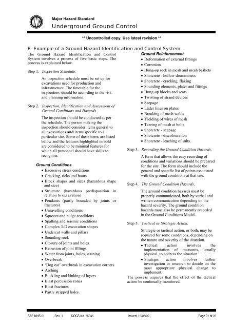
<strong>Major</strong> <strong>Hazard</strong> <strong>Standard</strong><strong>Underground</strong> <strong>Ground</strong> <strong>Control</strong>** Uncontrolled copy. Use latest revision **E Example of a <strong>Ground</strong> <strong>Hazard</strong> Identification and <strong>Control</strong> SystemThe <strong>Ground</strong> <strong>Hazard</strong> Identification and <strong>Control</strong>System involves a process of five basic steps. Theprocess is explained below.Step 1. Inspection Schedule.An inspection schedule must be set up forexcavations used for production andinfrastructure. The timetable for theinspections should be according to the riskand planning information.Step 2. Inspection, Identification and Assessment of<strong>Ground</strong> Conditions and <strong>Hazard</strong>s.The inspection should be conducted as perthe schedule. The person making theinspection should consider items general toall excavations and items specific to aparticular site. Some of these items are listedbelow and the features highlighted in boldare considered to be minimal features forwhich all personnel should have skills torecognise.<strong>Ground</strong> Conditions• Excessive stress conditions• Cracking, ticks and boots• Block shapes and sizes (hazardous shapeand size)• Structure (hazardous predisposition inrelation to excavation)• Pendants (partly bounded by joints orfractures)• Unravelling conditions• Squeeze and bulge conditions• Spalling and seismic conditions• Complex 3-D excavation shapes• Undercut walls and pillars• Sounding rock• Closure of joints and holes• Extrusion of joint fillings• Water from joints, holes, staining• Overbreak• ‘Dog ear’ overbreak in excavation corners• Arching• Buckling and kinking of layers• Blast percussion zones• Blast fractures• Partly stripped holes.<strong>Ground</strong> Reinforcement• Deformation of external fittings• Corrosion• Hung-up rock in mesh and mesh baskets• Shotcrete - hollow drumminess• Shotcrete - cracking, flaking• Sounding elements, plates and fittings• Hung-up blocks and scats• Twisting of strand devices• Seepage• Lüder lines on plates• Breaking of mesh welds• Yielding of wires of mesh• Tearing of mesh at bolts• Shotcrete - seepage• Shotcrete - discolouration• Shotcrete - leaching of salts.Step 3. Recording the <strong>Ground</strong> Condition <strong>Hazard</strong>s.A form that allows the easy recording ofconditions and variations should be preparedfor the site. The form should include thegeneral and specific list of points associatedwith the ground conditions at that site.Step 4. The <strong>Ground</strong> Condition <strong>Hazard</strong>s.The ground condition hazards must beproperly communicated, both by verbal andwritten communication depending on thehazard severity. The ground conditionhazards must also be permanently recordedin the <strong>Ground</strong> Conditions Model.Step 5. Tactical or Strategic Action.Strategic or tactical action, or both, may berequired for some conditions, depending onthe nature and severity of the situation.• Tactical action involves theimplementation of measures, usuallyphysical, to address the situation• Strategic action involves furtherinvestigation or research to decide on themost appropriate physical change toimplement.The process requires that the effect of the tacticalaction be continually monitored.SAF-MHS-01 Rev. 1 DOCS No. 55945 Issued: 19/06/00 Page 21 of 23


