electronic digital beamforming implementation for radars
electronic digital beamforming implementation for radars
electronic digital beamforming implementation for radars

You also want an ePaper? Increase the reach of your titles
YUMPU automatically turns print PDFs into web optimized ePapers that Google loves.
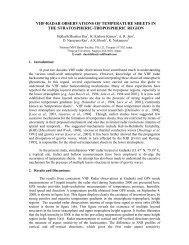
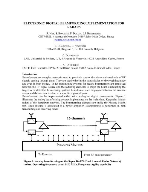
ELECTRONIC DIGITAL BEAMFORMING IMPLEMENTATION FORRADARSR. NEY, S. BONAIMÉ, F. DOLON , J.J. BERTHELIER,CETP/IPSL, 4 Avenue de Neptune, 94107 Saint-Maur Cedex, Francerichard.ney@cetp.ipsl.frR. CLAIRQUIN, D. NEVEJANSBIRA/IASB, Ringlaan 3, B-1180 Brussels, BelgiumC. DUVANAUDLAII, Université de Poitiers, IUT, 4 Avenue de Varsovie, 16021 Angoulême Cedex, FranceA. D’HERMIESESIEE, Cité Descartes, BP 99, 2 Bld Blaise Pascal, 93162 Noisy-le-Grand Cedex, FranceIntroduction.Beam<strong>for</strong>mers are complex networks used to precisely control the phase and amplitude of RFsignals passing through them. They are used either in the transmission or the receiving modeand even in both modes. In RF transmitting systems <strong>for</strong> <strong>radars</strong>, beam<strong>for</strong>mers are employedbetween the RF signal source and the radiating elements to shape the beam illuminating thetarget to be detected. In receiving systems beam<strong>for</strong>mers are employed between the antennaarrays and the receiver to observe a specific region of space.Beam<strong>for</strong>mers can be implemented either with analog or <strong>digital</strong> components. Figure 1illustrates the analog <strong>beam<strong>for</strong>ming</strong> concept implemented on the Iceland and Kerguelen islands<strong>radars</strong> of the SuperDarn network. The <strong>beam<strong>for</strong>ming</strong> elements are inside the Phasing Matrixbox. Each antenna is associated to a power amplifier. Beam<strong>for</strong>ming is per<strong>for</strong>med in bothtransmitting and receiving mode.16 channelsPHASING MATRIXTo ReceiverFrom RF pulse generatorFigure 1: Analog <strong>beam<strong>for</strong>ming</strong> on the Super DARN (Dual Auroral Radar Network)<strong>radars</strong>. Operating frequency band: 8-20 MHz, Frequency Agility capability
The main element of the unit (figure 3) is a FPGA programmed in VHDL language whichper<strong>for</strong>ms the <strong>digital</strong> wave generation through a DDS scheme, the full control of the radaroperation and interface with a PC and the coherent integrations (up to 2 24 ) of 2500 range gatessignals. The frequency range is 0.2 to 5 MHz and the output peak power is 10W. The receiveris a standard analog unit. For the field tests, the ON/OFF, the data transfer, the controlparameters of the radar, are achieved through a wireless link between the PC and the radar.The data transfer is done according to a MIL STD 1553-like protocol.A <strong>digital</strong> <strong>beam<strong>for</strong>ming</strong> <strong>implementation</strong>.Figure 4 illustrates the concept.Each antenna of an antenna network has to be associated to an <strong>electronic</strong> unit. Thisarchitecture is very flexible and allows Digital Beam<strong>for</strong>ming <strong>for</strong> both transmission andreception, or if desired <strong>for</strong> reception only.This hardware can be applied to many <strong>radars</strong> in the HF and VHF bands. The analog receivercan be replaced by a <strong>digital</strong> receiver which implements the ADC at the HF or VHF level,<strong>digital</strong> demodulation and matched filtering on the I and Q baseband signals.Conclusions.The radar unit developed at CETP allows:• Digital <strong>beam<strong>for</strong>ming</strong> in the receiving and transmitting modes.• A great number of range gates, a great flexibility (frequency generation, ability tooversampling, large range values <strong>for</strong> parameters…).• The VHDL program can be implemented in any FPGA.• Practical user interface.• Medium cost.• Extension to VHF frequency range, to higher transmitted power.• Use of <strong>digital</strong> receiver (better per<strong>for</strong>mances and flexibility).These features are likely to promote the use of <strong>digital</strong> <strong>beam<strong>for</strong>ming</strong> at MF, HF, VHFfrequencies in several fields such as ionospheric <strong>radars</strong>, ST <strong>radars</strong>, oceanographic <strong>radars</strong>…References.Barton, P., (1980). Digital beam <strong>for</strong>ming <strong>for</strong> radar. IEE Proceedings, Vol. 127, Pt. F, N°4,August, pp. 266-277.Berthelier,J.J., R. Ney, V. Ciarletti, A. Reineix, B. Martinat, M. Hamelin, F. Costard, W.Kofman, P. Paillou, C. Duvanaud, D. Nevejans, W. Kofman, J.G. Trotignon, G. Grandjean,M. Zamora and A. Nagy (2003). GPR, A Ground Penetrating Radar <strong>for</strong> the NetLandermission. J. Geophys. Res., 108, ( E4), 8027.Ney, R, J.J. Berthelier, V. Ciarletti, B. Martinat, M. Hamelin, M. Rodriguez-Cassola, F.Dolon, S. Bonaimé, A. Reineix, D. Nevejans, C. Duvanaud, F. Costard, and P. Paillou(2002). The Ground Penetrating Radar of the Netlander Misssion. Proceedings of the NinthInternational Conference on Ground Penetrating Radar, University of Cali<strong>for</strong>nia, SantaBarbara, USA, Apil 29 – May 2, pp. 541-5 46.Steyskal, H. (1987). Digital Beam<strong>for</strong>ming Antennas. Microwave Journal, January 1987, pp.107-124.
DDSFrequency Range : 0 - 25MHzPulse ModulationCW, Bi - phase, BPSKDACPowerAmplifierF0FPGA0Radar Controlπ/ 2ReceiverDemodulation at FoCoherent Integration sADCADCAcess-point PCMCIAWireless 802.11bFigure 3 : The NetLander GPR radar architectureRADAR-1Wireless802.11bRADAR-2RADAR-NFigure 4: Example of a <strong>digital</strong> <strong>beam<strong>for</strong>ming</strong> radar architecture