ON THE RADIATION EFFICIENCY OF COCO ANTENNAS
ON THE RADIATION EFFICIENCY OF COCO ANTENNAS
ON THE RADIATION EFFICIENCY OF COCO ANTENNAS
- No tags were found...

Create successful ePaper yourself
Turn your PDF publications into a flip-book with our unique Google optimized e-Paper software.
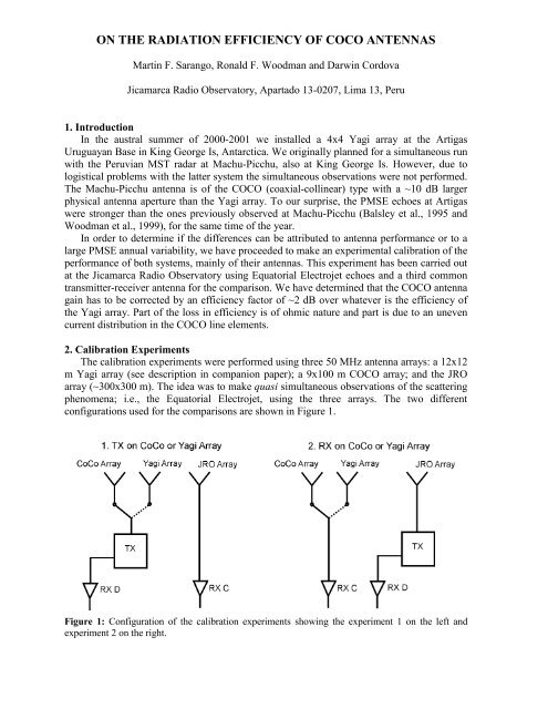
<strong>ON</strong> <strong>THE</strong> RADIATI<strong>ON</strong> <strong>EFFICIENCY</strong> <strong>OF</strong> <strong>COCO</strong> <strong>ANTENNAS</strong>Martin F. Sarango, Ronald F. Woodman and Darwin CordovaJicamarca Radio Observatory, Apartado 13-0207, Lima 13, Peru1. IntroductionIn the austral summer of 2000-2001 we installed a 4x4 Yagi array at the ArtigasUruguayan Base in King George Is, Antarctica. We originally planned for a simultaneous runwith the Peruvian MST radar at Machu-Picchu, also at King George Is. However, due tologistical problems with the latter system the simultaneous observations were not performed.The Machu-Picchu antenna is of the <strong>COCO</strong> (coaxial-collinear) type with a ~10 dB largerphysical antenna aperture than the Yagi array. To our surprise, the PMSE echoes at Artigaswere stronger than the ones previously observed at Machu-Picchu (Balsley et al., 1995 andWoodman et al., 1999), for the same time of the year.In order to determine if the differences can be attributed to antenna performance or to alarge PMSE annual variability, we have proceeded to make an experimental calibration of theperformance of both systems, mainly of their antennas. This experiment has been carried outat the Jicamarca Radio Observatory using Equatorial Electrojet echoes and a third commontransmitter-receiver antenna for the comparison. We have determined that the <strong>COCO</strong> antennagain has to be corrected by an efficiency factor of ~2 dB over whatever is the efficiency ofthe Yagi array. Part of the loss in efficiency is of ohmic nature and part is due to an unevencurrent distribution in the <strong>COCO</strong> line elements.2. Calibration ExperimentsThe calibration experiments were performed using three 50 MHz antenna arrays: a 12x12m Yagi array (see description in companion paper); a 9x100 m <strong>COCO</strong> array; and the JROarray (~300x300 m). The idea was to make quasi simultaneous observations of the scatteringphenomena; i.e., the Equatorial Electrojet, using the three arrays. The two differentconfigurations used for the comparisons are shown in Figure 1.Figure 1: Configuration of the calibration experiments showing the experiment 1 on the left andexperiment 2 on the right.
We have taken advantage of the narrow beam of the Jicamarca antenna. For experiment 1it is essentially probing the field transmitted by the two antennas under calibration at thepoint of maximum gain. For experiment 2, it is effectively placing a point source at the centerof the receiving antennas under calibration (the North-South dimension is reduced furtherbecause the aspect sensitivity.)Experiment 1: Transmission on <strong>COCO</strong> and Yagi ArraysIn the first configuration/experiment the transmission is alternated between the <strong>COCO</strong>and Yagi arrays, while the JRO array is used for receiving (RXC). This configuration allowsevaluating the transmission efficiency of the arrays under calibration. The signals at RXDcorrespond to the radar case that we will not analyze in this paper.Experiment 2: Reception on <strong>COCO</strong> and Yagi ArraysThe second configuration/experiment allows evaluating the receiving efficiency of thetwo arrays. As shown in Figure 1, the JRO array is used for transmission and the <strong>COCO</strong> andYagi arrays are alternated for reception (RXC).An artist representation of the beam-widths and the corresponding pointing directionswith respect to the perpendicular to B for the three antenna arrays are shown in Figure 2. Theelements/lines of the Yagi/<strong>COCO</strong> arrays are oriented in the North-South magnetic direction(Y). The longest dimension of the <strong>COCO</strong> array (100m) also corresponds to the Y direction.The effective antenna dimensions, including the effective radius of the cross section of thearray elements, for the <strong>COCO</strong> and Yagi arrays are shown in Table 1.Figure 2: Artist representation of the antenna beam-widths and the corresponding pointing directionswith respect to the perpendicular to B.Table 1: <strong>COCO</strong> and Yagi antenna array dimensions (including the effective radius of thecross section of the array elements)Antenna array East-West dimension(X)North-South dimension(Y)Antenna Area[m 2 ]<strong>COCO</strong> Array L C,X = 12.0m L C,Y = 100m A C = 1200.00Yagi Array L Y,X = 15.0m L Y,Y = 15.0m A Y = 225.003. Experiment ResultsSeveral calibration experiments have been performed after the 2000-2001 Antarcticcampaign. The results presented and discussed here correspond to data gathered in December1 st , 2003.
The signal power ratios, S C /S Y , for the experiments 1 and 2 are shown in Tables 2 and 3respectively.Table 2: Experiment 1 results, Transmission on <strong>COCO</strong> and Yagi ArraysRX Antenna Array S C /S Y (SNR, dB) S C /S Y (Total Power, dB)<strong>COCO</strong> / Yagi (RXD) 13.9237 11.1051JRO (RXC) 5.4195 5.6255Table 3: Experiment 2 results, Transmission on JRO ArrayRX Antenna Array S C /S Y (SNR, dB) S C /S Y (Total Power, dB)<strong>COCO</strong> / Yagi (RXC) 5.9739 5.5257Using the “one way” signal power ratios shown in tables 2 and 3 we can calculate theefficiency ratio between the <strong>COCO</strong> and Yagi Arrays. If we consider two antenna arrays, withareas A C and A Y and efficiencies ε C and ε Y , the ratio of signal power S C /S Y is given by:SSCYG'G'C= (1)Ywhere S is power, and G’ is the effective gain. The antenna gain, G, for an ideal antenna isproportional to its area; i.e., G = Ly x Lx. Ly and Lx are the dimensions of the antenna,including the effective radius of the cross section of the array elements (see Table 1). Theeffective gain G’ is corrected by an efficiency factor (ε), that takes into account theillumination efficiency of the area (ε B ); and any Ohmic loss (ε Ω ).Then, we can write,G' Gε= kAεB ε = kAε(2)= ΩSSCY⎛ εCG=⎜⎝ εYGCY⎞ ⎛ εCA⎟ =⎜⎠ ⎝ εYACY⎞⎟⎠(3)and then,SSCY⎛ ε ⎞⎛LC= ⎜⎜⎟⎝ εY ⎠⎝LC,XY , XLLC , YY , Y⎞⎟⎠(4)⎡⎛ε ⎞⎤⎡CS⎢⎜⎟⎥= ⎢⎣⎝εY⎠⎦⎣ SCY⎤ ⎡⎛L⎥ − ⎢⎜⎦ ⎢⎣⎝ LC,YY , YLLC,XY , X⎞⎤⎟⎥⎠⎥⎦(5)where the [] operator denotes 10*Log10 operation. The Total Power ratios for RXC in table 2correspond to Transmission with the <strong>COCO</strong> and Yagi Arrays; i.e., one way case. Theexperimental total power ratio in the receiving antenna, [S C /S Y ] , was 5.6255 dB, which weshould correct for the insertion loss difference of the main feeding cables by -0.5 dB. Thearea ratio, [A C /A Y ], from table 1 is 7.27 dB. Therefore we have an efficiency ratio ontransmission, [ε C /ε Y ] T , of -2.1445 dB.
We can also calculate the efficiency ratio on reception, [ε C /ε Y ] R , using expression (5) andthe experimental values in table 3. We obtain an efficiency ratio on reception of -2.2443dB,which is reassuring since it differs by 0.0998 dB from the figure obtained in experiment 1.4. Conclusions- The special characteristics of the Jicamarca antenna array; i.e., its very narrow beam, hasallowed probing the field transmitted by the <strong>COCO</strong> and Yagi antennas at the point ofmaximum gain. It has also been used to place a point source at the center of the antennasunder calibration.- The results for the Transmission and Reception experiments conform very well, asexpected. The 0.0988 dB difference between experiments 1 and 2 can be attributed toexperimental errors.- We have found that the 100m <strong>COCO</strong> antenna gain has to be corrected by an efficiencyfactor of ~2.2 dB over whatever is the efficiency of the 3-element Yagi array. Therefore,assuming that the Yagi array is lossless, the gain of a 100m <strong>COCO</strong> antenna has to becorrected by an efficiency factor of ~2.2 dB.Acknowledgments: The VHF radar at the Peruvian Antarctic Station “Machu-Picchu” is animportant part of the Peruvian research activities in Antarctica. The 100m <strong>COCO</strong> lines forthese experiments were provided by the Physics Lab of the University of Piura, Peru. Wewould like to acknowledge the support received from the Jicamarca Radio Observatory staff.ReferencesBalsley, B.B., R.F. Woodman, M. Sarango, R. Rodriguez, J. Urbina, E. Ragaini, J. Carey, M.Huaman, and A. Giraldez, On the lack of southern hemisphere polar mesospheresummer echoes, J. Geophys. Res., 100(D6), 11685-11693, 1995Woodman, R.F., B.B. Balsley, F. Aquino, L. Flores, E. Vasquez, M. Sarango, M. Huaman,and H. Soldi, First observations of polar mesosphere summer echoes in Antarctica, J.Geophys. Res., 104(A10), 22577-22590, 1999