ON THE RADIATION EFFICIENCY OF COCO ANTENNAS
ON THE RADIATION EFFICIENCY OF COCO ANTENNAS
ON THE RADIATION EFFICIENCY OF COCO ANTENNAS
- No tags were found...

You also want an ePaper? Increase the reach of your titles
YUMPU automatically turns print PDFs into web optimized ePapers that Google loves.
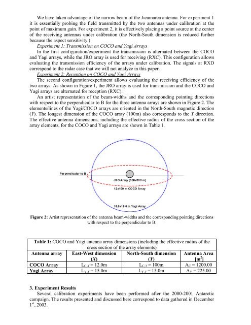
We have taken advantage of the narrow beam of the Jicamarca antenna. For experiment 1it is essentially probing the field transmitted by the two antennas under calibration at thepoint of maximum gain. For experiment 2, it is effectively placing a point source at the centerof the receiving antennas under calibration (the North-South dimension is reduced furtherbecause the aspect sensitivity.)Experiment 1: Transmission on <strong>COCO</strong> and Yagi ArraysIn the first configuration/experiment the transmission is alternated between the <strong>COCO</strong>and Yagi arrays, while the JRO array is used for receiving (RXC). This configuration allowsevaluating the transmission efficiency of the arrays under calibration. The signals at RXDcorrespond to the radar case that we will not analyze in this paper.Experiment 2: Reception on <strong>COCO</strong> and Yagi ArraysThe second configuration/experiment allows evaluating the receiving efficiency of thetwo arrays. As shown in Figure 1, the JRO array is used for transmission and the <strong>COCO</strong> andYagi arrays are alternated for reception (RXC).An artist representation of the beam-widths and the corresponding pointing directionswith respect to the perpendicular to B for the three antenna arrays are shown in Figure 2. Theelements/lines of the Yagi/<strong>COCO</strong> arrays are oriented in the North-South magnetic direction(Y). The longest dimension of the <strong>COCO</strong> array (100m) also corresponds to the Y direction.The effective antenna dimensions, including the effective radius of the cross section of thearray elements, for the <strong>COCO</strong> and Yagi arrays are shown in Table 1.Figure 2: Artist representation of the antenna beam-widths and the corresponding pointing directionswith respect to the perpendicular to B.Table 1: <strong>COCO</strong> and Yagi antenna array dimensions (including the effective radius of thecross section of the array elements)Antenna array East-West dimension(X)North-South dimension(Y)Antenna Area[m 2 ]<strong>COCO</strong> Array L C,X = 12.0m L C,Y = 100m A C = 1200.00Yagi Array L Y,X = 15.0m L Y,Y = 15.0m A Y = 225.003. Experiment ResultsSeveral calibration experiments have been performed after the 2000-2001 Antarcticcampaign. The results presented and discussed here correspond to data gathered in December1 st , 2003.