Arc Protection Relay REA 10_ - APE Distribuidor ABB
Arc Protection Relay REA 10_ - APE Distribuidor ABB
Arc Protection Relay REA 10_ - APE Distribuidor ABB

Create successful ePaper yourself
Turn your PDF publications into a flip-book with our unique Google optimized e-Paper software.
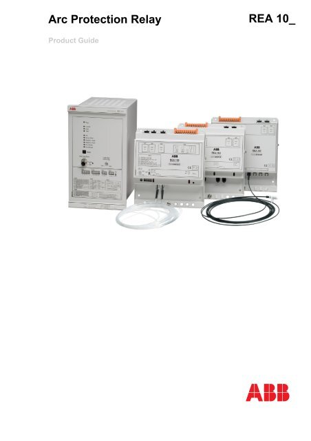
<strong>Arc</strong> <strong>Protection</strong> <strong>Relay</strong><strong>REA</strong> <strong>10</strong>_Product Guide
<strong>Arc</strong> <strong>Protection</strong> <strong>Relay</strong> <strong>REA</strong> <strong>10</strong>_1MRS750929-MBGIssued: 1May 1999Status: UpdatedVersion: D / 22.06.2005Data subject to change without noticeFeatures • Loop-type sensor fiber, radial sensor fiberor lens-type sensor for arc detection• Two high-speed semiconductor outputs fortripping• Tripping from light only or secured withfast, adjustable three-phase or two-phaseand neutral overcurrent condition• Total operate time
<strong>Arc</strong> <strong>Protection</strong> <strong>Relay</strong> <strong>REA</strong> <strong>10</strong>_1MRS750929-MBGDesign <strong>Arc</strong> protection relay <strong>REA</strong> <strong>10</strong>1Overcurrent detection unitThe selection switch is used to select betweenthree-phase current measurement or twophaseand neutral current measurement.Three-phase current measurementThe three-phase currents are measured viatransformers. When the current on one phaseexceeds the selected reference level, an overcurrentsignal is activated.The selection switch is used to select the currentreference level for the current inputs L1,L2 and L3. The available current level settingsare 0.5, 1.0, 1.5, 2.5, 3.0, 5.0 and 6.0times the rated current (In = 1.0 A or 5.0 A).Two-phase and neutral current measurementWhen the current in L1, L3 or L2 (neutralcurrent) exceeds the selected reference level,an overcurrent signal is activated.The available current level settings for L1 andL3 are 0.5, 1.0, 1.5, 2.5, 3.0, 5.0 and 6.0 timesthe rated current (In = 1.0 A or 5.0 A).The available current level settings for L2 are0.05, 0.1, 0.15, 0.25, 0.3, 0.5 and 0.6 timesthe rated current (In = 1.0 A or 5.0 A).Light detection unitThe light captured by the sensor is amplifiedand compared to the pre-selected light referencelevel. Once the light exceeds the set referencelevel, a light signal is activated.The selection switch is used to activate thearc detection sensor.The selection switch is used to select automaticor manual light reference level.If the automatic reference level is selected,the unit forms the reference level based onthe backlight intensity measured by the sensor.When the manual reference level is selected,the unit forms the reference level based onthe value that was selected with the light referencelevel adjustment potentiometer on thefront panel.The sensor fiber condition is monitored bysending a test pulse through the fiber. If a testpulse is not received at regular intervals at theother end of the fiber loop, the “Sensor Fault”LED and the self-supervision LED “IRF” areactivated, and the IRF relay resets.If the sensor-monitoring feature is notneeded, it can be deactivated by using theselection switch.Sensitivity of sensorsFig. 1A050616Sensitivity of <strong>REA</strong> <strong>10</strong>_ sensors at variousbacklight compensation settingsThe intensity of a high-current arc light in atwo- or three-phase short circuit can be tensof thousands of luxes. The intensity of a normaloffice lighting is 200-300 luxes.The exact determination of the detectingreach of the light sensors is difficult, becausethe detecting reach depends on several factors:• Light source energy• Fiber length• Reflectances• Backlight compensation settingsSensitivity of fiber sensorsThe incidence angle of the light is not relevantwith fiber sensors.When an arc protection system is designed,the length of the sensor fiber per one switchgearcompartment must be selected accordingto the possible short-circuit or earth-fault current,and the distance between the sensor andarc. When selecting sensor fiber length, referto the table 1.4
<strong>Arc</strong> <strong>Protection</strong> <strong>Relay</strong> <strong>REA</strong> <strong>10</strong>_1MRS750929-MBG.Table 1: Minimum length (cm) of the exposed sensor fiber per one switchgearcompartmentFault current (rms)Distance between sensor and arc<strong>10</strong>0 cm 200 cm 300 cm 400 cm0.5 kA 20 - a - a - a0.7 kA 20 70 2<strong>10</strong> 2801.4 kA 20 20 20 1402.2 kA 20 20 20 20The information in the table 1 is based on thefollowing reference conditions:• Copper busbars• <strong>Arc</strong> length <strong>10</strong> cm• Surrounding light ~ 400 lux• No reflecting surfaces• Light reference level is set one scale markto the right from the minimumSensitivity of lens sensorsThe relative sensitivity of the lens sensorfrom different angles of lightning is presentedin figure 2. The normal operating sector is -130°... +130°. In practice, light is alsoreflected from the compartment walls, so thedetecting angle is not critical.The detection distance of a lens sensor is 3meters. Therefore, when protecting busbarsections, the maximum distance of lens sensorsfrom one another is 6 meters.Fig. 2a) Not operational.SensitivityAnglesRelative sensitivity of the <strong>REA</strong> lens sensorfrom different angles of lightingTrip outputThe trip output is provided with:• Two high-speed galvanically isolatedIGBT semi-conductor outputs, HSO1 andHSO2• <strong>Relay</strong> output, TRIP3The control signal of the outputs is activatedif the overcurrent signal and the light signal,but not the operating voltage fault signal, areactive at the same time.When the “Trip Condition” key switch on therelay’s front panel is in “Light” position, theovercurrent signal is constantly active, andtripping is activated by an arc alone. When atrip signal is delivered, the trip outputs arelatched in active state. The outputs can bereseted either by pushing the “Reset” buttonon the relay’s front panel, or by using a resetsignal applied to RESET input.Ports A and B for connecting extensionunitsThe selection switches are used to activate theports A and B.The extension units are connected to the portsA and B by using connection cables. Theextension unit receives its operating voltageand operation signals over the port.The ports are protected against short-circuitand cable breaks. If the connection cablefrom a port breaks, the concerned chain isdisconnected, and the fault LED (Port AFault” or “Port B Fault”) as well as the “IRF”LED on the central unit are lit, and the IRFrelay resets.A maximum of 5 extension units can be connectedto one port. If an extension unitincluded in the chain connected to the port isdamaged, the fault LED of the port startsflashing, the “IRF” LED is lit and the IRFrelay resets.5
<strong>Arc</strong> <strong>Protection</strong> <strong>Relay</strong> <strong>REA</strong> <strong>10</strong>_1MRS750929-MBGOptolink communicationThe <strong>REA</strong> <strong>10</strong>1 relay contains two communicationlinks: Optolink 1 and Optolink 2.The selection switches are used to select thelinks to be used, and the messages to be communicatedbetween them.The purpose of thecommunication link is to communicateON/OFF type messages between the centralunits over the signal transfer fiber. The messagecan be:• Light signal• Overcurrent signal• Trip signalOnly one type of message per optolink can betransmitted between the central units. Thedata to be communicated depends on the systemdesign.To monitor the connection, a test pulse is sentthrough the signal transfer fiber at regularintervals. If the test pulse is not received atthe specified time, the optolink fault LED(“Optolink 1 Fault” or “Optolink 2 Fault”)and the “IRF” LED of the central unit is lit,and the IRF relay resets.Circuit-breaker failure protectionThe circuit-breaker failure protection (CBFP)is enabled, when the Trip Condition keyswitch is in “Current&Light” position.The circuit-breaker failure protection isimplemented by delaying either the HSO2output or the TRIP3 output, or when required,both the outputs. Note that if both the outputsare used, the delay time is the same, but thepick-up time of the relay (5...15 ms) is addedto the TRIP3 relay.The selection switches are used to select thewanted alternative.The selected delay time, <strong>10</strong>0 ms or 150 ms,starts running once the HSO1 is activated.Delayed tripping does not take place if theovercurrent signal disappears before the specifiedtime delay elapses.When the circuit-breaker failure protection isnot in use, all the trip outputs operate in parallel.Self-supervision unitIn addition to that mentioned in the abovesections, the self-supervision unit (IRF) monitorsthe operating voltage of the relay. If afault is detected in the operating voltages, theself-supervision unit prevents the relay fromoperating. In addition, the “IRF” LED of thecentral unit is lit, and the IRF relay resets.The self-supervision signal output operateson the closed circuit principle as presented inthe figure below. Under normal conditions,the output relay is energized and the contactgap between 8 and <strong>10</strong> is closed. If the auxiliarypower supply fails, or an internal fault isdetected, the contact gap between 8 and <strong>10</strong> isopened.IRFFig. 3Self-supervision output (IRF)<strong>10</strong>A050349Extension unit <strong>REA</strong> <strong>10</strong>3The <strong>Arc</strong> <strong>Protection</strong> Module <strong>REA</strong> <strong>10</strong>3 is anextension unit designed to be used togetherwith the central unit <strong>REA</strong> <strong>10</strong>1.The function of the <strong>REA</strong> <strong>10</strong>3 unit is to detectlight and to provide the <strong>REA</strong> <strong>10</strong>1 relay withinformation about this.The use of the extension unit allows the protectionarea to be extended and the protectedobject to be divided into smaller areasFeatures:Normal condition89<strong>10</strong>• Two sensor fibers for arc detection; loop orradial arrangement• Two signal relays for each sensor fiber• <strong>Relay</strong>s activated by light detected by thesensor fiber• Two RJ-45 ports for connecting <strong>REA</strong> <strong>10</strong>1relay and extension units• Self-supervision unit monitoring operatingvoltages and sensor fiber loops.Extension unit <strong>REA</strong> <strong>10</strong>5The <strong>Arc</strong> <strong>Protection</strong> Module <strong>REA</strong> <strong>10</strong>5 is anextension unit designed to be used togetherwith the central unit <strong>REA</strong> <strong>10</strong>1.IRFFault conditionThe function of the <strong>REA</strong> <strong>10</strong>5 unit is to detectlight and to carry out tripping, if the <strong>REA</strong> <strong>10</strong>1relay provides an overcurrent signal at thesame time, or delivers a trip command.The use of extension units allows the protectionarea to be extended and the protectedobject to be divided into smaller areas. Thus amore selective system is obtained.896
<strong>Arc</strong> <strong>Protection</strong> <strong>Relay</strong> <strong>REA</strong> <strong>10</strong>_1MRS750929-MBGFeatures:• Loop-type or radial sensor fiber for arcdetection.• Two high-speed semi-conductor outputsfor tripping.• Signal relay activated by light detected bythe sensor fiber.• Three RJ-45 ports for connecting the<strong>REA</strong> <strong>10</strong>1 relay and extension units.• Circuit-breaker failure protection. Delayedlight signal to <strong>REA</strong> <strong>10</strong>1, which opens thehigher-level circuit breaker.• Self-supervision unit which monitors operatingvoltages and the sensor fiber loop.Extension unit <strong>REA</strong> <strong>10</strong>7The <strong>Arc</strong> <strong>Protection</strong> Module <strong>REA</strong> <strong>10</strong>7 is anextension unit designed to be used togetherwith the central unit, <strong>Arc</strong> <strong>Protection</strong> <strong>Relay</strong><strong>REA</strong> <strong>10</strong>1.The function of the <strong>REA</strong> <strong>10</strong>7 unit is to detectlight and to provide the <strong>REA</strong> <strong>10</strong>1 relay withinformation about this.The use of the extension unit allows the protectionarea to be extended and the protectedobject to be divided into smaller areas.Features:• 8 lens-type sensors for arc detection• 2 signal relays• 2 RJ-45 ports for connecting <strong>REA</strong> <strong>10</strong>1relay and other extension units• Self-supervision unit that monitors operatingvoltages• LED indicators for each sensor.7
<strong>Arc</strong> <strong>Protection</strong> <strong>Relay</strong> <strong>REA</strong> <strong>10</strong>_1MRS750929-MBGTechnical dataTable 2: Current inputRated currentContinuous load currentMomentary current for 1 sDynamic current withstand, half-wave valueInput impedanceRated frequency1 A / 5 A4 A / 20 A<strong>10</strong>0 A / 500 A250 A/ 1250 A
<strong>Arc</strong> <strong>Protection</strong> <strong>Relay</strong> <strong>REA</strong> <strong>10</strong>_1MRS750929-MBGTable 6: Power supply<strong>Relay</strong> types <strong>REA</strong><strong>10</strong>1-AAA, <strong>REA</strong><strong>10</strong>1-AAAG:U aux ratedU aux variation<strong>Relay</strong> types <strong>REA</strong><strong>10</strong>1-CAA, <strong>REA</strong><strong>10</strong>1-CAAG:U aux ratedU aux variationTable 7: Power consumption<strong>REA</strong> <strong>10</strong>1<strong>REA</strong> <strong>10</strong>3(operating voltage over the port of<strong>REA</strong> <strong>10</strong>1)<strong>REA</strong> <strong>10</strong>5(operating voltage over the port of<strong>REA</strong> <strong>10</strong>1)<strong>REA</strong> <strong>10</strong>7(operating voltage over the port of<strong>REA</strong> <strong>10</strong>1)Power consumption of relay underquiescent/operating conditionsMax. port output powerMax. number of extensionunits/portMax. power consumption with <strong>10</strong>extension units connectedPower consumption of relay underquiescent/operating conditionsPower consumption of relay underquiescent/operating conditionsPower consumption of relay underquiescent/operating conditionsU r = 1<strong>10</strong>/120/220/240 V ACU r = 1<strong>10</strong>/125/220/250 V DC85...1<strong>10</strong>% U r (AC)80...120% U r (DC)U r = 24/48/60 V DC80...120% U r DC~9 W / ~12 W~19 W5
<strong>Arc</strong> <strong>Protection</strong> <strong>Relay</strong> <strong>REA</strong> <strong>10</strong>_1MRS750929-MBGTable 13: Environmental testsSpecified service temperature range-<strong>10</strong>...+55°CTransport and storage temperature range-40...+70°COperation in dry heat conditions According to IEC 60068-2-2Operation in dry cold conditions According to IEC 60068-2-1Damp heat test cyclic According to IEC 60068-2-30r.h. >95%, t = 20...55°CStorage temperature test According to IEC 60068-2-48Table 14: Encapsulation<strong>REA</strong> <strong>10</strong>1 Degree of protection, IEC 60529 IP 20Weightabout 4.6 kg<strong>REA</strong> <strong>10</strong>3 Degree of protection, IEC 60529 IP 20Weightabout 1.1 kg<strong>REA</strong> <strong>10</strong>5 Degree of protection, IEC 60529 IP 20Weightabout 1.1 kg<strong>REA</strong> <strong>10</strong>7 Degree of protection, IEC 60529 IP 20Weightabout 1.0 kgTable 15: Insulation testsDielectric tests according to IEC 60255-5Impulse voltage test according to IEC 60255-5Insulation resistance according to IEC 60255-52 kV, 50 Hz, 1 min.5 kV, 1.2/50 µs, 0.5 J><strong>10</strong>0 MΩ, 500 V DCTable 16: Electromagnetic compatibility testsEMC immunity test level meets the requirements listed below:1 MHz burst disturbance test according to IEC 60255-22-1, class III:Common modeDifferential modeElectrostatic discharge test according to IEC 6<strong>10</strong>00-4-2, class IV andANSI/IEEE C37.90.3-200:For contact dischargeFor air discharge2.5 kV1 kV8 kV15 kVRadio-frequency electromagnetic field disturbance test according to IEC 6<strong>10</strong>00-4-3 andIEC 60255-22-3:Amplitude-modulated:Frequency fField strength EPulse-modulated:Frequency fField strength ERadio frequency disturbance test according toIEC 6<strong>10</strong>00-4-6 and IEC 60255-22-6:Conducted, common modeFast transient disturbance tests according toIEC 60255-22-4 and IEC 6<strong>10</strong>00-4-4Surge immunity test according to IEC 6<strong>10</strong>00-4-5 and IEC 60255-22-5:Aux. voltage input, trip outputs:Line-to-lineLine-to-earthSignal contacts (IRF), current inputs, RESET input:Line-to-lineLine-to-earthElectromagnetic emission tests according to EN 55011 and IEC 60255-25:80...<strong>10</strong>00 MHz<strong>10</strong> V/m (rms)900 MHz<strong>10</strong> V/m (rms)<strong>10</strong> V, 150 kHz...80 MHz4 kV2 kV4 kV1 kV2 kV<strong>10</strong>
<strong>Arc</strong> <strong>Protection</strong> <strong>Relay</strong> <strong>REA</strong> <strong>10</strong>_1MRS750929-MBGTable 16: Electromagnetic compatibility tests (continued)Conducted RF emission (mains terminal) EN 55011, class A, IEC 60255-25Radiated RF emission EN 55011, class A,IEC 60255-25SWC tests according to ANSI/IEEE C37.90.1-2002:Oscillatory testsFast transient testPower frequency (50 Hz) magnetic field according to IEC6<strong>10</strong>00-4-8Voltage dips and short interruptions according toIEC 6<strong>10</strong>00-4-11:Table 17: CE approval2.5 kV4 kV300 A/m, continuous30%/<strong>10</strong> ms60%/<strong>10</strong>0 ms60%/<strong>10</strong>00 ms>95%/5000 msComplies with the EMC directive 89/336/EEC and the LV directive73/23/EECEN 50263EN 60255-6Table 18: Mechanical testsVibration tests (sinusoidal) according to IEC 60255-21-1 class 1Shock and bump test according to IEC 60255-21-2 class 1Seismic tests according to IEC 60255-21-3 class 211
135,2±1<strong>Arc</strong> <strong>Protection</strong> <strong>Relay</strong> <strong>REA</strong> <strong>10</strong>_1MRS750929-MBGDimensionsDimension drawings130,8<strong>ABB</strong>265,9255,8148,8190204,1235245,1WithoutprotectivecoverWith protectivecoverdim1_3482.6Fig. 4 Dimensions of <strong>REA</strong> <strong>10</strong>1Mounting alternatives>20254,3±1<strong>ABB</strong>~15Measure D:218.5 mm without protective cover228,6 mm with protective cover16,5 D4-<strong>10</strong>flush1_3Measure D:128,5 mm withoutprotective cover138.6 mm withprotectivecover<strong>10</strong>6,5Dsemifl1_3Fig. 5 Flush mounting and semi-flush mounting of <strong>REA</strong> <strong>10</strong>1M6x12 TORXAM4x6 TORXWallCM5x8 TORXBwallmoun.Fig. 6 Surface mounting of <strong>REA</strong> <strong>10</strong>112
<strong>Arc</strong> <strong>Protection</strong> <strong>Relay</strong> <strong>REA</strong> <strong>10</strong>_1MRS750929-MBGø 5.0170.3203.3160.5182.6Fig. 7 Dimensions of <strong>REA</strong> <strong>10</strong>3dim<strong>10</strong>344.6ø 5.0170.3203.3160.5182.6Fig. 8 Dimensions of <strong>REA</strong> <strong>10</strong>5dim<strong>10</strong>549.6Fig. 9 Dimensions of <strong>REA</strong> <strong>10</strong>713
<strong>Arc</strong> <strong>Protection</strong> <strong>Relay</strong> <strong>REA</strong> <strong>10</strong>_1MRS750929-MBGOrderingWhen ordering, please specify:Ordering informationOrdering example1. Order number and quantity <strong>REA</strong> <strong>10</strong>1-AAA, 5 pieces2. Accessories Connection cables 5m, 1MRS 120511.005, 5piecesPre-manufactured fiber sensors <strong>10</strong> m,1MRS 120512.0<strong>10</strong>, 13 piecesPre-manufactured lens sensors 7 m,1MRS 120534-7.0, 16 pieces3. Number of extension units <strong>REA</strong><strong>10</strong>3 3 pieces<strong>REA</strong> <strong>10</strong>5 2 pieces<strong>REA</strong> <strong>10</strong>7 2 pieces<strong>REA</strong> <strong>10</strong>_ order numbers<strong>Arc</strong> protection relay <strong>REA</strong> <strong>10</strong>1<strong>REA</strong><strong>10</strong>1-AAA aU n = 1<strong>10</strong>…240 V ACU n = 1<strong>10</strong>…250 V DC<strong>Arc</strong> protection relay <strong>REA</strong> <strong>10</strong>1<strong>REA</strong><strong>10</strong>1-CAA aU n = 24…60 V DC<strong>Arc</strong> protection relay <strong>REA</strong> <strong>10</strong>1 with optolink <strong>REA</strong><strong>10</strong>1-AAAG aconnectors for glass fiberU n = 1<strong>10</strong>…240 V ACU n = 1<strong>10</strong>…250 V DC<strong>Arc</strong> protection relay <strong>REA</strong> <strong>10</strong>1 with optolink <strong>REA</strong><strong>10</strong>1-CAAG aconnectors for glass fiberU n = 24…60 V DCRear plate protective cover 1MRS 060196Mounting kit for semi-flush mounting 1MRS 050254Mounting kit for surface mounting 1MRS 050240Mounting kit for connecting cases together 1MRS 050241Mounting kit for 19” rack 1MRS 050258Extension unit <strong>REA</strong> <strong>10</strong>3<strong>REA</strong><strong>10</strong>3-AAExtension unit <strong>REA</strong> <strong>10</strong>5<strong>REA</strong><strong>10</strong>5-AAExtension unit <strong>REA</strong> <strong>10</strong>7<strong>REA</strong> <strong>10</strong>7-AAa) Includes mounting kit 1MRS 050209 for flush mounting.Pre-manufactured fiber sensorsLengthOrder number5 m ±3% 1MRS 120512.005<strong>10</strong> m ±3% 1MRS 120512.0<strong>10</strong>15 m ±3% 1MRS 120512.01520 m ±3% 1MRS 120512.02025 m ±3% 1MRS 120512.02530 m ±3% 1MRS 120512.03040 m ±3% 1MRS 120512.04050 m ±3% 1MRS 120512.05060 m ±3% 1MRS 120512.06014
<strong>Arc</strong> <strong>Protection</strong> <strong>Relay</strong> <strong>REA</strong> <strong>10</strong>_1MRS750929-MBGAccessories for manufacturing fiber sensorsSensor fiber <strong>10</strong>0 m 1MSC 380018.<strong>10</strong>0Sensor fiber 300 m 1MSC 380018.300Sensor fiber 500 m 1MSC 380018.500ST connectorSYJ-ZBC 1A1ST splice adapterSYJ-ZBC 1A2ST fiber termination kit 1MSC 990016Pre-manufactured lens sensors for <strong>REA</strong> <strong>10</strong>71,5 m ±3% 1MRS 120534-1.53 m ±3% 1MRS 120534-3.05 m ±3% 1MRS 120534-5.07 m ±3% 1MRS 120534-7.0<strong>10</strong> m ±3% 1MRS 120534-<strong>10</strong>15 m ±3% 1MRS 120534-1520 m ±3% 1MRS 120534-2025 m ±3% 1MRS 120534-2530 m ±3% 1MRS 120534-30Pre-manufactured lens sensors for <strong>REA</strong> <strong>10</strong>1, <strong>REA</strong> <strong>10</strong>3 and <strong>REA</strong> <strong>10</strong>52 m ±3% 1MRS 120536-23 m ±3% 1MRS 120536-35 m ±3% 1MRS 120536-5<strong>10</strong> m ±3% 1MRS 120536-<strong>10</strong>Spare parts for lens sensorsLight collecting lens1MRS060743Cables for connecting <strong>REA</strong> <strong>10</strong>1 to an extension unit, or the extension units toeach other1 m ±3% 1MRS 120511.0013 m ±3% 1MRS 120511.0035 m ±3% 1MRS 120511.005<strong>10</strong> m ±3% 1MRS 120511.0<strong>10</strong>15 m ±3% 1MRS 120511.01520 m ±3% 1MRS 120511.02030 m ±3% 1MRS 120511.03040 m ±3% 1MRS 120511.040Plastic fiber optolink for signal transfer between central units1 m ±3% SPA-ZF AA 12 m ±3% SPA-ZF AA 23 m ±3% SPA-ZF AA 35 m ±3% SPA-ZF AA 5<strong>10</strong> m ±3% SPA-ZF AA <strong>10</strong>20 m ±3% SPA-ZF AA 2030 m ±3% SPA-ZF AA 3040 m ±3% 1MRS 12051715
<strong>Arc</strong> <strong>Protection</strong> <strong>Relay</strong> <strong>REA</strong> <strong>10</strong>_1MRS750929-MBGTechnical data for glass fiberTypeDiameterAttenuationTip polishing shapeConnectorMultimode graded-index OM1 (ISO/IEC11801)62.5/125 µm core/gladdingMax. 3.5 dB/km at 850 nm wavelengthRounded fiber tipST typeOrderingYou can order fibers of fixed lengths fromwell-known manufacturers or distributors.<strong>ABB</strong> has successfully tested fibers from thefollowing manufacturers:Draka NK CablesBrügg Kabel AG16
<strong>Arc</strong> <strong>Protection</strong> <strong>Relay</strong> <strong>REA</strong> <strong>10</strong>_1MRS750929-MBGReferencesAdditional information<strong>REA</strong> <strong>10</strong>1 Operator’s Manual<strong>REA</strong> <strong>10</strong>3 Operator’s Manual<strong>REA</strong> <strong>10</strong>5 Operator’s Manual<strong>REA</strong> <strong>10</strong>7 Operator’s Manual1MRS 75<strong>10</strong>03-MUM EN1MRS 75<strong>10</strong>04-MUM EN1MRS 75<strong>10</strong>05-MUM EN1MRS 752135-MUM EN17
<strong>ABB</strong> OyDistribution AutomationP.O. Box 699FI-65<strong>10</strong>1 Vaasa, FINLANDTel +358 <strong>10</strong> 22 11Fax +358 <strong>10</strong> 224 <strong>10</strong>94www.abb.com/substationautomation