Feeder Protection Relay REF 610 - APE Distribuidor ABB
Feeder Protection Relay REF 610 - APE Distribuidor ABB
Feeder Protection Relay REF 610 - APE Distribuidor ABB
- No tags were found...

Create successful ePaper yourself
Turn your PDF publications into a flip-book with our unique Google optimized e-Paper software.
<strong>Feeder</strong> <strong>Protection</strong> <strong>Relay</strong> <strong>REF</strong> <strong>610</strong>Product Guide
<strong>Feeder</strong> <strong>Protection</strong> <strong>Relay</strong><strong>REF</strong> <strong>610</strong>Contents1 Description.. . . . . . . . . . . . . . . . . . . . . . . . . . . . . 32 <strong>Protection</strong> functions.. . . . . . . . . . . . . . . . . . . . . . 33 Measurement.. . . . . . . . . . . . . . . . . . . . . . . . . . . 44 Disturbance recorder.. . . . . . . . . . . . . . . . . . . . . 45 Event recorder .. . . . . . . . . . . . . . . . . . . . . . . . . . 46 Circuit-breaker monitoring.. . . . . . . . . . . . . . . . . 47 Trip-circuit supervision.. . . . . . . . . . . . . . . . . . . . 48 Self-supervision.. . . . . . . . . . . . . . . . . . . . . . . . . 49 Inputs/Outputs.. . . . . . . . . . . . . . . . . . . . . . . . . . 510 Application.. . . . . . . . . . . . . . . . . . . . . . . . . . . . 511 Communication .. . . . . . . . . . . . . . . . . . . . . . . . 712 Technical data .. . . . . . . . . . . . . . . . . . . . . . . . . 813 Mounting methods.. . . . . . . . . . . . . . . . . . . . . 1714 <strong>Relay</strong> case and relay plug-in unit.. . . . . . . . . . 1715 Selection and ordering data.. . . . . . . . . . . . . . 1816 Accessories and tools .. . . . . . . . . . . . . . . . . . 2017 Terminal diagram .. . . . . . . . . . . . . . . . . . . . . . 2118 Approvals.. . . . . . . . . . . . . . . . . . . . . . . . . . . . 2219 References.. . . . . . . . . . . . . . . . . . . . . . . . . . . 22CopyrightsThe information in this document is subject to change without notice and should not be construed as a commitment by <strong>ABB</strong> Oy. <strong>ABB</strong> Oy assumesno responsibility for any errors that may appear in this document.Copyright © 2007 <strong>ABB</strong> OyAll rights reserved.Trademarks<strong>ABB</strong> is a registered trademark of <strong>ABB</strong> Group. All other brand or product names mentioned in this document may be trademarks or registered trademarksof their respective holders.Value Verticals TM is a trademark of <strong>ABB</strong> Oy, Distribution Automation<strong>ABB</strong>
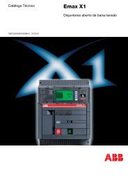
<strong>Feeder</strong> <strong>Protection</strong> <strong>Relay</strong><strong>REF</strong> <strong>610</strong>Fig. 3 Substation feeder O/C and E/F protection, and substation busbar protection based onRE_ <strong>610</strong> series protection relays. The operate time of the busbar protection has beenspeeded up using the principle of upstream interlockingThe connection of the CTs to the <strong>REF</strong> <strong>610</strong>relay depends on the available number andtypes of CTs in the feeder cubicle. Generallyan outgoing feeder is equipped with threephase current transformers for high- andlow-set overcurrent protection. The residualcurrent for the earth-fault protection can bederived from the three phase currents. It canalso be measured with a ring-type cable currenttransformer, should the outgoing feederbe a cable line and a sensitive earth-faultprotection be required.Should the feeder cubicle be equipped withtwo phase current transformers, the <strong>REF</strong> <strong>610</strong>relay can still be used for high- and low-setovercurrent protection including phase discontinuityand phase unbalance protection.<strong>ABB</strong>
<strong>Feeder</strong> <strong>Protection</strong> <strong>Relay</strong><strong>REF</strong> <strong>610</strong>1MRS75629511. CommunicationThe protection relays are connected to thefibre-optic communication bus directly or viabus connection modules and gateways.Thebus connection module converts the electricalsignals of the relay to optical signals forthe communication bus and, vice versa, theoptical signals of the communication bus toelectrical signals for the relay.Optional communication modules and protocolsProtocolPlastic fibre x)Plastic/Glass fibre x)RS-485 x)RS-485DNP x)SPA X X X -DNP 3.0 - - - XIEC 60870-5-103 X X X -Modbus (RTU and ASCII) X X X -IEC 61850 X X - -Bus connection modules and gatewaysIEDLON - - X -IED + SPA-ZC 402X X - -IED + SPA-ZC 102Profibus - - X -IED + SPA-ZC 21 + SPA-ZC 102IED + SPA-ZC 302x) Optional arc protection<strong>ABB</strong>
<strong>Feeder</strong> <strong>Protection</strong> <strong>Relay</strong><strong>REF</strong> <strong>610</strong>12. Technical dataDimensionsWidth frame 177 mm,case 164 mmHeight frame 177 (4U),case 160 mmDepth case 149.3 mmWeight relay 3.5 kgspare unit 1.8 kgPower SupplyType: <strong>REF</strong> <strong>610</strong>CxxHxxx <strong>REF</strong> <strong>610</strong>CxxLxxxU auxratedU auxvariation (temporary)Burden of auxiliary voltage supplyunder quiescent (P q)/operatingconditionRipple in DC auxiliary voltageU r= 100/110/120/220/240 V ACU r= 110/125/220/250 V DC85...110% x U r(AC)80...120% x U r(DC)
<strong>Feeder</strong> <strong>Protection</strong> <strong>Relay</strong><strong>REF</strong> <strong>610</strong>1MRS756295Measuring rangeMeasured currents on phases I L1, I L2and I L3as multiples ofthe rated currents of the energizing inputsEarth-fault current as a multiple of the rated current of theenergizing input0...50 x I n0...20 x I nDigital InputsRated voltage• <strong>REF</strong> <strong>610</strong>CxxHxxxActivating threshold• <strong>REF</strong> <strong>610</strong>CxxLxxxActivating threshold• <strong>REF</strong> <strong>610</strong>CxxxxHxActivating threshold• <strong>REF</strong> <strong>610</strong>CxxxxLxActivating thresholdOperating rangeCurrent drainPower consumption/inputDI1...DI2110/125/220/250 V DCMax. 88 V DC (110 V DC -20%)24/48/60/110/125/220/250 V DCMax. 19.2 V DC (24 V DC -20%)±20% of the rated voltage2...18 mA
<strong>Feeder</strong> <strong>Protection</strong> <strong>Relay</strong><strong>REF</strong> <strong>610</strong>1MRS756295Electromagnetic compatibility testsThe EMC immunity test level meets the requirements listed below:1 MHz burst disturbance test, class III:• Common mode• Differential modeElectrostatic discharge test, class IV:• For contact discharge• For air dischargeRadio frequency interference tests:• Conducted, common mode• Radiated, amplitude-modulated• Radiated, pulse-modulatedFast transient disturbance tests:• Power outputs, energizing inputs, power supply• I/O portsSurge immunity test:• Power outputs, energizing inputs, power supply• I/O portsPower frequency (50 Hz) magnetic fieldAccording to IEC 60255-22-12.5 kV1.0 kVAccording to IEC <strong>610</strong>00-4-2,IEC 60255-22-2 and ANSI37.90.3-20018 kV15 kVAccording to IEC <strong>610</strong>00-4-6 andIEC 60255-22-6 (2000)10 V (rms), f = 150 kHz...80 MHzAccording to IEC <strong>610</strong>00-4-3 andIEC 60255-22-3 (2000)10 V/m (rms), f = 80...1000 MHzAccording to the ENV 50204 andIEC 60255-22-3 (2000)10 V/m, f = 900 MHzAccording to IEC 60255-22-4,and IEC <strong>610</strong>00-4-44 kV2 kVAccording to IEC <strong>610</strong>00-4-54 kV, line-to-earth, 2 kV, line-toline2 kV, line-to-earth, 1 kV, line-toline300 A/m continuous, accordingto IEC <strong>610</strong>00-4-8Voltage dips and short interruptions According to IEC <strong>610</strong>00-4-1130%/10 ms60%/100 ms60%/1000 ms>95%/5000 msElectromagnetic emission tests:• Conducted, RF emission (Mains terminal)• Radiated RF emissionCE complianceAccording to the EN 55011EN 55011, class A, IEC 60255-25EN 55011, class A, IEC 60255-25Complies with the EMC directive89/336/EEC and the LV directive73/23/EEC<strong>ABB</strong> 11
<strong>Feeder</strong> <strong>Protection</strong> <strong>Relay</strong><strong>REF</strong> <strong>610</strong>Insulation testDielectric tests:• Test voltageImpulse voltage test:• Test voltageInsulation resistance measurementsIsolation resistanceAccording to IEC 60255-52 kV, 50 Hz, 1 minAccording to IEC 60255-55 kV, unipolar impulses, waveform1.2/50 μs, source energy 0.5 JAccording to IEC 60255-5>100 MΩ, 500 V DCMechanical testsVibration tests (sinusoidal)Shock and bump testAccording to IEC 60255-21-1, class IAccording to IEC 60255-21-2, class IData communication for front interfaceFront interface:• Optical connection (infrared) via the front communication cable (1MRS050698)• SPA bus protocol• 9.6 or 4.8 kbps (9.6 kbps with front communication cable)<strong>Protection</strong> functionsStage I>, I>> and I>>>Feature Stage I> Stage I>> Stage I>>>Set start value, I>, I>> and I>>>• at definite-time characteristic• at IDMT characteristic0.30...5.00 x I n0.30...2.50 x I na)0.50...35.0 x I n0.50...35.0 x I nStart time, typical 55 ms 30 ms 30 msTime/current characteristic• definite-time operate time, t>,t>> and t>>>• IDMT according to IEC 60255-3time multiplier, k• Special type of IDMTcharacteristictime multiplier, k• IDMT according toIEEE C37.112time dial, n0.05...300 sExtremely inverseVery inverseNormal inverseLong-time inverse0.05...1.00RI-type inverseRD-type inverse(RXIDG)0.05...1.00Extremely inverseVery inverseInverse1...150.04...300 s 0.04...300 s12<strong>ABB</strong>
<strong>Feeder</strong> <strong>Protection</strong> <strong>Relay</strong><strong>REF</strong> <strong>610</strong>1MRS756295(continued)Feature Stage I> Stage I>> Stage I>>>Resetting time, maximum 50 ms b) 50 ms 50 msRetardation time, typical 30 ms 30 ms 30 msSet resetting time, t r>0.05...2.50 sDrop-off/pick-up ratio, typical 0.96 0.96 0.96Operate time accuracy• at definite-time characteristic• at IDMT characteristic accordingto IEC 60255-3:accuracy class index E• at IDMT characteristic accordingto IEEE C37.112• at RI-type characteristic• at RD-type characteristic(RXIDG)Operation accuracy• 0.3...0.5 x I n• 0.5...5.0 x I n• 5.0...35.0 x I n±2% of the setoperate time or±25 ms5±7% of the calculatedoperatetime±7% of the calculatedoperatetime±7% of the calculatedoperatetime±5% of the setstart value±3% of the setstart value±2% of the setoperate time or±25 ms±3% of the setstart value±3% of the setstart value±2% of the setoperate time or±25 ms±3% of the setstart value±3% of the setstart valuea) As the maximum measured current is 50 × I n, a predefined current setting of 2.5 x I nis used for the operate timecalculation at IDMT mode of operation, if the set start value is greater than 2.5 x I n. This will speed up the operationof the relay making the operate time shorter than the theoretical IDMT curve would imply. However, the stage alwaysstarts according to the set start value.b) Resetting time of the trip signal.Stages I 0> and I 0>>Feature Stage I> Stage I>>Set start value, I 0> and I 0>>• at definite-time characteristic1.0...100% I n5.0...800% I n• at IDMT characteristica)1.0...100% I nStart time, typical 60 ms 50 ms<strong>ABB</strong> 13
<strong>Feeder</strong> <strong>Protection</strong> <strong>Relay</strong><strong>REF</strong> <strong>610</strong>1MRS756295Stage q>FeatureValueSet full load current, I q0.30...1.50 x I nSet alarm level, q a> 50...100%Trip level, q t> 100 %Time constant, τ1...200 minOperate time accuracy I/I q>1.2±2% of the set operate time or ±1 sStage ΔI>FeatureValueSet start value, ΔI> at definite-time characteristic 10...100% ΔI =(I max-I min)/I max*100%Start time, typical100 msTime/current characteristics definite time operatetime, tΔ>1...300 sResetting time, maximum70 msDrop-off/pick-up ratio, typical 0.90Operate time accuracy• at definite-time characteristic ±2% of the set operate time or ±75msOperation accuracy• 10...100%±3% of the set start value and ±1 unitStage ARCFeatureStage ARCSet trip value ArcI>Operate timeArcI 0>Operate timeResetting timeOperation accuracyLightSensor>Activation time of LightSensor>Resetting timeValue0.5...35.0 x I n< 15 ms a)5.0...800% I n< 17 ms a)30 ms±7% of the set start value< 15 ms20 msa) Applies only if a signal output contact (SO1...5) is used. If a power output contact (PO1...3) is used, 2...3 ms willbe added. It is used only for alarm purposes.<strong>ABB</strong> 15
<strong>Feeder</strong> <strong>Protection</strong> <strong>Relay</strong><strong>REF</strong> <strong>610</strong>Auto-reclose functionFeatureValueTrigger pulseAny start/trip signalNumber of shots 0...3CB Closing time0.1...10 sStart delay of stage I>0...300 sStart delay of stage I 0>0...300 sReclaim time3...300 sCutout time0.1...300 sDead time of shot 10.1...300 sDead time of shot 20.1...300 sDead time of shot 30.1...300 sOperate time accuracy±2% of the set time and ±25 msCBFPFeatureSet operate timePhase-current threshold for external triggering ofCBFP• pick-up/drop-offValue0.10...60.0 s0.08/0.04 x I n16<strong>ABB</strong>
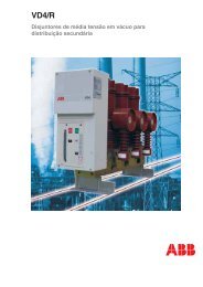
<strong>Feeder</strong> <strong>Protection</strong> <strong>Relay</strong><strong>REF</strong> <strong>610</strong>1MRS75629513. Mounting methodsUsing appropriate mounting accessories thestandard relay case for the RE_ <strong>610</strong> seriesrelays can be flush mounted, semi-flushmounted or wall mounted. The flush mountedand wall mounted relay cases can alsobe mounted in a tilted position (25°) usingspecial accessories.Further the relays can be mounted in anystandard 19” instrument cabinet by means of19” mounting panels, available with cut-outsfor one relay or two relays. Alternatively, therelays can be mounted in 19” instrumentcabinets by means of 4U Combiflex equipmentframes.For routine testing purposes the relay casescan be equipped with test switches typeRTXP 18 which can be mounted side by sidewith the relay cases.Mounting methods:• Flush mounting• Semi-flush mounting• Semi-flush mounting in a 25° angle• Rack mounting• Wall mounting• Mounting to a 19” equipment frame• Mounting with a RTXP 18 test switch toa 19” rack14. <strong>Relay</strong> case and relayplug-in unitAs a safety measure the relay cases for thecurrent measuring relays are provided withautomatically acting contacts for shortcircuitingthe CT secondaries when a relayplug-in unit is withdrawn from the relay case.In addition, the relay case is provided with amechanical coding system preventing currentmeasuring relay plug-in units from being insertedinto a case for a voltage relay unit andvice versa, i.e. the relay cases are associatedto a certain type of relay plug-in unit.There is, however, an universal relay caseavailable, which is not associated to a certainplug-in unit type. When a relay plug-in unitis plugged into such a relay case for the firsttime the relay case will automatically adaptto that particular relay type, i.e. the shortcircuitingcontacts will be activated as willthe mechanical blocking system. Hereafterthe relay case is permanently associated to acertain relay type. Fig. 4 Flush mounting Fig. 5 Semi-flush mounting Fig. 6 Semi-flush mountingin a 25° angle<strong>ABB</strong> 17
<strong>Feeder</strong> <strong>Protection</strong> <strong>Relay</strong><strong>REF</strong> <strong>610</strong>15. Selection andordering dataWhen ordering <strong>REF</strong> <strong>610</strong> protection relaysand/or accessories please specify the following:Order number, HMI language set numberand quantity. The order number identifies theprotection relay type and hardware as describedin the figures below and is labeled onthe marking strip under the lower handle ofthe relay.Use the ordering key information in Fig. 7 togenerate the order number when orderingcomplete protection relays. Fig. 7 Ordering key for complete relays18<strong>ABB</strong>
<strong>Feeder</strong> <strong>Protection</strong> <strong>Relay</strong><strong>REF</strong> <strong>610</strong>1MRS756295Use the ordering key information in Fig. 8 togenerate the order number when orderingspare units. Fig. 8 Ordering key for spare units<strong>ABB</strong> 19
<strong>Feeder</strong> <strong>Protection</strong> <strong>Relay</strong><strong>REF</strong> <strong>610</strong>16. Accessories andtoolsItemOrder nrCablesFront communication cable1MRS050698Cable for optical sensors for arc protection (X.X = length [m]) 1MRS120534-X.XMounting accessoriesSemi-flush mounting kit1MRS050696Inclined semi-flush mounting kit1MRS05083119 ” rack mounting kit with cutout for one relay 1MRS05069419 ” rack mounting kit with cutout for two relays 1MRS050695Surface mounting frame1MRS050697Mounting bracket for RTXP 181MRS061207Mounting bracket for 4U high Combiflex equipment frame 1MRS061208Test switches:Test switch RTXP 181MRS050783Optional communication cards:Plastic fibre1MRS050889Plastic fibre with inputs for arc protection1MRS050890RS-4851MRS050892RS-485 with inputs for arc protection1MRS050888Plastic and glass fibre1MRS050891Plastic and glass fibre with inputs for arc protection1MRS050885RS-485 including DNP 3.0 protocol1MRS050887RS-485 including DNP 3.0 protocol and inputs for arc1MRS050886RE_ <strong>610</strong> universal cases:Empty universal relay case for RE_ <strong>610</strong>1MRS050904Configuration, setting and SA system toolsCAP 501 <strong>Relay</strong> Setting Tool CAP 50CAP 505 <strong>Relay</strong> Setting Tool CAP 505SMS 510 Substation Monitoring SystemLIB 510 Library for MicroSCADA v. 8.4.4Versionv. 2.4.0-1 or laterv. 2.4.0-1 or laterSMS 510 v.1.2.0-1 or laterLIB 510 v. 4.0.5-3 or later20<strong>ABB</strong>
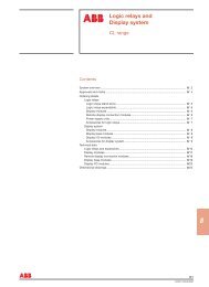
<strong>Feeder</strong> <strong>Protection</strong> <strong>Relay</strong><strong>REF</strong> <strong>610</strong>1MRS75629517. Terminal diagramFig. 9 Terminal diagram of <strong>REF</strong> <strong>610</strong><strong>ABB</strong> 21
<strong>Feeder</strong> <strong>Protection</strong> <strong>Relay</strong><strong>REF</strong> <strong>610</strong>18. Approvals<strong>REF</strong> <strong>610</strong> has been granted a preliminary EDFapproval:Number EDF R&D H-M2A-2006-02557-FR.19. ReferencesThe www.abb.com/substationautomation portaloffers you information about the distributionautomation product and service range.You will find the latest relevant informationon the <strong>REF</strong> <strong>610</strong> protection relay on theproduct page.The download area on the right hand sideof the web page contains the latest productdocumentation, such as technical referencemanual, installation manual, operators manual,etc. The selection tool on the web pagehelps you find the documents by the documentcategory and language.The Features and Application tabs containproduct related information in a compactformat.Fig. 10 Product page22<strong>ABB</strong>
1MRS756295<strong>ABB</strong> OyDistribution AutomationP.O. Box 699FI-65101 VAASA, FinlandPhone +358 10 22 11Fax +358 10 22 41094www.abb.com/substationautomationCopyright 2007 <strong>ABB</strong>