Linear Roller Way Super X
Linear Roller Way Super X
Linear Roller Way Super X
- No tags were found...

Create successful ePaper yourself
Turn your PDF publications into a flip-book with our unique Google optimized e-Paper software.
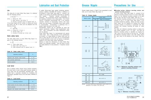
Lubrication and Dust ProtectionGrease NipplePrecautions for UseLifeThe rating life of <strong>Linear</strong> <strong>Roller</strong> <strong>Way</strong> <strong>Super</strong> X is obtainedfrom the following formula.CL50 103 1Pwhere, LRating life10 3 mCBasic dynamic load ratingNPDynamic equivalent loador Applied loadNIf the stroke length and the number or strokes per minuteare known, the life in hours can be obtained from thefollowing formula.10 6 LLh 22Sn160where,LhRating life in hourshS Stroke lengthmmn1Number of strokes per minutecpmStatic safety factorThe static safety factor of <strong>Linear</strong> <strong>Roller</strong> <strong>Way</strong> <strong>Super</strong> X isgiven in the following formula.where,C0fsP03fs Static safety factorC0Basic static load ratingNP0Static equivalent loador Applied loadNTable 10 Static safety factorOperating conditionsfSA quality lithium-soap base grease containing extremepressureadditivesALVANIA EP Grease 2SHELLispre-packed in <strong>Linear</strong> <strong>Roller</strong> <strong>Way</strong> <strong>Super</strong> X. However, thequality of any grease will gradually deteriorate as operatingtime passes. Therefore, periodic re-lubrication isnecessary. The re-lubrication interval varies depending onthe operating conditions of the rolling guides. A six monthinterval is generally recommended and, if the machineoperation consists of reciprocating motions with manycycles and long strokes, re-lubrication every three monthsis recommended. Re-lubrication is performed from agrease nipple provided at the slide unit.Re-lubrication interval can be extended by using thespecial specification Capillary Platesupplemental code“/Q”. Also, re-lubrication and other maintenance workscan be reduced.<strong>Linear</strong> <strong>Roller</strong> <strong>Way</strong> <strong>Super</strong> X is dust-protected with specialrubber seals. But, if large amounts of fine contaminantsare present, or if large particles of foreign matter such asdust or chips may fall on the track rail, it is recommendedto provide protective covers such as bellows or telescopicshields for the entire linear motion mechanism.Bellows to match the dimensions of <strong>Linear</strong> <strong>Roller</strong> <strong>Way</strong><strong>Super</strong> X are optionally available. They are easy to mountand highly effective for dust protection. If required, consult.Grease nipples shown in Table 12 are assembled to eachslide unit of <strong>Linear</strong> <strong>Roller</strong> <strong>Way</strong> <strong>Super</strong> X.Table 12 Grease nippleModel numberTypeLRX 12 AM3LRX 15 AM4LRX 20LRX 25BM4Grease nippleShape and dimensionWidth across flats4M3Width across flats4.5M4R32.1R3Approx. 67.55.13.7Width across flats6M46unitmm4.2 4.5646 10qMounting surface, reference mounting surface, andgeneral mounting structureTo mount <strong>Linear</strong> <strong>Roller</strong> <strong>Way</strong> <strong>Super</strong> X, correctly fit thereference mounting surfaces B and D of <strong>Linear</strong> <strong>Roller</strong> <strong>Way</strong><strong>Super</strong> X to the reference mounting surfaces of the tableand the bed, and then fix them tightly.See Fig. 4.The reference mounting surfaces B and D and mountingsurfaces A and C of <strong>Linear</strong> <strong>Roller</strong> <strong>Way</strong> <strong>Super</strong> X areaccurately finished by grinding. Stable and high accuracylinear motion can be obtained by finishing the matingmounting surfaces of machines or equipment with highaccuracy and correctly mounting the guide on thesesurfaces.The slide unit reference mounting surface is always theside surface opposite to the mark. The track railreference mounting surface is identified by locating themark on the top surface of the track rail. The trackrail reference mounting surface is the side surface abovethe markin the direction of the arrow.See Fig.5.CDOperation with vibration and/or shocks4 6High operating performanceNormal operationLoad factorDue to vibration and/or shocks during machine operation,the actual load on each rolling guide becomes greater inmany cases than the theoretically calculated load. Theapplied load is generally calculated by multiplying thetheoretically calculated load by the load factor indicated inTable 11.Table 11 Load factorOperating conditions3 52.53fWLRX 30LRX 35LRX 45LRX 55LRX 65LRX 85LRXG 100BM6Equivalent to A-M6FApprox. 67.5Width across flats8M60.75JIS AM6FJIS APT18JIS APT1412.56.5 13ABFig. 4 Reference mounting surfaces andgeneral mounting structureTrack railSlide unitReference mountingsurfaceDBSmooth operation free from vibration and/or shocksNormal operation1 1.21.21.5RemarkThe above table shows representative model numbers but isapplicable to all models of the same size.Operation with vibration and/or shocks1.53markmarkFig. 5 Reference mounting surfaces231N0.102kgf0.2248lbs.1mm0.03937inch24