MountingwMounting of the slide unitExcept the size 12 models, the slide unit is provided withone or two mounting thread holes in the middle of widthSee Fig. 6.so that an applied load can be received withgood load balance. When designing machines orequipment, ensure that these middle mounting holes of theslide unit can be securely tightened to obtain maximumperformance of the guide.It is recommended to secure the screwing depths shownin Table 13 for the slide units of compact block type.Middle mounting holeof the slide unitFig. 6 Middle mounting hole of the slide unitTable 13 Screwing depth of slide unit mountingholes for compact block typeModel numberLRXS 15LRXS 20LRXS 25LRXS 30Recommended minimumdepthmmRemarkThe above table shows representative model numbers but isapplicable to all models of the same size.eCorner radius and shoulder height of referencemounting surfacesIt is recommended to make a relieved fillet at the cornerof the mating reference mounting surfaces as shown inFig.7. However, in some series, corner radius R shownin Table 14 can also be used. Table 14 showsrecommended shoulder heights and corner radius of themating reference mounting surfaces.4.55.579Table 14 Shoulder heights and corner radius ofthe mating reference mounting surfacesh1RModel numberLRX 12LRX 15LRX 20LRX 25LRX 30LRX 35LRX 45LRX 55LRX 65LRX 85LRXG 100RSlide unitSlide unitShoulderheighth2RTrack railShoulderheightTrack railRCorner radiush1 h2 Rmax.4 2 0.54 3 0.55 4 0.56 5 18 5.5 18 5.5 18 7 1.510 8 1.510 10 1.514 14 2.514 13 2.5unitmmRemarkThe above table shows representative model numbers but isapplicable to all models of the same size.rMultiple slide units mounted in close distanceWhen using multiple slide units in close distance to eachother, actual load may be greater than the calculated loaddepending on the accuracy of the mounting surfaces andthe reference mounting surfaces of the machine. It issuggested in such cases to assume a greater load thanthe calculated load.qWhen mounting multiple sets at the same timeIn the case of interchangeable specification <strong>Linear</strong> <strong>Roller</strong><strong>Way</strong> <strong>Super</strong> X, assemble a slide unit and a track rail withthe same interchangeable code“S1” or “S2”.In the case of non-interchangeable specification <strong>Linear</strong><strong>Roller</strong> <strong>Way</strong> <strong>Super</strong> X, use an assembly of slide unit andtrack rail as delivered without changing the combination.Special specification products of matched setssupplemental code “/W”are delivered as a group inwhich dimensional variations are specially controlled.Mount them without mixing with the sets of another group.wAssembling a slide unit and a track railWhen assembling the slide unit on the track rail, correctlyfit the grooves of the slide unit to the grooves of the trackrail and move the slide unit gently in parallel direction.Rough handling will result in seal damage or dropping ofcylindrical rollers.The interchangeable specification slide unit is provided witha dummy rail. The size 12, 15, 20, 25 and 30 modelsof non-interchangeable specification are appended with adummy rail. This dummy rail should be used for assembly.eAccuracy of mating mounting surfacesA load greater than the calculated load may act on <strong>Linear</strong><strong>Roller</strong> <strong>Way</strong> <strong>Super</strong> X, depending on the accuracy of matingmounting surfaces and assembling accuracy. This willeventually give an adverse effect on the service life of<strong>Linear</strong> <strong>Roller</strong> <strong>Way</strong> <strong>Super</strong> X. Therefore, the accuracy mustbe carefully examined.The accuracy of mating mounting surfaces for track railand slide unit and the assembling accuracy must bedetermined considering the operating conditions, requiredrunning accuracy and rigidity, etc. Also, the mountingstructure must be examined to ensure accuracy andperformance for reliable use of a linear motion rollingguide.When multiple sets are mounted, the parallelism betweenthe two mounting surfaces of machines must be prepared,in general, as shown in Table 15.Table 15 Parallelism between two mountingsurfacesAccuracyclassHighHPrecisionP<strong>Super</strong>precisionSPunitmUltraprecisionUPFig. 8 Cleaning of mounting surfacestTightening torque of mounting boltsThe standard torque values for <strong>Linear</strong> <strong>Roller</strong> <strong>Way</strong> <strong>Super</strong>X mounting bolts are shown in Table 16. When machinesor equipment are subjected to severe vibration, shock,large fluctuating load, or moment load, the bolts should betightened with a torque 1.2 to 1.5 times higher than thestandard torque values shown.When the mating member material is cast iron oraluminum, tightening torque should be lowered inaccordance with the strength characteristics of the material.Table 16 Tightening torque of mounting boltsBolt sizeM 30.5M 40.7M 50.8M 61M 81.25M101.5M121.75M142M162Tightening torqueN-mCarbon steel bolt Stainless steel boltStrength division 12.9 Property division A2-701.7 1.14.0 2.57.9 5.013.3 8.532.0 20.462.7 108 172 263 Fig. 7 Relieved fillet at the corner of themating reference mounting surfacestOperating temperatureThe maximum operating temperature is 120C and acontinuous operation is possible at temperatures up to 100C. When the temperature exceeds 100C, consult .For the “with capillary plates”supplemental code “/Q”ofspecial specification, operate <strong>Linear</strong> <strong>Roller</strong> <strong>Way</strong> <strong>Super</strong> Xbelow 80C.Parallelism 30 20 10 6rCleaning of mounting surfacesBefore assembling <strong>Linear</strong> <strong>Roller</strong> <strong>Way</strong> <strong>Super</strong> X, removeburrs and blemishes from the reference mounting surfacesand mounting surfaces of the machine using an oil-stone,etc., and wipe off rust prevention oil and dirt with cleancloth.M202.5M243M303.5512 882 1 750 RemarkTightening torque for slide unit center mounting holes onflange typeLRXC, LRX, LRXGsize 15, 20, 25, 30, and35, are, recommended to be tightened with a torque 70 to80% values of table 16.251N0.102kgf0.2248lbs.1mm0.03937inch26
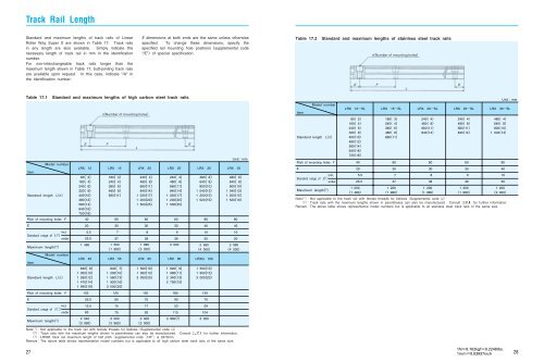
Track Rail LengthStandard and maximum lengths of track rails of <strong>Linear</strong><strong>Roller</strong> <strong>Way</strong> <strong>Super</strong> X are shown in Table 17. Track railsin any length are also available. Simply indicate thenecessary length of track rail in mm in the identificationnumber.For non-interchangeable track rails longer than themaximum length shown in Table 17, butt-jointing track railsare available upon request. In this case, indicate “/A” inthe identification number.E dimensions at both ends are the same unless otherwisespecified. To change these dimensions, specify thespecified rail mounting hole positionssupplemental code“/E”of special specification.Table 17.2 Standard and maximum lengths of stainless steel track railsnNumber of mounting holesEFLETable 17.1 Standard and maximum lengths of high carbon steel track railsItemStandard lengthStandard lengthLnPitch of mounting holesEStandard range ofMaximum length 2 ItemLnPitch of mounting holesEStandard range ofModel numberFincl.E 1 underModel numberMaximum length 2 Fincl.E 1 underELRX 1280 2160 4240 6320 8400104801256014640167201840105nNumber of mounting holesF60120L6015060180E80 802030303040 405.5 7 8 9 10 1025.5 37 38 39 50 501 480840 81 050101 260121 470141 9951952.56075907512.5 15 17 23 2965 75 92 113 1042 9403 990LRX 15 LRX 20 LRX 25 LRX 30 LRX 35180 3240 4360 6480 8660111 5001 980840 71 200101 560131 920163 000253 0003 960240 4480 866011840141 020171 200201 500251 9803 0001 500101 950133 000203 0003 900240 4480 866011840141 020171 200201 500253 0001 620 91 980112 340132 700152 880 3 480 6640 8800101 040131 200151 520192 9604 000LRX 45 LRX 55 LRX 65 LRX 85 LRXG 1001 500101 950133 000201503 000480 6640 8800101 040131 200151 520192 9604 000Note 1 Not applicable to the track rail with female threads for bellowsSupplemental code /J 2 Track rails with the maximum lengths shown in parentheses can also be manufactured. Consult for further information. 3 LRX85 track rail maximum length of half pitchsupplemental code/HPis 2970mm.RemarkThe above table shows representative model numbers but is applicable to all high carbon steel track rails of the same size.UnitmmItemStandard lengthModel numberLnPitch of mounting holesEStandard range ofFincl.E 1 underMaximum length 2 LRX 12SL LRX 15SL LRX 20SL LRX 25SL LRX 30SL80 2160 4240 6320 840010480125601464016720181 0001 480180 3240 4360 6480 866011240 4480 86601184014240 4480 86601184014480 4640 8800101 0401340 60 60 60 8020 30 30 30 405.5 7 8 9 1025.5 37 38 39 501 2001 9801 2001 9801 2001 9801 2002 000Note 1 Not applicable to the track rail with female threads for bellowsSupplemental code /J 2 Track rails with the maximum lengths shown in parentheses can also be manufactured. Consult for further information.RemarkThe above table shows representative model numbers but is applicable to all stainless steel track rails of the same size.Unitmm271N0.102kgf0.2248lbs.1mm0.03937inch28