FactoryCAD Tutorial 2
FactoryCAD Tutorial 2
FactoryCAD Tutorial 2

You also want an ePaper? Increase the reach of your titles
YUMPU automatically turns print PDFs into web optimized ePapers that Google loves.
<strong>FactoryCAD</strong> <strong>Tutorial</strong> 2July 10, 2003
ContentsProprietary Rights Notices.............................................................. 2Overviews ....................................................................................... 5Smart Factory Objects ..............................................................5Connectors ................................................................................5Understanding the interface......................................................6Getting Help..............................................................................7Repeating the tutorial................................................................7Setting up <strong>FactoryCAD</strong> ............................................................7Exercises ......................................................................................... 8Opening the tutorial drawing....................................................8Drawing a building grid............................................................8Adding a machine from the block library...............................10Adding an electrical line.........................................................11Adding a disconnect switch....................................................13Adding a pit ............................................................................15Adding a guardrail ..................................................................16Drawing a floor object............................................................17Adding a container..................................................................18Adding a rack..........................................................................19Creating a generic tool............................................................21Adding a safety fence .............................................................23Adding a mezzanine ...............................................................24Modifying a mezzanine ..........................................................25Appendix A — Movie files........................................................... 28Index ............................................................................................. 304 <strong>FactoryCAD</strong> <strong>Tutorial</strong> 2
OverviewsThe following overviews provide background information about essentialelements of <strong>FactoryCAD</strong>.Smart FactoryObjectsGraphical objects, also known as entities, are the visibleobjects (lines, circles, raster images, and so forth) that makeup a drawing. Each graphical object has methods thatallow an application to perform most of the AutoCADediting commands, such as Copy, Erase, Move, Mirror, andso forth. These objects also have methods for setting andretrieving extended data (xdata), highlighting and updating,and retrieving the bounding box of the object. Graphicalobjects have typical properties such as Layer, Linetype,Color, and Handle. They also have specific properties,depending on their object type, such as, Center, Radius, andArea.—ActiveX Automation User’s Guide, AutoCAD help fileThe Smart Factory Objects in the Factory programs bring unprecedentedease, accuracy, and speed to factory layout drafting. The Smart FactoryObjects enable the user to rapidly draft and edit in 2D whilesimultaneously creating a sophisticated 3D model. The Smart FactoryObjects are custom graphical objects.Custom graphical objects are visible objects (e.g., conveyors, lift tables,guard rails) that are created and displayed according to information andrules that are added to the base AutoCAD package. Each customgraphical object has methods that allow an application to perform most ofthe AutoCAD editing commands, such as Copy, Erase, Move, and Mirror.Custom graphical objects are typically much more complex than simpleAutoCAD objects, but they are much smaller than the simple AutoCADobjects that would be required to represent the same visible objects. Inaddition, custom graphical objects behave according to set characteristicsand rules. For example, when you stretch a guard rail, additional posts areautomatically added at the specified intervals.ConnectorsMany of the Smart Factory Objects, or custom objects, developed for usewith <strong>FactoryCAD</strong> and the other Factory programs include “connectors” atstrategic points. For example, a hold table on a skid cross aisle transferconveyor has a connector that can be used to automatically align andposition perpendicularly a skid conveyor. When connections are joined,moving one of the connected objects moves all of them as a group.Overviews - Smart Factory Objects 5
Many <strong>FactoryCAD</strong> routines include command-line prompts and options inaddition to a dialog box. Be sure to check the command line forinformation and prompts while executing a <strong>FactoryCAD</strong> function.Getting HelpThese tutorial procedures take you through a representative sample of<strong>FactoryCAD</strong> functionality. For more information on how to use any<strong>FactoryCAD</strong> feature, consult the online Help system.To open the <strong>FactoryCAD</strong> online Help system• On the Factory menu, point to Factory Layout Software Help. A submenuappears. Select <strong>FactoryCAD</strong> Help. The <strong>FactoryCAD</strong> online Helpsystem appears.-or-• In a <strong>FactoryCAD</strong> dialog box with a help button, click Help. The<strong>FactoryCAD</strong> online Help system window appears, opened to a topicrelated to the dialog box.Repeating thetutorialSetting up<strong>FactoryCAD</strong>Backup copies of the files needed for both foot-inch and metric versions ofthe tutorial are copied to sub-folders of the \BAKTUTOR folder within theprogram installation folder. To repeat the tutorial with a fresh set of files,copy the appropriate version from …\BAKTUTOR to the …\TUTORIALfolder.<strong>FactoryCAD</strong> runs inside an open session of AutoCAD or ArchitecturalDesktop. <strong>FactoryCAD</strong> is started by loading the Factory menu, and thenselecting <strong>FactoryCAD</strong> from that menu. See the Factory Programs Guidefor more information about installing and starting <strong>FactoryCAD</strong>.Overviews - Getting Help 7
2. In Default Column Spacing, type 25'.3. In Default Row Spacing, type 25'.4. Click Pick Corners. The dialog box temporarily disappears and thecommand prompt displaysSpecify first point:Note: The exterior walls have been drawn so that grid spacing of 25'fits evenly inside the building. If in Steps 5 and 6 you accidentallyselect an outside corner, rather than an inside corner, simply cancel thecommand and start over.5. Click the inside lower left corner of the building. The commandprompt displaysSpecify second point:6. Click the inside upper right corner of the building.If the spacing was set to other than 25' x 25', a message that gridspacing is uneven appears.7. (If an uneven spacing message appears) Click OK to close themessage.The Columns dialog box appears again, and the grid coordinates youjust selected appear in Start Corner and Opposite Corner.8. Click OK. <strong>FactoryCAD</strong> draws the building grid.Pull down the list of layers and notice that <strong>FactoryCAD</strong> automaticallycreated new layers:S-COL for the columnsS-GRD for the gridS-GRD-T for the text labelsAs you go on with the tutorial, you do not to need to change the grid, soclick the padlock icons in the layer list now to lock S-COL, S-GRD, andS-GRD-T layers.Note: If the layers were not created, <strong>FactoryCAD</strong> layer control is set tooff. To turn on layer control, on the Layer menu point to Layer Optionsand then click <strong>FactoryCAD</strong> Layer Control. At the command line type onand then press Enter. At the prompt for phased layout layer control, typeoff and then press Enter.Exercises - Drawing a building grid 9
Adding a machinefrom the blocklibrary<strong>FactoryCAD</strong>’s block manager enables easy, organized storage andretrieval of blocks. You can use the block manager now to get a machinefor your tutorial layout drawing.To insert a machine from the block library1. On the Block menu, select Block Manager. The Block Selection andInsertion dialog box appears.Note: When <strong>FactoryCAD</strong> is first installed, the library is automatically setto …\TUTORIAL\TUTOR3. If that library is not already selected, use Chlibto change to the TUTOR3 library. For complete information on using theBlock Manager, click Help in the Block Selection and Insertion dialog boxto open the online Help system.2. Click the MACHINE1 icon. The icon highlights and its descriptionappears in the Desc field.10 <strong>FactoryCAD</strong> <strong>Tutorial</strong> 2
3. Click OK. The dialog box closes and the command prompt displaysInsertion point:4. Select a point in the lower right corner of the factory. After you selecta point, an attribute dialog box appears.5. In Asset Number type a three- or four-digit number, and then click OK.If you zoom up to the machine, you’ll see that the asset number youentered appears on the machine, along with the machine description andtype.Tip: At this point you can pull down the list of layers and see that<strong>FactoryCAD</strong> has automatically created three new layers: MACH_DESC,MACH_NUM, and MACH_TYPE. The machine’s text description,number, and type are on the respective layers. Thus, the text visibility canbe controlled by freezing or thawing the corresponding layer.Adding an electricalline<strong>FactoryCAD</strong>’s layers dialog box displays a list of standard layers andprovides an easy means of adhering to drawing layer standards for itemssuch as electrical utility lines. The dialog box can be displayed byselecting Set Layer Dialog from the Layer menu. You can also display thelist just before running the respective command by selecting Line,Polyline, Dynamic Text, or Multiline Text from the El/Me, Arch, Ind, or Convmenus.To draw an electrical line on a standard layer1. If you are not already zoomed to the lower right corner of the building,zoom in now.2. On the El/Me menu, select Polyline. The List of Layers dialog boxappears. The Electrical/Mechanical category is already selected.Exercises - Adding an electrical line 11
3. In the Layer Description list, select Power, and then click OK.When you click OK, the current layer is set to E-pwr and the commandprompt displays the first prompt for the AutoCAD pline command:From point:4. Select points to draw an electrical line from the machine to a locationnear building column J0.You can easily label electrical and mechanical utility lines by selecting alabel from a standard list.To label an electrical line1. On the El/Me menu, select Electrical Lines. The Electrical Lines dialogbox appears.2. In the Categories list, click Power. A list of predefined electrical linesappears.3. Click 240VAC. The 240VAC line highlights.12 <strong>FactoryCAD</strong> <strong>Tutorial</strong> 2
4. Click OK. The dialog box closes, and the command prompt displaysSelect line/polyline or (Draw pline/Change values/Rotate last/Undo last):5. Select a point near the middle of a relatively long segment of theelectrical line you drew earlier. A text label is inserted into the line.6. Press Enter to end the command.Adding adisconnect switchNext, you can add a power disconnect switch symbol along the electricalpower line you just drew.To insert a disconnect switch1. On the El/Me menu, point to Electrical Symbols. A fly-out menuappears.2. Click Power. The Power Symbols dialog box appears.3. Click the Ext. Oper. Disconct icon. The icon highlights.Exercises - Adding a disconnect switch 13
4. Click OK. The command prompt displaysInsertion point:5. Select a point along the 240VAC electrical line. The commandprompt displaysRotation angle :6. Specify a rotation angle or simply press Enter to accept the defaultresponse.Note: If you pull down the list of layers, you’ll see that the layer E-lgtlisehas been created for the switch.14 <strong>FactoryCAD</strong> <strong>Tutorial</strong> 2
Adding a pitHeavy machines can often require special reinforcement beneath them.One way to identify this architectural feature is to draw a pit, which mightbe filled with reinforced concrete, beneath the machine.To insert a pit object1. From the Arch (Architectural) menu, select Pit. The Pit dialog boxappears.Pit is also available on the2. Click Draw a rectangular pit. The dialog box disappears and thecommand prompt displaysFirst inside corner:3. Select a point for an inside corner of the pit. The command promptthen displaysOther corner:4. Select a point for the diagonally opposite inside corner of the pit. ThePit dialog box reappears.5. Make sure that the Show X checkbox is marked, and then click OK.<strong>FactoryCAD</strong> draws the pit.For more information about the pit object, consult the online Help system.Exercises - Adding a pit 15
Adding a guardrailYou will often want a guardrail around pits or equipment. You can usethe guardrail object to easily add a guardrail.To add a guardrail1. On the Ind menu, select Guard Rail. The Guard Rail dialog boxappears.Guardrail is alsoavailable on theIndustrial_Objects toolbar.Guardrail shares a toolbarlocation with the Handrailicon.2. Click OK. The dialog box closes and the command prompt displaysPick first point:3. Select points to form the path along which you want a guardrail.When you have finished selecting points, press Enter. <strong>FactoryCAD</strong>draws the guardrail.16 <strong>FactoryCAD</strong> <strong>Tutorial</strong> 2
Drawing a floorobjectA floor object represents the thickness of the floor, can contain pits, andprovides a helpful frame of reference for rendered drawings.To draw a floor object1. Zoom so that the whole building is shown in plan view.Floor is alsoavailable on the Archtoolbar.2. From the Arch (Architectural) menu, select Floor. The Floors dialogbox appears.3. Click Draw Floor Boundary. The Floors dialog box disappears and thecommand prompt displaysSelect first point:4. Select an outside corner of the building. The command promptdisplaysNext point:5. Select the next outside corner. The command prompt displaysUndo/:6. Select the next outside corner. Note that <strong>FactoryCAD</strong> automaticallycloses the boundary with a diagonal line to the first point. Thecommand prompt displaysClose/ Perpendicular Close/Undo/:7. Select the last outside corner. The boundary line adjusts to form acomplete perimeter of the building. The command prompt displaysClose/ Perpendicular Close/Undo/:8. Press Enter to signal that you have finished drawing the boundary.The Floors dialog box reappears.9. Click OK. <strong>FactoryCAD</strong> creates the floor object.Note: If you pull down the list of layers, you see that a new layer Q-GENFLR has been created for the floor. <strong>FactoryCAD</strong> automatically locksExercises - Drawing a floor object 17
the layer to prevent accidentally selecting and modifying the floor object.To modify a floor object, place the cursor over a floor line and right-click.Options for modifying the floor appear at the command prompt. See theonline Help system for details.Adding a containerContainers are common objects in a factory, and <strong>FactoryCAD</strong>’s containerobject easily models a variety of container types.To add a container object1. On the Ind (Industrial) menu, point to Material Handling objects andthen select Containers. The Containers dialog box appears.Container is alsoavailable on the MaterialHandling toolbar.2. In the Container Text area at the bottom of the dialog box, type WASTEin the first box.3. Click OK. The dialog box closes and the command prompt displays:4. Select a point for the container location. The command prompt thendisplaysRotation angle :5. To specify the rotation angle, drag the cursor and then click, or type avalue and then press Enter. <strong>FactoryCAD</strong> inserts the container object.To resize the container object using grips1. Click the object. Blue grips appear at the corners.2. Click a corner grip. The grip turns red.3. Drag the grip. Notice that a length and width legend appears at the topleft of the drawing screen and is updated as you drag the grip.4. When the grip is in the desired location, click. The container objectand its dimension text update to the new size.Note: The AutoCAD OSNAP setting must be turned off while resizing thecontainer. SNAP may be turned on.18 <strong>FactoryCAD</strong> <strong>Tutorial</strong> 2
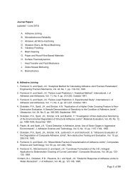
Adding a rackPerhaps one of the most versatile Smart Factory Objects, the rack objectnot only models a variety of rack types, but has been creatively used tomodel roof trusses and other regularly repeating geometry.Racks is alsoavailable on the MaterialHandling toolbar.To insert a rack object1. On the Ind (Industrial) menu, point to Racks and select Detail Rack.The Racks dialog box appears.2. In the Number of Bays Wide(NW), enter 2.3. In the Bay Span(BS) box, enter 60.4. Click OK. The dialog box closes and the command prompt displaysSpecify insertion point >5. Select a point near grid column A9. The command prompt displaysSpecify rotation angle :6. Type 90, and then press Enter. <strong>FactoryCAD</strong> inserts the rack object.To add another bay using grips1. Click the racks object. Grips appear.2. Click a grip on the end of the rack. The grip turns red.3. Drag the grip so it extends at least one bay width from the rack, andthen click. <strong>FactoryCAD</strong> adds another bay to the rack.2D and 3D views of rack with added bay, modified shelves in first bayExercises - Adding a rack 19
Shelf heights can be adjusted for each individual bay using the BayParameters tab of the Modify Racks Object dialog box.Note: You can right-click a smart factory object to display a menu thatincludes a Modify option. The Modify option displays an object’sparameters dialog box. When the view angle is other than plan view, forsome objects the shortcut menu is not accessible. Regardless of viewangle, an object’s dialog box can be displayed using the Modify Objectbutton on the toolbar containing the object’s creation icon.To adjust individual bay parameters1. On the Industrial_Objects toolbar, click the Modify Object icon .The command prompt displaysSelect Factory Object to modify:Note: See page 6 for a description of how to display <strong>FactoryCAD</strong> toolbars.2. Click the rack object. The Modify Rack Object dialog box appears.3. Click the Bays Parameters tab. The Bays Parameters page appears.4. In the Bay Number box, select the bay you wish to modify.5. Enter new settings for the selected bay.Tip: Detailed instructions regarding the Bays Parameters tab are in theonline Help system. Click Help in the dialog box to display the relevanttopic.6. Click OK. <strong>FactoryCAD</strong> makes the specified changes to the rack.You can see the effect of shelf height settings by switching to a SW orother 3D view.20 <strong>FactoryCAD</strong> <strong>Tutorial</strong> 2
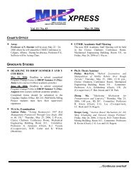
Creating a generictoolYou can use the Generic Tool object to automatically switch betweendifferent representations of an item, for example one representation whenin plan view and another when in an isometric view. The representationsare references to blocks.The Generic Tool object’s ability to reference blocks is valuable in severalsituations:• When complex geometry is not needed and would slow down drawingresponse unnecessarily, the display of the referenced blocks cantemporarily be disabled, and then restored later.• When individual blocks are not available in detailed or final format atthe time the layout drawing is being created, a placeholder generic toolobject can be created and inserted. When new or updated tool geometryis later available, the generic tool can be modified to use that geometry.Separate representations of 2D and3D blocksSeparate 2D and 3D representations ofan extruded polyline border.Example 2D and 3D representations managed by a Generic Tool objectTo create a generic tool1. On the Layers menu, select Set Layer Dialog. The List of Layers dialogbox appears.2. In the Categories list, select Industrial. The Layer Description listshows a list of standard industrial layers.3. Scroll to the bottom of the Layer Description list and select Processoperations/stations.Exercises - Creating a generic tool 21
Note: If your <strong>FactoryCAD</strong> is configured to use other than the defaultgeneric layer standards file, your list may be different. In that case, selectan appropriate layer name.4. Click OK.5. On the Industrial_Objects toolbar, click the Generic Tool icon .The Generic Tool dialog box appears.6. In the Tool Name box, type Punch.7. Click Top File. The 2D Top View Block Name file selection dialog boxappears.8. Look in the …\<strong>Tutorial</strong>\Tutor3 folder.9. Select 2DPUNCH.DWG, and then click Open. The file selection dialogbox closes and the file name 2DPUNCH appears in the Generic Tooldialog box.10. Click 3D File. The 3D Block Name file selection dialog box appears.11. Double-click the file 3DPUNCH.dwg. The file selection dialog boxcloses and the file name 3DPUNCH appears in the Generic Tool dialogbox.12. Click the checkboxes for 3D Block Name and Top View so that theycontain a .Notice that the default Rectangle Length and Rectangle Width values are1'.13. Click OK. The dialog box closes and the command prompt displaysSpecify insertion point14. Select a location and then a rotation angle for the tool. <strong>FactoryCAD</strong>inserts the generic tool object.At the time of insertion, <strong>FactoryCAD</strong> determines the smallest rectangularboundary that will enclose the block, and draws that rectangle around the2D block.To substitute an extruded polyline for referenced blocks1. Right-click the punch generic tool object. A menu appears.2. Select Modify. The Generic Tool dialog box appears.22 <strong>FactoryCAD</strong> <strong>Tutorial</strong> 2
1. Click the checkboxes for 2D Block Name and 3D Block Name so thatthey are empty.Notice that the Rectangle Length and Rectangle Width values havebeen adjusted.2. In Extrusion Depth, type 60.3. Click OK. The dialog box closes and the punch generic tool objectnow appears using a representation of the extruded polyline border,rather than the referenced blocks.Adding a safetyfenceSafety fence around tools is a common requirement. You can use thesafety fence object to easily create a range of safety fence configurations,including a variety of door options.To create a safety fence1. On the Ind (Industrial) menu, point to Safety Fence. A sub-menuappears.2. Select Safety Fence.... The Safety Fence dialog box appears.3. Click OK. The dialog box closes and at the command line a prompt forthe first point appears.4. Select points to form a path along which you want a safety fence.When you have finished selecting points, press Enter. <strong>FactoryCAD</strong>draws the safety fence.To add a door to a safety fence1. Move the cross-hairs over the safety fence and right-click. The safetyfence shortcut menu appears.Exercises - Adding a safety fence 23
Note: If snap is on and your snap settings are such that the cursor crosshairsdo not actually line up over safety fence geometry, the safety fenceshortcut menu does not appear. In that case, turn snap off temporarily.2. Select Add Door. The Safety Fence Door dialog box appears.3. From the Style drop-down list, select Sliding Door.4. Click OK. The dialog box closes and the command prompt displaysSelect safety fence and location:5. Select a point on the safety fence. A door symbol appears on theselected safety fence.6. Drag the door symbol around the fence until it is in a position youwant, then click. <strong>FactoryCAD</strong> draws the door.The side of the safety fence on which the sliding door is initially inserteddepends on which direction you went when you drew the safety fence.The side can easily be changed using grips.To change the fence side of a sliding safety fence door1. Click the door. Three grips appear along the door opening and onealong the door.2. Click the grip along the door. The grip turns red.3. Drag the pointer to the other side of the safety fence, and then releasethe mouse button. <strong>FactoryCAD</strong> moves the door to the other side of thefence.Adding amezzanine<strong>FactoryCAD</strong>’s mezzanine object can model an infinite variety ofmezzanine constructions. You can use the following steps to create arectangular mezzanine.24 <strong>FactoryCAD</strong> <strong>Tutorial</strong> 2
-or-• In a <strong>FactoryCAD</strong> dialog box with a help button, such as theMezzanine dialog box, click Help. The <strong>FactoryCAD</strong> online Helpsystem window appears, opened to a topic related to the dialog box.2. In the navigation pane at the left of the Help window, click Search.The Search tab appears.3. In the Type in the keyword to find box, type mezzanine.4. Click List Topics. A list of topics containing the word mezzanineappears in the Select topic area.5. In the list of topics, double-click Cutting a mezzanine section. Thetopic Cutting sections from a mezzanine or platform appears.Note: You could also find the topic in the table of contents at Addingobjects > Adding industrial objects > Mezzanines and platforms >Cutting holes in decks.To add stairs to a mezzanine1. Select a mezzanine object and then right-click. The mezzanineshortcut menu appears.2. On the shortcut menu, point to Factory and then select Add Stairs. TheStairway dialog box appears.3. Click OK. The dialog box closes and a stair icon appears at thecrosshairs. At the command line a prompt for the insertion pointappears.4. Move the stairs into position along the mezzanine. As long as you staynear the mezzanine edge, the stairs snap to the edge of the mezzanine.5. When the stairs are in position, click the left mouse button.<strong>FactoryCAD</strong> draws the stairs.Note: The stairs object will not draw stairs that exceed the maximumchange in elevation allowed by OSHA for a single flight of stairs. If agreater change in elevation is needed, add a landing at the end of the stairsobject, and then add another set of stairs.To add a landing to a stairs object1. In plan view, move the pointer over a stairs object and right-click. Thestairs shortcut menu appears.26 <strong>FactoryCAD</strong> <strong>Tutorial</strong> 2
2. Select Add Landing. A landing object appears at the pointer location.3. Move the landing into position at the foot of the stairs. When you arenear the connector at the end of a stairs object, the landing snaps intoplace.4. When the landing is in position, click the left mouse button.<strong>FactoryCAD</strong> draws the landing.To add stairs to a landingFollow the same procedure as for adding stairs to a mezzanine. Note thatyou can have <strong>FactoryCAD</strong> automatically adjust the stairs to meet aspecific height by entering a value in Ending Elevation of the stairwaydialog box.Exercises - Modifying a mezzanine 27
Appendix A — Movie filesThe following movie files are available from the Factory file downloadarea of the GTAC support site, http://support.plms-eds.com.auto_conv_1.avibelt conveyor.avibridge_crane.avibuff_calc3.avicabinets.avi.container.aviconvanim.aviCostEst0006.aviShows the use of Smart Factory Objects to construct and modify anautomotive floor conveyor system. In a 2D top view, a skid conveyor isinserted, a cross aisle transfer and lift table are snapped on, and anotherskid is added. Switches to 3D view, drags a grip to lengthen the last skid,drags another grip to simultaneously shorten the cross aisle transferconveyor and move the connected skid conveyor.Shows simultaneous 2D and 3D views as a belt conveyor section isinserted, and then lengthened using a grip. Drive side is changed using theshortcut menu and object dialog box. A new section is added using theshortcut menu and object dialog box. The conveyors are rendered.Shows simultaneous 2D and 3D views as a two-rail bridge crane system iscreated between building columns. The crane is dropped into the drawingand modified using grip points. The shortcut menu and object dialog boxare used to switch the crane from below the rails to above the rails.Shows selection of generic tools and connecting floor conveyors, thenshows the use of the Production Throughput Optimization Calculator tocompute required buffer size, buffer allocation, and throughput.Shows simultaneous top and front views as a cabinet is inserted andmodified. Grips are used to stretch the cabinet width and automaticallyadd doors. The shortcut menu and object dialog box are used to changethe cabinet height and alternate the door swing. The front view is changedto a SW view to show the 3D appearance of the cabinet.Shows simultaneous 2D and 3D views as a series of containers areinserted and modified. Solid wall, mesh, and no wall containers areinserted. A tote with different dimensions and elevation is inserted.Containers are repositioned and resized using grips.Shows construction of an overhead power and free conveyor, includingmodification to add a vertical curve section, followed by animation of acarrier and load along the track.Shows simultaneous 2D and 3D views of modification of amezzanine/platform, addition of a guard rail, then cost estimation: extractsinformation, compiles estimate, looks at computed costs.28 <strong>FactoryCAD</strong> <strong>Tutorial</strong> 2
CostEst0009.aviGMdemo_short_7Mg.avigrc.aviguardrail.avijib_crane.avimezzanine.avioverhead.aviplatform.aviracks.avisafety_fence.avivblr conveyor.aviSimilar to CostEst0006.avi except final phase is a little shorter.Simultaneous fly-through and animation of rendered layout with engineson roller package conveyor. Created in VisMockUp.Shows simultaneous 2D and 3D views as a gravity roller conveyor straightsection is dropped in, then lengthened using grips. Note the automaticaddition of standard length sections. Adds a curve section using theshortcut menu and object dialog box. Adds a new straight section withWheel Rollers option; renders the conveyors to show render view.Shows simultaneous 2D and 3D views of the creation of a guard rail,modifies the length by dragging a grip, modifies rail type (2 rails to 3rails) using the shortcut menu and object dialog box.Shows simultaneous 2D and 3D views of creation of jib crane,modification of jib length and swing arc by dragging a grip.Shows 2D creation of a rectangular mezzanine, cutting out a section, andaddition of stairs. Switches to 3D view, adds landing and stairs. Modifiesbottom stairs to extend to floor level.Shows simultaneous 2D and 3D views of the creation of an overheadpower and free conveyor, including vertical curve and addition of biasbank section.Shows 2D creation of dual-sided platform and modification of one sideusing grips. Switches to 3D view, uses the shortcut menu and objectdialog box to show railing. Note that by design, the inside platform edgedoes not have a railing.Shows simultaneous top and front views as a rack is created. Showsmodification of shelf height in one bay of a rack using the shortcut menuand object dialog box. Switches front view to SW view to show 3D rack.Shows simultaneous 2D and 3D views of creation of safety fence around atool. Modifies fence using grips. Uses shortcut menu and door dialog boxto add a door. Uses shortcut menu and object dialog box to change thefence pattern.Shows simultaneous 2D and 3D views of the creation of v-belt live rollerconveyor sections. Initial straight segment length is modified using grips.Display of a motor is added using the shortcut menu and object dialogbox. A new curved segment is added using the shortcut menu and objectdialog box. The curve section is dragged to a new location, and a newstraight section is automatically added to lengthen the system accordingly.The views are then rendered.Appendix A — Movie files - CostEst0009.avi 29
Indexbayadding using grips, 19adjusting parameters of, 20Block Manager, 10building grid, drawing, 8connectors, 5containeradding, 18resizing using grips, 18disconnect switch, adding, 13dooradding to a safety fence, 23changing the fence side of, 24electrical linedrawing, 11labelling, 12<strong>FactoryCAD</strong>, setting up, 7floor object, drawing, 17generic tool, creating, 21guardrail, adding, 16Help, displaying, 7Industrial_Objects toolbar,displaying, 6landings and stairs, 26List of Layers dialog box, 11mezzanineadding stairs to, 26creating, 24cutting out a section of, 25movie files, 28pit, adding, 15rackadding a bay using grips, 19inserting, 19safety fenceadding a door, 23creating, 23shortcut menus, displaying, 6stairsadding a landing to, 26adding to a mezzanine, 26and landings, 26toolbarsdisplaying, 6Industrial_Objects, 6tutorial, repeating, 730 <strong>FactoryCAD</strong> <strong>Tutorial</strong> 2