Recent Developments in Multifunctional Nanocomposites Using ...
Recent Developments in Multifunctional Nanocomposites Using ...
Recent Developments in Multifunctional Nanocomposites Using ...

Create successful ePaper yourself
Turn your PDF publications into a flip-book with our unique Google optimized e-Paper software.
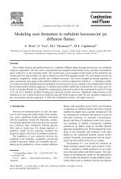
Jacob M. WernikShaker A. Meguid 1e-mail: meguid@mie.utoronto.caDepartment of Mechanical and IndustrialEng<strong>in</strong>eer<strong>in</strong>g,Mechanics and Aerospace Design Laboratory,University of Toronto,5 K<strong>in</strong>g’s College Road,Toronto, ON, M5S 3G8, Canada<strong>Recent</strong> <strong>Developments</strong> <strong>in</strong><strong>Multifunctional</strong> <strong>Nanocomposites</strong>Us<strong>in</strong>g Carbon NanotubesThis review summarizes the most recent advances <strong>in</strong> multifunctional polymer nanocompositesre<strong>in</strong>forced by carbon nanotubes and aims to stimulate further research <strong>in</strong> thisfield. Experimental and theoretical <strong>in</strong>vestigations of the mechanical, thermal, and electricalproperties of carbon nanotubes and their composite counterparts are presented.This review identifies the process<strong>in</strong>g challenges associated with this class of materialsand presents techniques that are currently be<strong>in</strong>g adopted to address these challenges andtheir relative merits. This review suggests possible future trends, opportunities, and challenges<strong>in</strong> the field and <strong>in</strong>troduces the use of these multifunctional nanocomposites <strong>in</strong>structural health monitor<strong>in</strong>g applications. DOI: 10.1115/1.4003503Keywords: carbon nanotubes, nanocomposites, nanotailor<strong>in</strong>g, nanore<strong>in</strong>forcement,multifunctional, structural health monitor<strong>in</strong>g1 IntroductionIt has been recognized for sometime that the mechanical, thermal,and electrical properties of polymeric materials can be eng<strong>in</strong>eeredby fabricat<strong>in</strong>g composites that are comprised of differentvolume fractions of one or more re<strong>in</strong>forc<strong>in</strong>g phases. Traditionally,polymeric materials have been re<strong>in</strong>forced with carbon or glassmicrofibers to improve their mechanical properties and a varietyof metallic and/or organic fillers for electrical and thermal propertyenhancements. These composite materials have been used <strong>in</strong>a wide variety of applications <strong>in</strong> automotive, aerospace, masstransit, and nuclear <strong>in</strong>dustries. Rarely, however, have traditionalfillers been able to substantially improve a comb<strong>in</strong>ation of theseproperties. As time has progressed, practical realization of suchcomposites has begun to shift from microscale composites tonanocomposites, tak<strong>in</strong>g advantage of the unique comb<strong>in</strong>ation ofmechanical, electrical, and thermal properties of nanofillers fillerswith a characteristic dimension below 100 nm. There are anumber of advantages associated with dispers<strong>in</strong>g nanofillers <strong>in</strong>polymeric materials. While some credit can be attributed to the<strong>in</strong>tr<strong>in</strong>sic properties of the fillers, most of these advantages stemfrom the extreme reduction <strong>in</strong> filler size comb<strong>in</strong>ed with the largeenhancement <strong>in</strong> the specific surface area and <strong>in</strong>terfacial area theypresent to the matrix phase. In addition, whereas traditional compositesuse over 40 wt % of the re<strong>in</strong>forc<strong>in</strong>g phase, the dispersionof just a few weight percentages of nanofillers <strong>in</strong>to polymericmatrices could lead to dramatic changes <strong>in</strong> their mechanical 1,2,thermal 3,4, and electrical 5 properties with added functionalities.Perhaps the most widely used and studied nanofiller is the carbonnanotube CNT. CNTs are highly unusual electrical conductors,the strongest known fibers, and excellent thermal conductors.In fact, some CNTs are stronger than steel, lighter than alum<strong>in</strong>um,and more conductive than copper 6. Theoretical and experimentalstudies have shown that CNTs exhibit extremely high tensilemodulus 1 TPa and strength 150 GPa. Depend<strong>in</strong>g ontheir atomic structure, CNTs can be either metallic or semiconduct<strong>in</strong>gwith experimental measurements show<strong>in</strong>g <strong>in</strong>tr<strong>in</strong>sic electricalconductivities of approximately 10 5 –10 6 S/m for metallicnanotubes and 10 S/m for semiconduct<strong>in</strong>g nanotubes. Furthermore,CNTs exhibit large phonon mean free paths that result <strong>in</strong>1 Correspond<strong>in</strong>g author.Published onl<strong>in</strong>e February 18, 2011. Transmitted by Editor: J. N. Reddy.high thermal conductivities, which have been theoretically estimatedto be <strong>in</strong> the range of 6000–3000 W/m K. In addition, CNTsexhibit high flexibility, low density 1.3–1.4 g/cm 3 , and largeaspect ratios 1000 s. Due to this unique comb<strong>in</strong>ation of physicaland multifunctional properties, CNTs have emerged as excellentcandidates for use as tailor<strong>in</strong>g agents <strong>in</strong> polymeric materials toyield next generation multifunctional composite materials.The ability to tailor the mechanical, thermal, and electricalproperties of polymeric materials through the dispersion of CNTsdepends on several important factors. The first is the propertybe<strong>in</strong>g tailored. Both mechanical and electrical properties seem tobe more sensitive to the CNT concentrations and geometrical parameterswhen compared with thermal properties. For example,Thostenson et al. 7 studied the <strong>in</strong>fluence of nanotube concentrationon the electrical properties of the CNT/v<strong>in</strong>yl-ester composites.At a concentration of only 0.1 wt % of CNTs, the volumeresistivity decreased by over eight orders of magnitude. The limitthat governs the sudden transition between <strong>in</strong>sulat<strong>in</strong>g and conduct<strong>in</strong>gbehaviors is known as the percolation threshold, whichwill be given more attention <strong>in</strong> the com<strong>in</strong>g discussions. Gojny etal. 8 demonstrated that the addition of as little as 0.1 wt % ofCNTs <strong>in</strong> an epoxy matrix can <strong>in</strong>crease the fracture toughness byupward of 20% with further improvements observed for am<strong>in</strong>ofunctionalizednanotubes. In comparison, the thermal conductivityof cured nanotube-epoxy composites shows a m<strong>in</strong>imal and near<strong>in</strong>significant <strong>in</strong>crease with nanotube content, less that 0.5% for aconcentration of 0.5 wt % of CNTs 9.A second aspect to consider when tailor<strong>in</strong>g the properties is thechoice of CNT and polymeric medium to which it is dispersed.The enhancement <strong>in</strong> thermal conductivities appears to be greaterfor s<strong>in</strong>gle-walled carbon nanotubes SWCNTs than for carbonnanofibers CNFs 10, probably reflect<strong>in</strong>g the <strong>in</strong>tr<strong>in</strong>sic propertiesof the fillers. Furthermore, the mechanical properties of nanocompositeshave been shown to <strong>in</strong>crease significantly when the CNTsare chemically modified to form reactive bridges with the surround<strong>in</strong>gpolymer cha<strong>in</strong>s 11–14, a process known as functionalization.In this context, the same CNTs can be shown to provide awide range of improvements <strong>in</strong> the mechanical properties fromthis surface modification process.The addition of CNTs <strong>in</strong> polymeric materials does not alwaysresult <strong>in</strong> improved properties. Several important factors relat<strong>in</strong>g tothe process<strong>in</strong>g of the nanocomposite also play a significant role.One of the most important aspects to consider is the homogeneousdispersion of the nanofillers <strong>in</strong> the polymeric matrix. CNTs tend toApplied Mechanics Reviews Copyright © 2010 by ASME SEPTEMBER 2010, Vol. 63 / 050801-1Downloaded 02 Mar 2011 to 128.100.48.220. Redistribution subject to ASME license or copyright; see http://www.asme.org/terms/Terms_Use.cfm
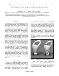
exhibit an enormous surface area be<strong>in</strong>g several orders of magnitudelarger than the surface of conventional fillers. The large surfacearea of CNTs leads to two counteract<strong>in</strong>g effects: one desirableoffer<strong>in</strong>g <strong>in</strong>creased stress transfer and the other undesirablelead<strong>in</strong>g to strong attractive <strong>in</strong>termolecular and van der Waalsforces between the nanofillers result<strong>in</strong>g <strong>in</strong> excessive agglomeration.The result<strong>in</strong>g aggregates act as defect sites rather than re<strong>in</strong>forcements,which could lead to a subsequent degradation of thenanocomposite properties. An efficient utilization of CNT properties<strong>in</strong> polymeric materials is therefore directly related to theirhomogeneous dispersion <strong>in</strong> the matrix. This tendency for thenanofillers to agglomerate also limits the concentration of thenanofillers that can be dispersed <strong>in</strong> the media. Meguid and Sun15 showed that the homogeneous dispersion of CNTs <strong>in</strong> an epoxyadhesive can improve the bond<strong>in</strong>g and shear properties ofcomposite <strong>in</strong>terfaces. However, they showed that there was anoptimal CNT concentration above which the properties of thecomposite beg<strong>in</strong> to degrade to below that of the pure epoxy <strong>in</strong>dicativeof the sensitivity of these properties on the nanofillerconcentration.Clearly, there are a number of important factors to consider <strong>in</strong>the design and fabrication of nanocomposite materials. It is thereforethe purpose of this review to summarize the latest developments<strong>in</strong> this field and identify the process<strong>in</strong>g challenges associatedwith this class of materials and the techniques currently be<strong>in</strong>gadopted <strong>in</strong> treat<strong>in</strong>g them. The general term nanocomposite can beused to reflect any composite material with a re<strong>in</strong>forc<strong>in</strong>g phaseexhibit<strong>in</strong>g a characteristic dimension below 100 nm. In fact, nanofillerssuch as carbon blacks, silicas, and clays have widely been<strong>in</strong>corporated <strong>in</strong>to a variety of host materials such as polymers,ceramics, and metallic matrices constitut<strong>in</strong>g a nanocomposite material.However, the focus of this review is on the nanotailor<strong>in</strong>g ofthe mechanical, thermal, and electrical properties of polymericmaterials through the homogeneous dispersion of CNTs.The layout of this review paper is as follows. Section 2 willdiscuss the structure, mechanical, thermal, and electrical propertiesof CNTs. Section 3 will focus on the experimental and numerical<strong>in</strong>vestigations of polymer nanocomposites re<strong>in</strong>forced withCNTs, with attention given to both thermoset and thermoplasticmatrix phases. This section will also address some of the challengesassociated with the design and fabrication of these materials.Section 4 will discuss a fasc<strong>in</strong>at<strong>in</strong>g and emerg<strong>in</strong>g applicationof these materials that exploits their multifunctional capabilities,namely, structural health monitor<strong>in</strong>g SHM <strong>in</strong> civil and aerospace<strong>in</strong>dustries. F<strong>in</strong>ally, Sec. 5 will summarize the current challengesand future outlook of this field.2 Carbon NanotubesCarbon nanotubes exhibit a remarkable comb<strong>in</strong>ation of mechanical,electrical, and thermal properties. As such, many potentiallyimportant applications have been explored, <strong>in</strong>clud<strong>in</strong>g the useof nanotubes as nanoprobe tips 16, field emitters 17–20, storageor filter<strong>in</strong>g media 21, and nanoscale electronic devices22–26, just to name a few. Their discovery, together with earliertheoretical predictions of a “nanosupermaterial,” stimulated enormous<strong>in</strong>terest <strong>in</strong> the field of nanomaterials. A large percentage ofacademic and popular literature attributes the discovery of CNTsto Iijima <strong>in</strong> 1991 27. However, there are several papers publishedwell before that time that identified the nanoscale carbonaceousfibers <strong>in</strong> several controlled experiments 28,29. For example,a paper published <strong>in</strong> 1976 by Oberl<strong>in</strong> et al. 28 clearlydepicted an <strong>in</strong>dividual CNT synthesized us<strong>in</strong>g a hydrocarbon decompositiontechnique, which is reproduced <strong>in</strong> Fig. 1. However,due to the magnification and resolution limitations of electronmicroscopes at that time, they were unable to resolve the <strong>in</strong>dividualgraphene fr<strong>in</strong>ges, and it was not claimed by the authors tobe <strong>in</strong> fact a CNT. It is, however, Iijima 27 who was responsiblefor report<strong>in</strong>g the structural perfections of CNTs and, hence, impliedthe extraord<strong>in</strong>ary properties that have been realized today. InFig. 1†28‡…this section, we review the mechanical, electrical, and thermalproperties of CNTs, which make them ideal candidates for theabovementioned applications.2.1 Structure. Carbon nanotubes occur <strong>in</strong> two general forms:SWCNTs and multiwalled carbon nanotubes MWCNTs.SWCNTs can generally be visualized as a s<strong>in</strong>gle sheet of graphenethat has been rolled <strong>in</strong>to a hollow tubular shape. The orientation ofthe graphene sheet as it is rolled will dictate the result<strong>in</strong>g structureof the CNT. SWCNTs can have diameters as small as 0.4 nm andnormally no larger than 2 nm. MWCNTs can be viewed as severalconcentric SWCNTs with outside diameters that range between 5nm and 100 nm. The <strong>in</strong>terlayer spac<strong>in</strong>g of MWCNTs is approximately0.34 nm 30,31, and this value is also widely taken as thethickness of <strong>in</strong>dividual CNT layers <strong>in</strong> numerical simulations32–35 and <strong>in</strong> some experimental <strong>in</strong>vestigations 36,37. Figure 2depicts both the SWCNT and MWCNT structures.A schematic illustration of an unrolled graphene sheet is shown<strong>in</strong> Fig. 3. CNTs are def<strong>in</strong>ed by a pair of <strong>in</strong>dices n,m, which areused to identify their atomic structure and size. These <strong>in</strong>dicescorrespond to a lattice vector R=nr 1 +mr 2 on the graphene plane,where r 1 and r 2 are unit vectors <strong>in</strong> the hexagonal lattice, and n andm are <strong>in</strong>tegers. This lattice vector maps onto the circumference ofthe result<strong>in</strong>g nanotube cyl<strong>in</strong>der. The orientation of the graphitelattice relative to the longitud<strong>in</strong>al axis def<strong>in</strong>es the chirality or helicityof the nanotube 38. Two ma<strong>in</strong> symmetry groups exist:armchair n,n and zigzag n,0 configurations, with all othern,m comb<strong>in</strong>ations referred to as chiral nanotubes. The CNT radiusand chiral angle can be determ<strong>in</strong>ed from the follow<strong>in</strong>g simpleexpressions:Fig. 2Early bright field SEM image of a MWCNT „from Ref.r CNT = 3r o2 n 2 + mn + m 2Two CNT variants: „a… a SWCNT and „b… a MWCNT1050801-2 / Vol. 63, SEPTEMBER 2010 Transactions of the ASMEDownloaded 02 Mar 2011 to 128.100.48.220. Redistribution subject to ASME license or copyright; see http://www.asme.org/terms/Terms_Use.cfm
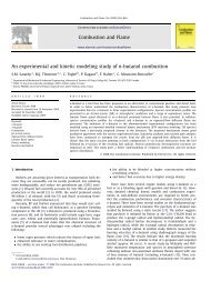
Fig. 3Unrolled graphene sheet and the chiral lattice vector = cos −12n + m2 n 2 + mn + m 2where r o is the equilibrium bond length normally taken to be0.1421 nm. A variant of the CNT is the CNF. CNFs differ fromnanotubes <strong>in</strong> the way the graphene sheet is oriented with respectto the fiber axis. Unlike CNTs, which have the graphene sheetorientated parallel to the fiber axis, CNFs can have a wide rangeof orientations of the graphitic layers. These nanostructures arebest visualized as nanoscale cones or disks stacked atop one another,as shown <strong>in</strong> Fig. 4. They can also be hollow and typically2have outside diameters <strong>in</strong> the range of 50–100 nm.A noticeable feature of the graphene sheet is the hexagonalpattern, which is repeated periodically <strong>in</strong> space. Each carbon atom<strong>in</strong> the lattice is covalently bonded to three neighbor<strong>in</strong>g atoms.This hexagonal structure is attributed to the sp 2 hybridization process.One s-orbital and two p-orbitals of a carbon atom <strong>in</strong> itsexcited state comb<strong>in</strong>e to form three hybrid sp 2 -orbitals at 120 degrelative to each other. This sp 2 hybridization process is illustrated<strong>in</strong> Fig. 5. The result<strong>in</strong>g covalent bond, known also as the -bond,is a strong chemical bond, which is largely responsible for theunique properties of CNTs. The other relatively weak out-of-planebond, known as the -bond, is typically exploited <strong>in</strong> functionalizationprocesses, which <strong>in</strong>volve the graft<strong>in</strong>g of functional groupson the walls of CNTs as a means of improv<strong>in</strong>g their <strong>in</strong>terfacialbond<strong>in</strong>g with a surround<strong>in</strong>g polymer matrix.2.2 Mechanical Properties. Early theoretical and experimentalworks have confirmed that CNTs possess exceptional mechanicalproperties. To date, a number of researchers have employedboth experimental and theoretical techniques to determ<strong>in</strong>e the mechanicalproperties of CNTs. However, due to the extremely smallsize of CNTs, the experimental studies are challeng<strong>in</strong>g, and theresults normally show significant variability. This could also beattributed to differences <strong>in</strong> the CNT structure, exist<strong>in</strong>g defects,and synthesis techniques. Experimental techniques approximateCNTs as elastic structural members and, <strong>in</strong> so do<strong>in</strong>g, impose cont<strong>in</strong>uumassumptions. As a consequence, the experimental measurementsare faced with the problem of def<strong>in</strong><strong>in</strong>g the crosssectionalarea of the CNTs. Most approaches approximate thecross-sectional area to be equal to that of a hollow th<strong>in</strong> walledcyl<strong>in</strong>der, namely, dt, where t is taken as the <strong>in</strong>terlayer spac<strong>in</strong>g ofgraphene 36,37.Although the test<strong>in</strong>g of <strong>in</strong>dividual nanotubes is a challeng<strong>in</strong>gtask, a number of techniques have been developed to provideFig. 4 TEM images of commercial CNFs, highlight<strong>in</strong>g structural variations <strong>in</strong> the orientation of the graphiticplanes „from Ref. †347‡…Fig. 5sp 2 hybridization process and the result<strong>in</strong>g - and -bondsApplied Mechanics Reviews SEPTEMBER 2010, Vol. 63 / 050801-3Downloaded 02 Mar 2011 to 128.100.48.220. Redistribution subject to ASME license or copyright; see http://www.asme.org/terms/Terms_Use.cfm
Fig. 6 SEM images show<strong>in</strong>g a SWCNT rope under direct tensileload<strong>in</strong>g us<strong>in</strong>g AFM „from Ref. †37‡…<strong>in</strong>sights <strong>in</strong>to their mechanical behavior and to quantify these properties.The experimental techniques used range from direct tensileload<strong>in</strong>gmeasurements to techniques based on observ<strong>in</strong>g theirfreestand<strong>in</strong>g room temperature vibrations <strong>in</strong> a transmission electronmicroscope TEM. For example, Lourie and Wagner 39measured the cool<strong>in</strong>g-<strong>in</strong>duced compressive response of CNTs us<strong>in</strong>gmicro-Raman spectroscopy. Young’s moduli of both SWCNTsand MWCNTs were then derived from a concentric cyl<strong>in</strong>dermodel <strong>in</strong>volv<strong>in</strong>g thermal stresses. In their study, Lourie and Wagnerreported Young’s moduli of 2.8–3.6 TPa and 1.7–2.4 TPa forSWCNT and MWCNT, respectively. In comparison, Yu et al.37,40 determ<strong>in</strong>ed the Young’s modulus to range from 320 GPato 1470 GPa and from 270 GPa to 950 GPa for SWCNT ropes and<strong>in</strong>dividual MWCNTs, respectively, us<strong>in</strong>g atomic force microscopyAFM. Figure 6 shows scann<strong>in</strong>g electron microscope SEM imagesof the SWCNT rope multitudes of entangled CNTs tensileload<strong>in</strong>gexperiment conducted by Yu et al. where both pre-andpost-loaded CNTs are depicted. Several experimental reports ofYoung’s modulus values for both SWCNTs and MWCNTs areprovided <strong>in</strong> Table 1 along with their respective references anddetails of their methodology.Experimental measurements of the tensile strengths of CNTshave also been conducted. However, they are limited due to thedifficulties associated with the application of direct tensile loadson <strong>in</strong>dividual CNTs. The tensile strengths of SWCNT ropes were<strong>in</strong>vestigated by Walter et al. 43 via AFM. They assumed Young’smodulus of 1.25 TPa <strong>in</strong> their calculations and, <strong>in</strong> so do<strong>in</strong>g, obta<strong>in</strong>edtensile strengths of 457 GPa. In the study by Yu et al.40, the tensile strengths of MWCNTs ranged from 11 GPa to 63GPa. The MWCNTs were also shown to fail via a sword-andsheathtype mechanism, where the outer layer first fractured andthe <strong>in</strong>ner layers were subsequently pulled out. Weak load transferwas observed between the <strong>in</strong>ner and outer layers of the MWCNTwith <strong>in</strong>terfacial shear strengths ISSs of 0.08 MPa and 0.3 MPaaris<strong>in</strong>g from the weak van der Waals <strong>in</strong>teractions between thesubsequent layers. The weak load transfer between the subsequentlayers was also demonstrated by Cum<strong>in</strong>gs and Zettl 44. Theyused a movable nanomanipulator <strong>in</strong>side a high-resolution TEM towithdraw the <strong>in</strong>ner layer of a MWCNT from its surround<strong>in</strong>g outerlayer. The measured <strong>in</strong>terfacial shear strength aris<strong>in</strong>g from the vander Waals <strong>in</strong>teractions was determ<strong>in</strong>ed to be <strong>in</strong> the range of 0.43–0.66 MPa. They also demonstrated controlled and reversible telescopicextension of MWCNTs whereby the <strong>in</strong>ner layer is withdrawnunder direct load<strong>in</strong>g, and upon removal of the load, itretracts back as a result of the attractive van der Waals<strong>in</strong>teractions.Researchers have used model<strong>in</strong>g methods account<strong>in</strong>g for alllength scales to characterize the behavior of CNTs. First pr<strong>in</strong>ciplequantum mechanical descriptions have been employed to modelthe structural deformation 45, fracture 46, defect nucleation47, chemical reactivity 48,49, and functionalization 50,51 of<strong>in</strong>dividual CNTs. Classical molecular dynamics MD and molecularmechanic simulations have been shown to play an importantrole <strong>in</strong> determ<strong>in</strong><strong>in</strong>g the constitutive relations of CNTs underdifferent load<strong>in</strong>g conditions 52–54, CNT growth mechanisms55, oscillatory properties 56, and the effects of chirality andlength on the mechanical properties 57. At the coarser end of thelength scale, cont<strong>in</strong>uum mechanical concepts have also been used<strong>in</strong> characteriz<strong>in</strong>g the CNT behavior. In cont<strong>in</strong>uum-based approaches,the CNT is modeled as a cont<strong>in</strong>uous shell with a fixedwall thickness and material properties 58–60. However, the onlyway of dist<strong>in</strong>guish<strong>in</strong>g between nanotubes of different chiralitieszigzag, armchair, and chiral is through the radius of the shell.The disadvantages of this approach are that the CNT is drasticallyoversimplified, it cannot be used to study the effect of defects, andthe atomic structure of the CNT has been ignored. Nevertheless,cont<strong>in</strong>uum-based approaches have been shown to reasonably predictthe tensile and shear moduli of <strong>in</strong>dividual CNTs 61,62 andtheir deformation and stability under different loads 60,63,64.Additionally, a number of multiscale approaches have also beenpursued 65. The theoretical predictions tend to overestimate themechanical properties when compared with experimental f<strong>in</strong>d<strong>in</strong>gs,which assume that the CNT is a defect-free structure. At the sametime, it is easier to <strong>in</strong>vestigate the effect of such parameters astemperature, stra<strong>in</strong> rate, defect nucleation, chirality, size, and differentload<strong>in</strong>g conditions <strong>in</strong> theoretical approaches. In this context,the elastic properties of CNTs are rarely presented as s<strong>in</strong>glevalues but rather as vary<strong>in</strong>g functions of the diameter or chirality.Due to the shear number of theoretical efforts made <strong>in</strong> this field,the reader is referred to a review by Ruoff et al. 66 for furtherdetails.2.3 Electrical Properties. The electrical properties of CNTshave also attracted a great deal of <strong>in</strong>terest from the research community.Their nanoscale dimensions, coupled with the uniqueelectronic structure of the host graphene sheet, lead to a variety ofunique electrical properties. These properties have been extensively<strong>in</strong>vestigated both theoretically and experimentally 67–83.However, as with the mechanical properties, measurements of theelectronic properties of <strong>in</strong>dividual CNTs are challeng<strong>in</strong>g. Earlytheoretical studies conducted by Hamada et al. 84, M<strong>in</strong>tmire etal. 85, and Saito et al. 86 showed that the electronic propertiesof CNTs were heavily dependent on their geometric structure,namely, the diameter and chirality. These theoretical studies basedon tight-b<strong>in</strong>d<strong>in</strong>g calculations predicted that CNTs can act either asmetals or as semiconductors with different sized energy bandgaps, which depend on the above parameters. The chiral <strong>in</strong>dicesTable 1Experimental measurements of carbon nanotube Young’s modulusAuthor Technique CNT type Young’s modulus Ref.Lourie and Wagner Micro-Raman spectroscopy SWCNT 2.8–3.6 TPa 39Micro-Raman spectroscopy MWCNT 1.7–2.4 TPa 39Yu et al. AFM SWCNT rope 320–1470 GPa 37,40AFM MWCNT 270–950 GPa 37,40Tombler et al. AFM SWCNT 1.2 TPa 36Krishnan et al. TEM/vibrational theory SWCNT 0.9–1.7 TPa 41Salvetat et al. AFM SWCNT rope 0.810.41 TPa 42050801-4 / Vol. 63, SEPTEMBER 2010 Transactions of the ASMEDownloaded 02 Mar 2011 to 128.100.48.220. Redistribution subject to ASME license or copyright; see http://www.asme.org/terms/Terms_Use.cfm
Fig. 7Metal and semiconduct<strong>in</strong>g nanotubes as a function of their chiral <strong>in</strong>dicesn,m can be used to determ<strong>in</strong>e whether a CNT will act as a metal,a large band gap semiconductor, or a t<strong>in</strong>y band gap semiconductor.The general rules are such that all armchair n,n nanotubesare metals, n,m nanotubes with n−m=3j, where j is a nonzero<strong>in</strong>teger, are small band gap semiconductors, and all others arelarge band gap semiconductors. Accord<strong>in</strong>gly, approximately onethirdof SWCNTs are metals, while the other two-thirds are consideredsemiconductors. This is <strong>in</strong> agreement with experimentalobservations, which have little or no control on the chirality of thetest specimens. Figure 7 illustrates some of these different possibilitiesas a function of the chiral <strong>in</strong>dices.The CNT size has also been shown to have a significant effecton the electrical properties. As the radius of the nanotube <strong>in</strong>creases,the band gap decreases for both small and large band gapsemiconductors with respective 1/R and 1/R 2 dependence 87.Asimilar observation has been made for CNTs with very small diameters.It was found that strong hybridization effects can occur<strong>in</strong> these nanotubes, lead<strong>in</strong>g to a decrease <strong>in</strong> the energy band gapsby nearly 50% 87, thus provid<strong>in</strong>g them with superconductiveproperties 88. CNTs with such a small diameter distribution areconf<strong>in</strong>ed to 3,3, 4,2, and 5,0 configurations. The electricalproperties of these CNTs have already been extensively studiedus<strong>in</strong>g ab <strong>in</strong>itio methods 89–91.The first experimental measurements of <strong>in</strong>dividual SWCNTswere carried out by Tans et al. 71. These experiments verifiedthe theoretical predictions and confirmed that CNTs can displayboth metallic and semiconduct<strong>in</strong>g properties. The electrical conductivityat room temperature was measured to be approximately10 5 –10 6 S/m for metallic nanotubes and approximately 10 S/mfor semiconduct<strong>in</strong>g nanotubes. Furthermore, theoretical predictionswere verified us<strong>in</strong>g scann<strong>in</strong>g tunnel<strong>in</strong>g microscopy STMexperiments conducted by Odom et al. 92 and Wilder et al. 93.They showed that the electrical properties of CNTs depend upontheir geometrical parameters. In these experimental measurements,the resolution allowed for the identification of <strong>in</strong>dividualcarbon r<strong>in</strong>gs. The structure of the CNTs was then determ<strong>in</strong>ed fromthe orientation of the carbon r<strong>in</strong>gs and the diameter of the CNTs.In comparison, the conductivity of SWCNT bundles has beenfound to vary between 110 4 S/m 94 and 310 6 S/m95,96 at room temperature. Furthermore, the electrical conductivitiesof <strong>in</strong>dividual MWCNTs have also been <strong>in</strong>vestigated experimentally.They have been reported to range between 20 S/mand 210 7 S/m 97, depend<strong>in</strong>g on the helicities of the outermostshells 98 and the presence of defects 99. Defects such asthe Stone-Wales defect, vacancies, and impurities have all beenfound to affect the electrical properties 100,101. The extent towhich the properties are affected would depend on the number ofdefects, their proximity to each other, and the nanotube structureconsidered. Furthermore, structural deformations such as twist<strong>in</strong>gand bend<strong>in</strong>g can also produce variations <strong>in</strong> the conductivities ofCNTs 102–104. Therefore, the <strong>in</strong>troduction of defects <strong>in</strong> CNTsand/or deform<strong>in</strong>g CNTs can be viewed as an <strong>in</strong>terest<strong>in</strong>g way ofchang<strong>in</strong>g their electrical properties.2.4 Thermal Properties. The study of the thermal propertiesof CNTs has received considerably less attention <strong>in</strong> comparison totheir mechanical and electrical properties. However, there existpublications that describe experimental and theoretical <strong>in</strong>vestigations<strong>in</strong>to such thermal properties as their specific heat, thermalconductivity, and thermal expansion. As with the mechanical andelectrical experiments, the thermal measurements were also madeon a s<strong>in</strong>gle nanotube. Such measurements are very difficult. Consequently,SWCNT thermal conductivities have primarily beenevaluated theoretically. Experimental results exist only forSWCNT bundles and <strong>in</strong>dividual MWCNTs.The unique crystal structure of CNTs, together with their highaspect ratios, led to early speculations that the longitud<strong>in</strong>al thermalconductivity of CNTs could exceed that of the host materialgraphite 105. Indeed, CNTs do have a very high thermal conductivity,which arises from the strong covalent bond<strong>in</strong>g betweenthe carbon atoms. The theoretical predictions of Berber et al.106 based on molecular dynamics simulations have predictedtheir room temperature thermal conductivities to be as high as6600 W/m K, which surpasses that of diamond 2000 W/m K.Berber et al. also calculated the thermal conductivities ofSWCNTs over a range of temperatures. They found that the conductivitypeaks near 100 K and subsequently decreases with <strong>in</strong>creas<strong>in</strong>gtemperature. The peak value was determ<strong>in</strong>ed to be37,000 W/m K, which is comparable to the highest thermal conductivityever measured 41,000 W/m K 107. In comparison,the theoretical MD predictions of Osman and Srivastava 108showed that the peak value occurs at around room temperature fora number of SWCNTs with diameters <strong>in</strong> the range of 1–2 nm anddifferent chiralities. This room temperature conductivity was determ<strong>in</strong>edto be approximately 2500 W/m K. The decrease <strong>in</strong> thermalconductivity at higher temperatures can be expla<strong>in</strong>ed by phononscatter<strong>in</strong>g events. As the temperature <strong>in</strong>creases, more andmore phonons contribute to the heat flow <strong>in</strong> the system. However,at high temperatures, phonon-phonon scatter<strong>in</strong>g events beg<strong>in</strong> todom<strong>in</strong>ate, and the subsequent heat flow decreases, as depicted <strong>in</strong>Applied Mechanics Reviews SEPTEMBER 2010, Vol. 63 / 050801-5Downloaded 02 Mar 2011 to 128.100.48.220. Redistribution subject to ASME license or copyright; see http://www.asme.org/terms/Terms_Use.cfm
Fig. 8 Molecular dynamics predictions of the thermal conductivityof a „10,10… nanotube. The characteristic peak<strong>in</strong>g behavioroccurs at approximately 100 K „from Ref. †106‡….Fig. 8.The experimental measurements of Li 109 also showed a peakvalue <strong>in</strong> the thermal conductance occurr<strong>in</strong>g at around room temperature310 K for SWCNT bundles. In addition, the experimentalmeasurements of Hone et al. 110 of bulk SWCNT samplesover a temperature range of 0 K to 300 K also <strong>in</strong>dicate an <strong>in</strong>crease<strong>in</strong> thermal conductivity with <strong>in</strong>creas<strong>in</strong>g temperature. Their measurementsshowed a decrease <strong>in</strong> the slope occurr<strong>in</strong>g at the hightemperature range. However, the characteristic peak<strong>in</strong>g behaviorwas not evident as the temperature range was not extended beyond300 K. It is difficult to determ<strong>in</strong>e the <strong>in</strong>tr<strong>in</strong>sic thermal conductivities<strong>in</strong> these experimental measurements because the numberof SWCNTs contribut<strong>in</strong>g to the heat flow cannot bedeterm<strong>in</strong>ed. These measurements confirm that phonon-phononscatter<strong>in</strong>g events become important at near room temperature forSWCNT bundles. In the above experimental measurements, theroom temperature conductivities for the SWCNT bundles rangefrom 2.3 W/m K to 35 W/m K. However, the nanotubes <strong>in</strong> thesesamples are highly entangled, and the thermal pathway is considerablylonger than the direct distance between the po<strong>in</strong>ts of measurement.To avoid the irregularities and random distribution <strong>in</strong>the above samples, Hone 111 used magnetically alignedSWCNT th<strong>in</strong> films for his measurements. The measured thermalconductivity of these samples <strong>in</strong>creased with temperature up to400 K, reach<strong>in</strong>g a maximum value of approximately 200 W/m K,which is approximately an order of magnitude higher than thehighest value obta<strong>in</strong>ed for the random entangled samples. Thethermal conductivities of MWCNT have also been <strong>in</strong>vestigatedexperimentally by Small et al. 112 over a temperature range of 8K to 370 K. Aga<strong>in</strong>, the conductivity <strong>in</strong>creases with <strong>in</strong>creas<strong>in</strong>gtemperature up to a maximum value of 3000 W/m K at a temperatureof approximately 300 K. In contrast, bulk samples ofMWCNTs exhibit a thermal conductivity of only 25 W/m K atroom temperature 113. The high thermal conductivities of bothSWCNTs and MWCNTs show tremendous potential for CNTs tobe used <strong>in</strong> thermal management applications such as heat s<strong>in</strong>ks <strong>in</strong>electrical circuitry.The relatively large variation among the different measurementsof thermal conductivity of both MWCNTs and SWCNTsare due to <strong>in</strong>consistencies among the CNTs of the experimentalsetups. CNTs can be synthesized us<strong>in</strong>g a variety of different techniques,<strong>in</strong>clud<strong>in</strong>g chemical vapor deposition CVD, arc discharge,and laser ablation, to name a few. Depend<strong>in</strong>g on themanufactur<strong>in</strong>g technique used, the nanotubes could have differentstructures, sizes, purities, and, more importantly, defectdistributions/concentrations. As with both the mechanical andelectrical properties, it is expected that the <strong>in</strong>tr<strong>in</strong>sic thermal conductivityof CNTs will be affected by the abovementioned parameters.For example, defects act as phonon scatter<strong>in</strong>g sites, thuslimit<strong>in</strong>g the <strong>in</strong>tr<strong>in</strong>sic conductivity of the nanotube. Che et al. 114used molecular dynamics simulations to <strong>in</strong>vestigate the effect ofboth vacancy and Stone-Wales defects on the <strong>in</strong>tr<strong>in</strong>sic conductivity.They found that the <strong>in</strong>tr<strong>in</strong>sic thermal conductivity decreasedsignificantly with <strong>in</strong>creas<strong>in</strong>g defect density with a more severedegradation observed with the vacancy defects. Their results arecomplemented by the recent study of Fan et al. 115. Similarly,Yan et al. 116 developed an analytical model to show that thethermal conductivities of SWCNTs and MWCNTs are <strong>in</strong> fact bothdiameter and chirality dependent. Their results clearly suggest thatthe thermal conductivity <strong>in</strong>creases with decreas<strong>in</strong>g nanotube diameter.The phonon scatter<strong>in</strong>g processes are suppressed <strong>in</strong> smalldiameter nanotubes, giv<strong>in</strong>g rise to high thermal conductivity.This section of the review has <strong>in</strong>troduced the extraord<strong>in</strong>ary mechanical,thermal, and electrical properties of CNTs. It is due tothese properties that researchers are <strong>in</strong>troduc<strong>in</strong>g CNTs as tailor<strong>in</strong>gagents <strong>in</strong> polymeric materials. It presents the opportunity to <strong>in</strong>troduceboth thermally and electrically conductive capabilities to thehost matrix, meanwhile improv<strong>in</strong>g its mechanical performance. Amaterial with such multifunctional capabilities can f<strong>in</strong>d numerousapplications <strong>in</strong> a variety of <strong>in</strong>dustries. However, composites conta<strong>in</strong><strong>in</strong>gCNTs have not yet realized their full potential. This can beattributed to a number of difficulties associated with the process<strong>in</strong>gof this class of materials. These process<strong>in</strong>g challenges areaddressed <strong>in</strong> the follow<strong>in</strong>g section.3 <strong>Multifunctional</strong> CNT Polymer CompositesNow that the <strong>in</strong>tr<strong>in</strong>sic mechanical, electrical, and thermal propertiesof CNTs have been explored, we are <strong>in</strong> a position to discusstheir ability to tailor the properties of polymeric materials to yieldmultifunctional nanocomposites. <strong>Recent</strong> work <strong>in</strong> this area showsthat the scientific community is adopt<strong>in</strong>g a variety of differentmethods to develop these nanotailored composites with vary<strong>in</strong>glevels of success. The properties of CNT polymer composites are<strong>in</strong>fluenced by a number of factors that <strong>in</strong>clude the CNT synthesisand purification process, the geometrical and structural propertiesof the CNTs, their alignment <strong>in</strong> the matrix, the dispersion process,and the fabrication process. In the follow<strong>in</strong>g sections, we willdiscuss the process<strong>in</strong>g challenges associated with this class ofmaterials and the techniques used by the research community toovercome them. Specifically, emphasis will be placed on the techniquesused to disperse CNTs <strong>in</strong> polymeric matrices, the differentfunctionalization processes, which ultimately lead to more stableCNT solutions, and the different techniques used to align CNT <strong>in</strong>the matrix. The mechanical, electrical, and thermal properties ofCNT polymer nanocomposites and the parameters that <strong>in</strong>fluencethem will then be explored both from experimental and theoreticalstandpo<strong>in</strong>ts.3.1 Dispersion and Functionalization. One of the most importantaspects to consider <strong>in</strong> the fabrication of polymer nanocompositesis the homogeneous dispersion of the nanofillers <strong>in</strong>to thepolymeric matrix. The ultimate goal of the dispersion process is tobreak up nanotube agglomerates and homogeneously distributethe <strong>in</strong>dividual CNTs throughout the matrix. CNTs tend to exhibitan enormous surface area be<strong>in</strong>g several orders of magnitude largerthan the surface of conventional fillers due to their nanoscopicsize and large aspect ratios. The large surface area of CNTs leadsto two counteract<strong>in</strong>g effects: one desirable offer<strong>in</strong>g <strong>in</strong>creasedstress transfer and the other undesirable lead<strong>in</strong>g to excessive agglomerationdue to <strong>in</strong>termolecular van der Waals forces. van derWaals forces are the weakest type of <strong>in</strong>termolecular forces and arecreated by the attraction between <strong>in</strong>duced dipoles <strong>in</strong> a nonpolarmolecule. The van der Waals <strong>in</strong>teractions between CNTs are notablylarger than van der Waals <strong>in</strong>teractions between polymercha<strong>in</strong>s because of the absence of hydrogen atoms. This attraction,coupled with their nanoscopic size and high aspect ratios, leads toconsiderable aggregation. The result<strong>in</strong>g aggregates act as defectsites rather than re<strong>in</strong>forcements, lead<strong>in</strong>g to a degradation <strong>in</strong> theproperties of the nanocomposite 117. An efficient utilization ofthe nanofiller properties <strong>in</strong> polymeric materials is therefore relatedto their homogeneous dispersion <strong>in</strong> the matrix. Of equal impor-050801-6 / Vol. 63, SEPTEMBER 2010 Transactions of the ASMEDownloaded 02 Mar 2011 to 128.100.48.220. Redistribution subject to ASME license or copyright; see http://www.asme.org/terms/Terms_Use.cfm
Fig. 9 Ultrasound <strong>in</strong>duced cavitation stages from „a… the nucleation of avoid and „b… its unstable growth to „c… its implosiontance is the stability of the result<strong>in</strong>g dispersion. It is desirable thatthe CNTs rema<strong>in</strong> <strong>in</strong> their uniformly dispersed state after process<strong>in</strong>gand not re-agglomerate as a result of their attractive<strong>in</strong>teractions.The dispersion, aggregation, agglomeration, and entanglementof CNTs are a subject of current <strong>in</strong>tensive research 118–121.Most strategies comb<strong>in</strong>e the use of mechanical and chemicalroutes. The mechanical route <strong>in</strong>cludes high shear<strong>in</strong>g techniquesus<strong>in</strong>g mechanical stirr<strong>in</strong>g, sonication, microfluidiz<strong>in</strong>g, and calender<strong>in</strong>g.These methods <strong>in</strong>volve impos<strong>in</strong>g high shear forces on theCNT/polymer mixture that leads to the homogeneous dispersionof the CNTs. Chemical strategies, on the other hand, typically<strong>in</strong>volve either a covalent modification of the surface of the CNTor the use of a dispersant or surfactant, be<strong>in</strong>g polymeric or supramolecular<strong>in</strong> nature. The chemical strategies are more effective<strong>in</strong> prevent<strong>in</strong>g the re-agglomeration of the CNTs after the dispersionprocess has been carried out. A number of factors will determ<strong>in</strong>ethe state of the result<strong>in</strong>g dispersion. However, to date, theonly way of assess<strong>in</strong>g the quality of the dispersion is throughelectron microscopy imag<strong>in</strong>g techniques, which can be fairly limited<strong>in</strong> terms of provid<strong>in</strong>g a large spatial field of view. Often, onlysmall sections of the sample are exam<strong>in</strong>ed, which may lead to an<strong>in</strong>accurate assessment of the quality of the dispersion. There are,however, some efforts be<strong>in</strong>g directed to develop<strong>in</strong>g consistentmethods based on ultracentrifuge and absorption spectrum measurements122, absorption and fluorescence spectroscopic techniques123, and a comb<strong>in</strong>ation of magnetic field and <strong>in</strong>fraredthermographic imag<strong>in</strong>g 124.The mechanical techniques all rely on impos<strong>in</strong>g high shearstresses on the CNT polymer mixture as a means of exfoliat<strong>in</strong>g theagglomerates and allow<strong>in</strong>g the polymer molecules to appropriatelywet the CNTs. Mechanical stirr<strong>in</strong>g is normally used as ameans of produc<strong>in</strong>g a premixture or prelim<strong>in</strong>ary dispersion that issubsequently employed <strong>in</strong> the other techniques. The mechanicalstirr<strong>in</strong>g operation is normally carried out us<strong>in</strong>g a mix<strong>in</strong>g device atrelatively high revolutions about 2000 rpm. The size and shapeof the propeller and the mix<strong>in</strong>g speed control the result<strong>in</strong>g dispersion.The result<strong>in</strong>g premixture is then used with either of the rema<strong>in</strong><strong>in</strong>gtechniques to further disperse the CNTs.Ultrasonication is a common technique widely used either onits own or <strong>in</strong> comb<strong>in</strong>ation with other processes to disperse nanotubes<strong>in</strong>to polymer matrices. It uses high frequency sound wavesto <strong>in</strong>duce the separation of CNT agglomerates. It operates on thepr<strong>in</strong>ciple of <strong>in</strong>ertial cavitation with the rapid formation and violentcollapse of a void or bubble <strong>in</strong> the liquid produc<strong>in</strong>g <strong>in</strong>tense shear<strong>in</strong>gforces. When sonicat<strong>in</strong>g liquids at high <strong>in</strong>tensities, the soundwaves that propagate throughout the media result <strong>in</strong> alternat<strong>in</strong>ghigh-pressure and low-pressure cycles. Dur<strong>in</strong>g the low-pressurecycle, the high-<strong>in</strong>tensity waves form small vacuum bubbles <strong>in</strong> theliquid. When the bubbles atta<strong>in</strong> a volume at which they can nolonger absorb energy, they implode, produc<strong>in</strong>g a shockwave. Thisprocess is schematically illustrated <strong>in</strong> Fig. 9. The frequency of theultrasound determ<strong>in</strong>es the maximum void size. Low frequencies20 kHz produce large voids and high energy forces dur<strong>in</strong>gtheir collapse. Increas<strong>in</strong>g the frequency reduces the size of thevoids, and cavitation is reduced. There are two methods for deliver<strong>in</strong>gultrasonic energy <strong>in</strong>to the liquid medium, the ultrasonicbath, and the ultrasonic horn. The ultrasonic bath uses a higherfrequency 50 kHz and does not produce a def<strong>in</strong>ed caviationzone as the horn, and the energy is more uniformly distributedthroughout the liquid 125. The ultrasonic horn uses a probe thatoscillates at a fixed frequency. This rapid oscillation of the proberesults <strong>in</strong> a conical field of high energy where cavitation takesplace. Ultrasonic devices have high impact energy but <strong>in</strong>troducerelatively low shear forces; hence, this method is only suitable forlow viscous matrix materials 126. Furthermore, when an ultrasonichorn is used, the sonication process becomes effective only<strong>in</strong> the immediate region surround<strong>in</strong>g the probe tip due to the extremereduction of the vibrational energy with <strong>in</strong>creas<strong>in</strong>g distance.Therefore, as sample sizes <strong>in</strong>crease, this method becomes lesseffective. Another adverse effect associated with this method, dueto the local energy <strong>in</strong>put, is the reported fragmentation of theCNTs 127,122 lead<strong>in</strong>g to a reduction <strong>in</strong> their effective length.Both the time and frequency of the sonication process will affectthe result<strong>in</strong>g dispersion. Ultrasonic <strong>in</strong>struments us<strong>in</strong>g a frequencyof 20 kHz have been shown to homogeneously disperse MWCNTmats 128. Kearns and Shambaugh 129 reported an optimumsonication time of 2hfora1wt%CNTconcentration <strong>in</strong> a polypropylenesolution. Additionally, care must be taken when process<strong>in</strong>gepoxy samples us<strong>in</strong>g this method. In view of the fact thatthe sonication process usually <strong>in</strong>volves localized heat<strong>in</strong>g of thesample mixture, this may <strong>in</strong>duce premature cur<strong>in</strong>g of the epoxy. Inthis case, it may be appropriate to place the sample <strong>in</strong> a cold waterbath and avoid prolonged exposure.The calender<strong>in</strong>g or three-roll mill approach relies on process<strong>in</strong>gthe mixture through three horizontally positioned rolls all rotat<strong>in</strong>gat different angular velocities and <strong>in</strong> opposite directions relative toone another. Figure 10 shows a schematic of the general configurationof this method. The mismatch <strong>in</strong> the roller velocitiescoupled with a very small gap between the rollers results <strong>in</strong> highshear stresses. This approach offers nearly pure shear<strong>in</strong>g comparedwith other mill<strong>in</strong>g techniques, which also rely on compressivestresses to <strong>in</strong>duce separation. As such, it does not significantlydegrade the nanotubes. This technique has recently beenapplied by a number of research groups report<strong>in</strong>g excellent dispersions8,124,130,131. In contrast, the microfluidizer approachrelies on forc<strong>in</strong>g the mixture through a very narrow 100 mZ-shaped channel at high speeds 500 m/s to impose the shearstresses 132. This technique has been used <strong>in</strong> a number ofchemical, medical, pharmaceutical, and cosmetic applications buthas just recently been viewed as an alternative to the exist<strong>in</strong>gmechanical dispersion techniques.Some of the above techniques may <strong>in</strong>itially break up the ag-Applied Mechanics Reviews SEPTEMBER 2010, Vol. 63 / 050801-7Downloaded 02 Mar 2011 to 128.100.48.220. Redistribution subject to ASME license or copyright; see http://www.asme.org/terms/Terms_Use.cfm
Fig. 10 Schematic illustration of the calender<strong>in</strong>g dispersion technique. „a…Roller positions and „b… high shear zone between the feed and centerrollers.glomerates but are <strong>in</strong>capable of creat<strong>in</strong>g a stable solution thatprevents the re-agglomeration of the nanofillers especially <strong>in</strong> lowviscous mediums. Alternatively, the addition of CNTs <strong>in</strong> a polymericmedium has been shown to affect the rheological propertiesof the polymer through an <strong>in</strong>crease <strong>in</strong> viscosity 133,134, thusrender<strong>in</strong>g some of these methods <strong>in</strong>capable of sufficiently dispers<strong>in</strong>gthe CNTs at high concentrations. In other cases, the <strong>in</strong>crease <strong>in</strong>viscosity can make the removal of trapped air relatively difficult,caus<strong>in</strong>g degradation <strong>in</strong> the composite properties 130. In thesespecific cases, it is desirable to comb<strong>in</strong>e the mechanical techniqueswith chemical methods.Chemical strategies improve the stability of the CNT polymersolution and prevent their re-agglomeration, which ultimatelyleads to a better dispersion when coupled with the mechanicaltechniques. Furthermore, these techniques also improve the loadtransfer and <strong>in</strong>terfacial bond<strong>in</strong>g between the CNTs and the surround<strong>in</strong>gpolymer. Two approaches are generally available whenus<strong>in</strong>g chemical methods to aid <strong>in</strong> the dispersion of CNTs <strong>in</strong> apolymeric matrix. The first is noncovalent functionalization,which refers to the adsorption of surfactant molecules or the helicalwrapp<strong>in</strong>g of polymer molecules on the CNT walls. This isrealized by us<strong>in</strong>g conjugated polymers, which can associate withthe CNTs by means of -a electronic <strong>in</strong>teractions with the CNTlattice. This results <strong>in</strong> the helical wrapp<strong>in</strong>g of polymer cha<strong>in</strong>saround the CNT, which <strong>in</strong> turn improves the wett<strong>in</strong>g of the CNTsby the polymer. The helical wrapp<strong>in</strong>g of the polymer cha<strong>in</strong> hasbeen observed experimentally 135. This form of functionalizationis particularly attractive because it provides an opportunity toattach a large number of functional groups on the walls of CNTswithout <strong>in</strong>troduc<strong>in</strong>g structural defects. These functional groupsprevent the <strong>in</strong>dividual CNTs from attract<strong>in</strong>g one another by separat<strong>in</strong>gthem sufficiently such that the van der Waals <strong>in</strong>teractionscannot act between them. Hence, this technique prevents the formationof agglomerates and improves the dispersability of theCNTs 136. When surfactants are used <strong>in</strong> this approach, theyhave the additional benefit of effectively impos<strong>in</strong>g repulsive electrostaticforces on the neighbor<strong>in</strong>g nanotubes aid<strong>in</strong>g their separation.It should be noted, however, that noncovalent functionalizationhas been reported to work poorly for small diameter tubessuch as 0.7–0.8 nm 137.The second approach is called covalent functionalization orchemical cross-l<strong>in</strong>k<strong>in</strong>g. In this case, a small percentage of strongcovalent bonds forms from the graft<strong>in</strong>g of functional groups onthe CNT walls. Therefore, unlike noncovalent functionalization,which relies on the wrapp<strong>in</strong>g of a polymer cha<strong>in</strong> with functionalgroups mounted on the backbone, covalent functionalization directlygrafts the functional groups on the exterior walls of theCNT.CNTs exist as ropes or bundles, and there are always somecatalyst residuals present, such as bucky onions, spheroidalfullerenes, amorphous carbon, polyhedron graphite nanoparticles,and other forms of impurities. Therefore, the first step <strong>in</strong> chemicallymodify<strong>in</strong>g the CNTs is the purification process. A number oftechniques can be used to purify CNTs, some of which <strong>in</strong>cludeoxidation, centrifugal separation, and <strong>in</strong>tercalation. Once theCNTs have been purified, they undergo a cutt<strong>in</strong>g process thatopens up the tubes and provides active sites for functional groupsto react with. The next step is the activation treatment of the CNTswhereby the functional groups react with multifunctional am<strong>in</strong>esand form bonds. F<strong>in</strong>ally, with the addition of the polymer matrix,the free am<strong>in</strong>o functions react with the polymer molecules, result<strong>in</strong>g<strong>in</strong> improved bond<strong>in</strong>g between the CNT and the matrix. In thisway, the functional groups act as <strong>in</strong>termediary bond<strong>in</strong>g sites betweenthe nanotube and polymer cha<strong>in</strong>s. This technique can significantlyimprove the load transfer between the CNT and thepolymer matrix, but it is also possible that this form of functionalizationmay compromise the properties of the nanotube by <strong>in</strong>troduc<strong>in</strong>gstructural changes <strong>in</strong> the graphitic layers of the nanotube138,139 and/or reduc<strong>in</strong>g its overall aspect ratio 140.Therefore, short term treatments are normally preferred when covalentlyfunctionaliz<strong>in</strong>g CNTs so as not to <strong>in</strong>troduce too manydefects. This technique has also been shown to improve the dispersabilityof CNTs <strong>in</strong> polymer matrices 14,141. However, largeagglomerates can still exist <strong>in</strong> the mix because of the relatively<strong>in</strong>sufficient coat<strong>in</strong>g of the CNT walls by the functional groups thatare attached to the few defects.Due to the significant variability <strong>in</strong> property measurements ofCNT polymer composites, even for systems with the same constituentmaterials, it becomes evident that the dispersion process isof key importance. There are several techniques available to improvethe dispersion of nanofillers <strong>in</strong>to polymeric matrices, butthere is as of yet no simple and consistent method that can beapplied without fail. Furthermore, the dispersion of CNTs has onlybeen achieved on a laboratory scale and to a limited concentrationof approximately 1–5 wt %. Clearly, much more research workneeds to be done <strong>in</strong> this area. The literature <strong>in</strong>dicates that techniquesto disperse nanofillers <strong>in</strong> solutions <strong>in</strong>variably suffer fromproblems associated with the strong <strong>in</strong>teractions between nanofillersand their tendency to agglomerate. No s<strong>in</strong>gle method outl<strong>in</strong>edabove has been found to be successful on its own. However, surfacetreatment methods, used <strong>in</strong> conjunction with mechanicalshear<strong>in</strong>g techniques, can potentially provide a means of counteract<strong>in</strong>gthese effects.3.2 Nanotube Alignment. As with conventional composites,the mechanical, electrical, and thermal properties of CNT polymercomposites are highly <strong>in</strong>fluenced by the degree of CNT alignment<strong>in</strong> the matrix. The purpose of align<strong>in</strong>g CNTs <strong>in</strong> the matrix isdependent on the desired application of the composite. Some applicationsmight prefer a set of isotropic composite properties as<strong>in</strong> the case of rotat<strong>in</strong>g disks. However, many applications requirea particular set of properties <strong>in</strong> a preferential direction such ashigh-performance composites with improved damage tolerancecapabilities. Similarly, some applications might call for preferentialheat conduction or electrical conductivity <strong>in</strong> a particular direction.It has also been shown that randomly oriented CNTs embedded<strong>in</strong> a polymer matrix fail to generate composites <strong>in</strong> which thefull re<strong>in</strong>forc<strong>in</strong>g potential of the CNTs is fully utilized and exploited.To this end, there are a number of techniques that can beused to align CNTs <strong>in</strong> both thermoset and thermoplastic polymericmatrices. These <strong>in</strong>clude force-, magnetic-, and electric-field<strong>in</strong>ducedalignment techniques. Furthermore, some of the force-050801-8 / Vol. 63, SEPTEMBER 2010 Transactions of the ASMEDownloaded 02 Mar 2011 to 128.100.48.220. Redistribution subject to ASME license or copyright; see http://www.asme.org/terms/Terms_Use.cfm
field techniques are nanocomposite fabrication methods, which<strong>in</strong>herently <strong>in</strong>duce some degree of CNT alignment <strong>in</strong> the result<strong>in</strong>gcomposite, while others are post-process<strong>in</strong>g techniques, which canbe used to align nanotubes that have already been dispersed <strong>in</strong> aliquid matrix prior to cur<strong>in</strong>g or polymerization.3.2.1 Force-Field/Shear-Induced Alignment. Force-field/shear-<strong>in</strong>duced alignment methods are relatively simple techniquesthat rely on impos<strong>in</strong>g external mechanical loads to force the alignmentof the nanotubes. The first observation of CNT alignmentwas by Ajayan et al. 142. In their work, MWCNTs were dispersed<strong>in</strong> an epoxy matrix us<strong>in</strong>g a simple mechanical stirr<strong>in</strong>g technique.Th<strong>in</strong> slices, rang<strong>in</strong>g <strong>in</strong> thickness from 50 nm to 1 m,were cut from the composite block with a diamond knife. Theauthors observed that the nanotubes were preferentially orienteddur<strong>in</strong>g the cutt<strong>in</strong>g process, which created a state of shear <strong>in</strong>duc<strong>in</strong>gflow of the material. No breakage of the nanotubes was observed,which suggested that the nanotubes were very strong and the <strong>in</strong>terfacebetween them and the matrix was relatively weak. Follow<strong>in</strong>gthese observations, de Heer et al. 143 developed a methodologyto create large surfaces of highly aligned and denselypacked CNTs and measured their optical and electrical properties.The process consisted of draw<strong>in</strong>g an ethanol nanotube suspensionthrough a 0.2 m pore ceramic filter, leav<strong>in</strong>g a uniform blackdeposit on the filter. The deposit was then transferred onto a plasticsurface by press<strong>in</strong>g the tube coated side of the filter onto thepolymer. The filter was then lifted to expose the surface, whichunder SEM appeared to show no evidence of nanotubes, but ratherdomelike structures. Upon rubb<strong>in</strong>g with a Teflon sheet or alum<strong>in</strong>umfoil, the surface became silver and was shown to have a highdegree of nanotube orientation along the direction of rubb<strong>in</strong>g. Itwas then concluded that the untreated polymer surface had nanotubesorientated perpendicular to the surface, which gave rise tothe domelike objects, and that the mechanical shear force <strong>in</strong>ducedby rubb<strong>in</strong>g aligned them flat on the surface.The above methods focused on the alignment of the CNTs on apolymer substrate or surface and did not give any consideration tothe alignment of CNTs <strong>in</strong> the bulk composite. The most effectiveway of achiev<strong>in</strong>g high shear alignment of CNTs throughout thecomposite is through draw<strong>in</strong>g or stretch<strong>in</strong>g of a composite fiber orfilm. The process of sp<strong>in</strong>-draw<strong>in</strong>g or melt-sp<strong>in</strong>n<strong>in</strong>g is an exampleof such a technique used to produce highly ordered CNT/polymerfibers. Haggenmueller et al. 144 applied this technique toSWCNTs dispersed <strong>in</strong> a polymethyl methacrylate PMMA matrix.The composite fibers were melt-spun to achieve draw ratiosbetween 20 and 3600. The elastic modulus and yield strength ofthe SWCNT/PMMA composite fibers <strong>in</strong>creased with nanotubeload<strong>in</strong>g and draw ratio. Polarized resonant Raman spectroscopy<strong>in</strong>dicated that the nanotubes <strong>in</strong> the fibers were well aligned withmosaic distribution full widths at half-maximum FWHMs assmall as 4 deg. More recently, Perrot et al. 145 applied thistechnique to fabricate MWCNT/PA12 composite fibers and studiedthe <strong>in</strong>fluence of several sp<strong>in</strong>n<strong>in</strong>g factors, <strong>in</strong>clud<strong>in</strong>g sp<strong>in</strong>n<strong>in</strong>gspeed, extrusion rate, and draw ratio and correlated them to thestructure and properties of the fibers. Similarly, the melt extrusionprocess can be used to fabricate CNT composite fibers that cansubsequently be drawn to their desired ratios to <strong>in</strong>duce preferentialalignment of the CNTs <strong>in</strong> the fibers 146. Additional shear<strong>in</strong>ducedalignment techniques can be viewed <strong>in</strong> Refs. 147,148.3.2.2 Electric-Field-Induced Alignment. The application of anelectric field has also been shown to <strong>in</strong>duce alignment of thenanotubes <strong>in</strong> a polymer matrix. In fact, expos<strong>in</strong>g CNTs to anelectric field dur<strong>in</strong>g their stage of growth can yield highly orientedCNT forests on the growth substrate 149. Introduc<strong>in</strong>g the polymeracross the vertical nanotubes, a well aligned composite can beformed. This process has already been demonstrated by a numberof researchers, and the electric-field-<strong>in</strong>duced alignment of CNTsalready dispersed <strong>in</strong> a polymer matrix is also beg<strong>in</strong>n<strong>in</strong>g to showsome success.Fig. 11 Electric-field-<strong>in</strong>duced alignment show<strong>in</strong>g „a… a randomdistribution of CNTs prior to application of an electric field, „b…polarized CNTs rotat<strong>in</strong>g under the electric field, „c… an alignedarray of CNTs, and „d… the lateral agglomeration of the CNTs„from Ref. †152‡…In the electric-field technique, a well-dispersed CNT polymersuspension is deposited on a substrate hav<strong>in</strong>g <strong>in</strong>terdigitated electrodes,or equivalently, the electrodes are dipped <strong>in</strong>to the suspension,which is poured <strong>in</strong>to a cast. In the presence of an electricfield, each conductive nanotube experiences a polarization bothparallel to the tube axis and <strong>in</strong> its radial direction. It has beensuggested that the static polarizability <strong>in</strong> the direction of the tubeaxis is of greater magnitude than that across its diameter 150.This polarization <strong>in</strong>troduces a dipole moment on the CNT, which<strong>in</strong> turn leads to a torque N act<strong>in</strong>g on the nanotube align<strong>in</strong>g themaga<strong>in</strong>st the viscous drag of the surround<strong>in</strong>g polymer <strong>in</strong> the directionof the electric field. Both dc and ac electric fields can beapplied. However, <strong>in</strong> the case of a dc field, the nanotubes not onlyrotate to align themselves <strong>in</strong> the direction of the applied field butalso move accord<strong>in</strong>g to their electrophoretic mobility toward theelectrode with the opposite sign 151. This is ultimately causedby the presence of a charged <strong>in</strong>terface between the particle surfaceand the surround<strong>in</strong>g polymer. Thus, over extensive cur<strong>in</strong>g times,the application of a dc electrical field may <strong>in</strong>duce favorable cluster<strong>in</strong>gof the nanotubes near one end of the composite due tomigration effects. In the case of an ac field, the net electrophoreticmobility equals zero and the nanotubes only rotate to orientatethemselves 151. However, nanotubes aligned us<strong>in</strong>g either dc orac electric fields have a Coulombic attraction between them,which arises from their oppositely charged ends. This <strong>in</strong> turn cancause them to agglomerate <strong>in</strong> the lateral direction and form thickCNT columns extend<strong>in</strong>g through the composite, giv<strong>in</strong>g rise to acoarsen<strong>in</strong>g effect 152. Furthermore, a nonuniform electric fieldaround the nanotube ends results <strong>in</strong> the movement of <strong>in</strong>duceddipoles toward the area with the highest field strength. This phenomenonis called dielectrophoresis, and it too can <strong>in</strong>duce migrationof the nanotubes 153. Figure 11 summarizes the key processesassociated with the electric-field-<strong>in</strong>duced alignmentApplied Mechanics Reviews SEPTEMBER 2010, Vol. 63 / 050801-9Downloaded 02 Mar 2011 to 128.100.48.220. Redistribution subject to ASME license or copyright; see http://www.asme.org/terms/Terms_Use.cfm
Fig. 12 Transmission optical micrographs of an epoxy nanocompositeconta<strong>in</strong><strong>in</strong>g 0.01 wt % MWCNTs dur<strong>in</strong>g cur<strong>in</strong>g at 80 C <strong>in</strong> „a… adcfieldof100V/cm and „b… an ac field of 100 V/cm „from Ref. †151‡…technique. First, the nanotubes are randomly dispersed and oriented<strong>in</strong> the polymer matrix, as shown <strong>in</strong> Fig. 11a. Upon theapplication of an external electric field, the <strong>in</strong>dividual nanotubesbecome polarized, which <strong>in</strong> turn leads to an electrically driventorque, caus<strong>in</strong>g the nanotubes to rotate <strong>in</strong> the direction of the field,as shown <strong>in</strong> Fig. 11b. Once the CNTs are aligned and charged,neighbor<strong>in</strong>g tubes will <strong>in</strong>teract by exert<strong>in</strong>g attractive and repulsiveforces on each other. Consequently, the nanotubes will migrateand laterally agglomerate <strong>in</strong>to thick bundles, as shown <strong>in</strong> Fig.11c, giv<strong>in</strong>g rise to the coarsen<strong>in</strong>g effect. Coarsen<strong>in</strong>g effects maybe desirable for applications that require anisotropic properties.Figure 12 shows transmission optical micrographs of an epoxynanocomposite with 0.1 wt % MWCNTs aligned us<strong>in</strong>g both dcand ac electric fields. In both the dc and ac electric-field samples,the coarsen<strong>in</strong>g effect is visible as bands of alternat<strong>in</strong>g colors,while <strong>in</strong> the case of the dc field the CNTs have also clearly migratedtoward one side of the composite. In chemically functionalizedCNTs, the lateral agglomeration process occurs muchslower because these nanotubes have additional repulsive electrostaticforces act<strong>in</strong>g between them, which arise from the chargedfunctional groups on the walls of the CNTs. Chemical functionalizationhas been shown to counteract these coarsen<strong>in</strong>g effects andprovide a stable solution dur<strong>in</strong>g the cur<strong>in</strong>g process 154,152. Alternatively,one could use a fast cur<strong>in</strong>g epoxy system or a rapidpolymeriz<strong>in</strong>g matrix to help prevent the nanotubes from agglomerat<strong>in</strong>g<strong>in</strong> the lateral direction. Although the electric-field-<strong>in</strong>ducedalignment technique appears straightforward, its success is verysensitive to a comb<strong>in</strong>ation of parameters, <strong>in</strong>clud<strong>in</strong>g CNT concentration,electric-field strength and frequency, polymer viscosity,temperature, and time.Electrosp<strong>in</strong>n<strong>in</strong>g is another related electric-field-<strong>in</strong>duced alignmenttechnique that has been shown to be effective <strong>in</strong> produc<strong>in</strong>galigned CNT polymer fibers 155–157. This method uses an electriccharge to draw very f<strong>in</strong>e fibers from the liquid polymer. Specifically,when a sufficiently high voltage is applied to a liquidpolymer droplet, it becomes charged. The electrostatic repulsionscounteract the surface tension of the liquid, and the droplet isstretched and a charged liquid jet is formed. The liquid jet is thenelongated through a whipp<strong>in</strong>g process caused by an electrostaticallydriven <strong>in</strong>stability until it is deposited on a collector surface.In essence, this technique is analogous to mechanical fiber draw<strong>in</strong>gbut has the benefit of be<strong>in</strong>g very effective <strong>in</strong> produc<strong>in</strong>g veryth<strong>in</strong> fibers without the need to apply a mechanical force to producethe desired elongation.3.2.3 Magnetic-Field-Induced Alignment. The alignment ofCNTs <strong>in</strong> a polymer matrix has recently been achieved us<strong>in</strong>g anexternal magnetic field. The magnetic susceptibility of CNTs ofdifferent diameters and chiralities has been predicted us<strong>in</strong>g a varietyof different theoretical techniques 158–160. Semiconduct<strong>in</strong>gnanotubes have been predicted to be diamagnetic negativesusceptibility both parallel and perpendicular to their longitud<strong>in</strong>alaxis. However, the susceptibility <strong>in</strong> the perpendicular direction hasbeen predicted to have a larger magnitude, thus caus<strong>in</strong>g nanotubeswith these chiralties to orientate themselves parallel to the magneticfield. Metallic nanotubes, on the other hand, have been predictedto be paramagnetic <strong>in</strong> the direction of their longitud<strong>in</strong>alaxis, thus caus<strong>in</strong>g them to align parallel to the magnetic field159. The magnetic-field-<strong>in</strong>duced alignment technique consists <strong>in</strong>dispers<strong>in</strong>g the CNTs <strong>in</strong> the polymer solution and subsequentlycast<strong>in</strong>g the solution on a substrate located <strong>in</strong>side a strong magnet161,162. While the film is be<strong>in</strong>g dried or cured, the nanotubesalign to the direction of the magnetic field, which can be eitherparallel to the substrate or normal to it. Ste<strong>in</strong>ert and Dean 161applied this technique to align SWCNTs <strong>in</strong> a polyethylene terephthalatePET matrix. Samples with nanotube load<strong>in</strong>gs of 0.5wt %, 1.0 wt %, and 3.0 wt % were fabricated, and magnetic-field<strong>in</strong>tensities of 3.0 T and 9.4 T were used to align the nanotubes. Itwas observed that the 3.0 T magnetic-field <strong>in</strong>tensity was <strong>in</strong>sufficientto promote a complete alignment of the nanotubes, with theprimary orientation be<strong>in</strong>g approximately 30 deg off-parallel. Theyalso observed that as the SWCNT concentration <strong>in</strong>creased, theeffect of the magnetic field was dim<strong>in</strong>ished, which was likelycaused by <strong>in</strong>creased restriction to CNT mobility due to the <strong>in</strong>creas<strong>in</strong>gsolution viscosity. However, it was shown that the higher9.4 T magnetic field was sufficient to overcome this obstacle andproduce a highly aligned CNT composite. These observationsshow that while the magnetic-field-<strong>in</strong>duced alignment techniquelooks ideal, it also has its drawbacks associated with the relativelyweak magnetism of CNTs. It requires strong magnetic fields ofapproximately 7 T fields as high as 166 T have also been reported163. Therefore, the samples are usually placed <strong>in</strong> a narrow boreof a superconduct<strong>in</strong>g magnet, and there have even been caseswhere magnetic resonance imag<strong>in</strong>g MRI mach<strong>in</strong>es have beenused to provide the <strong>in</strong>tensive magnetization 161. Alternatively,one may use magnetic nanoparticles that <strong>in</strong>teract with the nanotubesto <strong>in</strong>crease their susceptibility to the magnetic fields164,165. The relative rarity of strong magnets and small samplesizes still limit the popularity of this alignment method. However,contrary to the electric-field-<strong>in</strong>duced alignment technique, whichtends to cause lateral agglomeration of the nanotubes, a homogeneousmagnetic field only reorients them.3.2.4 Characterization of Nanotube Alignment. Once a preferredCNT alignment technique has been identified, the questionrema<strong>in</strong>s how to quantify the degree to which the nanotubes havebeen aligned throughout the polymer matrix. This becomes particularlyimportant when optimal process<strong>in</strong>g parameters need tobe identified, and the effects of such aspects as functionalization,aspect ratio are to be quantified. The use of both azimuthal or phiscann<strong>in</strong>g X-ray diffraction 166–169 and polarized Raman spectroscopy170–174 has been shown to be particularly effective <strong>in</strong>quantify<strong>in</strong>g the degree of CNT alignment <strong>in</strong> composite materials.X-ray diffraction patterns tend to show modulations <strong>in</strong> the azimuthal<strong>in</strong>tensity distributions for preferential orientations of thenanotubes. Two symmetric diffracted arcs <strong>in</strong> the patterns are char-050801-10 / Vol. 63, SEPTEMBER 2010 Transactions of the ASMEDownloaded 02 Mar 2011 to 128.100.48.220. Redistribution subject to ASME license or copyright; see http://www.asme.org/terms/Terms_Use.cfm
Fig. 14 Raman spectra of a1wt%SWCNT melt-spun PMMAfiber „from Ref. †172‡…Fig. 13 2D X-ray diffraction pattern of „a… an as-cast compositefilm conta<strong>in</strong><strong>in</strong>g randomly oriented MWCNTs and „b… a mechanicallydrawn MWCNT composite film „from Ref. †167‡…acteristic features of highly aligned CNT composites, while a uniform<strong>in</strong>tensity of the diffraction r<strong>in</strong>g is characteristic of a randomorientation. The analysis of these Bragg <strong>in</strong>tensities yields quantifiable<strong>in</strong>formation regard<strong>in</strong>g the degree of CNT alignment <strong>in</strong> thecomposite. For example, a typical 2D X-ray diffraction pattern ofan as-cast composite film conta<strong>in</strong><strong>in</strong>g randomly oriented MWCNTsis shown <strong>in</strong> Fig. 13a, as taken from Ref. 167. The narrow r<strong>in</strong>gmarked by the arrow is the Bragg peak of the nanotubes andnanoparticles. The data are plotted as <strong>in</strong>tensity versus 2 anglebetween the transmitted and diffracted beams and azimuth angle <strong>in</strong> the rectangular panel. As can be seen, the <strong>in</strong>tensity is relativelyconstant with respect to the azimuth angle. Figure 13bshows the 2D X-ray diffraction pattern of a mechanically drawncomposite film. The Bragg <strong>in</strong>tensity is now concentrated at twospots located at 90 deg and 270 deg. The <strong>in</strong>tegrated <strong>in</strong>tensity ofthese diffracted arcs as a function of the azimuthal angle results <strong>in</strong>peaks. The breadth of the peak at half its maximum FWHM is<strong>in</strong>versely proportional to the degree of CNT alignment. For thisparticular example, the 330% drawn composite exhibits alignednanotubes with a mosaic angle of about 23.2 deg around thestretch<strong>in</strong>g axis.An alternative method of quantify<strong>in</strong>g the degree of CNT alignment<strong>in</strong> composites is through polarized micro-Raman spectroscopy.S<strong>in</strong>ce nanotubes can be considered a one-dimensional material,the use of light that is polarized parallel or perpendicular tothe tube axis will show the low dimensionality of the nanotubes.This technique consists of analyz<strong>in</strong>g the <strong>in</strong>tensity of the Ramanpeaks at 202 A1g-active mode and 1509 cm −1 graphiteorientedE2g mode as a function of the angle between the focusedbeam and the composite axis. It has been observed that forscattered light analyzed parallel to the <strong>in</strong>cident laser polarization,all CNT Raman peaks exhibit a dramatic decrease <strong>in</strong> <strong>in</strong>tensity asthe nanotube orientation is rotated from a parallel to perpendicularconfiguration with respect to the <strong>in</strong>cident polarization. Therefore,higher <strong>in</strong>tensity peaks along the composite axis correspond to ahigher degree of nanotube alignment. Figure 14 shows the polarizedRaman spectra of a1wt%SWCNTmelt-spun PMMA fiber172. The peak <strong>in</strong>tensities decrease with <strong>in</strong>creas<strong>in</strong>g misalignment.3.3 Theoretical Investigations of the MechanicalProperties. There are a variety of model<strong>in</strong>g methods <strong>in</strong> use,which aim not only to simulate material behavior at a particularscale of <strong>in</strong>terest but also to assist <strong>in</strong> develop<strong>in</strong>g new materialswith highly desirable properties. These scales can range from thebasic atomistic to the much coarser cont<strong>in</strong>uum levels. The hierarchyof model<strong>in</strong>g methods consists of quantum mechanics QM,MD, micromechanics MM, and f<strong>in</strong>ally cont<strong>in</strong>uum mechanics.Quantum mechanics is used to develop energy density functions atthe subatomic level. Quantum effects can be described us<strong>in</strong>g thetight-b<strong>in</strong>d<strong>in</strong>g method. This method is capable of captur<strong>in</strong>g thephysics of the problem at the angstrom level. However, it is unrealisticto extrapolate the results of this method to the cont<strong>in</strong>uumlevel for eng<strong>in</strong>eers to use <strong>in</strong> design. Similarly, MD is a computationalmethod fit for scales <strong>in</strong> the nanometer range. All of thephysics <strong>in</strong> the MD method are conta<strong>in</strong>ed <strong>in</strong> the forces act<strong>in</strong>g oneach atom <strong>in</strong> the system. These forces are determ<strong>in</strong>ed from <strong>in</strong>teratomicpotentials, which provide the constitutive relations at thisscale. On the other hand, MM techniques employ cont<strong>in</strong>uum conceptsto develop field variables for solids conta<strong>in</strong><strong>in</strong>g defects and<strong>in</strong>homogeneities at the micrometer level. F<strong>in</strong>ally, cont<strong>in</strong>uum mechanicsis best suited for scales above the millimeter range wherehomogenization and averag<strong>in</strong>g techniques deem enough accuracyto describe the material. Individually, each of these methods isaccurate and best suited for its own length scale, and model<strong>in</strong>g<strong>in</strong>accuracies can arise from the improper enforcement of a specifictechnique associated with a particular length scale on other lengthscales. Furthermore, it would not only be impractical but also verycostly to attempt to model an entire cont<strong>in</strong>uum us<strong>in</strong>g MD becauseeach <strong>in</strong>dividual atom would have to be simulated <strong>in</strong> the model.Many eng<strong>in</strong>eer<strong>in</strong>g problems are characterized <strong>in</strong> terms of multiplescales and require a novel approach to describe their behavior. Inthis case, it is carried out us<strong>in</strong>g multiscale computational model<strong>in</strong>gtechniques, which can describe the behavior of materials onscales rang<strong>in</strong>g from atomistic to cont<strong>in</strong>uum.The outstand<strong>in</strong>g mechanical, electrical, and thermal propertiesof CNTs make them ideal candidates for use as re<strong>in</strong>forc<strong>in</strong>g agents<strong>in</strong> polymer materials. However, excellent nanotube properties donot necessarily translate <strong>in</strong>to the same properties for the bulk composite.Several issues perta<strong>in</strong><strong>in</strong>g to the alignment, dispersion, aspectratio, orientation, and load transfer need to be optimized <strong>in</strong>order to achieve the best properties of the composite. S<strong>in</strong>ce experimentationat the nanoscale is still a develop<strong>in</strong>g field, the bestway to quantify the effects of such parameters is through computationalmodel<strong>in</strong>g techniques. To date, there have been a vastnumber of numerical models developed for the characterization ofnanocomposites primarily because of the different model<strong>in</strong>g techniquesthat can be adopted. This section will review the numericalefforts of the research community <strong>in</strong> predict<strong>in</strong>g the mechanicalproperties of CNT-re<strong>in</strong>forced composites. This section will be di-Applied Mechanics Reviews SEPTEMBER 2010, Vol. 63 / 050801-11Downloaded 02 Mar 2011 to 128.100.48.220. Redistribution subject to ASME license or copyright; see http://www.asme.org/terms/Terms_Use.cfm
vided <strong>in</strong>to atomistic, cont<strong>in</strong>uum, and multiscale efforts due to theabundant research devoted to understand<strong>in</strong>g the mechanics ofthese materials.3.3.1 Atomistic Model<strong>in</strong>g. Atomistic methods, such as moleculardynamics, have been extensively used to model this classof materials. In the MD approach, classical equations of motionfor each atom are <strong>in</strong>tegrated stepwise <strong>in</strong> time. These time stepscan range from 1 fs to 10 fs, and the correspond<strong>in</strong>g simulationtimes can range from several picoseconds to nanoseconds, depend<strong>in</strong>gon the system be<strong>in</strong>g <strong>in</strong>vestigated. Due to the number ofdegrees of freedom <strong>in</strong>volved, these approaches are generally computationally<strong>in</strong>tensive and limited by the realistic system sizes thatthey can represent. Even the use of state-of-the-art parallel supercomputerscan only handle a limited number of atoms 10 9 ,correspond<strong>in</strong>g to less than 1 m 3 175,176. Therefore, the atomisticlevel approaches can presently only model short-nanotubesegments and a small number of short polymer cha<strong>in</strong>s. Such modelsare normally applied <strong>in</strong> <strong>in</strong>vestigations related to the <strong>in</strong>terfacialbond<strong>in</strong>g mechanisms of CNTs with a variety of polymer systems.These <strong>in</strong>clude polyethylene PE, poly-m-phenylenev<strong>in</strong>ylenePmPV, polystyrene PS, polyamide-6 PA6, PMMA, andpolyanil<strong>in</strong>e PANI, to name a few. However, emphasis has beenplaced on the former due to its relatively simple atomic compositionof hydrogen and carbon atoms with well established bond<strong>in</strong>g<strong>in</strong>teractions.Lordi and Yao 135 studied the <strong>in</strong>terfacial adhesion mechanismsof CNTs embedded <strong>in</strong> a variety of polymer matrices. Theyused force-field-based molecular mechanics calculations to determ<strong>in</strong>eb<strong>in</strong>d<strong>in</strong>g energies and slid<strong>in</strong>g frictional stresses between theCNTs and surround<strong>in</strong>g polymers. The results of the study <strong>in</strong>dicatedthat the b<strong>in</strong>d<strong>in</strong>g energies and frictional forces only play am<strong>in</strong>or role <strong>in</strong> determ<strong>in</strong><strong>in</strong>g the ISS. Figure 15 depicts the equilibriumhelical configuration of two molecular variants of PPAaround an armchair nanotube, namely, cisoidal PPA shown <strong>in</strong> Fig.15a and transoidal PPA shown <strong>in</strong> Fig. 15b. In both variants, thephenyl functional groups are clearly seen attached to the backboneof the PPA cha<strong>in</strong> and extend<strong>in</strong>g outward <strong>in</strong> the direction of thesurround<strong>in</strong>g polymer. Lordi and Yao determ<strong>in</strong>ed that this form ofhelical wrapp<strong>in</strong>g of the polymer cha<strong>in</strong>s <strong>in</strong> noncovalently functionalizedCNTs does <strong>in</strong> fact contribute significantly to the <strong>in</strong>crease <strong>in</strong>the ISS. Frankland et al. 177 <strong>in</strong>vestigated the effect of chemicalcross-l<strong>in</strong>k<strong>in</strong>g or functionalization via molecular dynamics simulationsemploy<strong>in</strong>g a many-body bond-order potential that allowedfor the formation of chemical bonds and rehybridization. Theyconsidered both amorphous and crystall<strong>in</strong>e polyethylene matrices.Their simulations predicted that the ISS can be <strong>in</strong>creased by overan order of magnitude from the <strong>in</strong>troduction of cross-l<strong>in</strong>ks <strong>in</strong>volv<strong>in</strong>gless than 1% of the carbon atoms <strong>in</strong> the nanotube structure.Higher <strong>in</strong>terfacial shear stresses were observed for the crystall<strong>in</strong>ecomposites <strong>in</strong> both nonbonded and cross-l<strong>in</strong>ked configurations.Furthermore, their <strong>in</strong>vestigation also predicted a negligible change<strong>in</strong> the tensile modulus of the CNT considered. Gou et al. 178used both molecular mechanics and molecular dynamics simulationsto study the load transfer and <strong>in</strong>terfacial properties of <strong>in</strong>dividualSWCNTs and CNT ropes. The ISS was calculated to be upto 75 MPa for a SWCNT embedded <strong>in</strong> a polymer matrix. Thesimulations also showed that <strong>in</strong>dividual CNTs have stronger <strong>in</strong>teractionswith the surround<strong>in</strong>g polymer and hence provide betterload transfer when compared with the CNT rope. In a separateanalysis, Guo et al. 179 used molecular mechanics to <strong>in</strong>vestigatethe correspond<strong>in</strong>g ISS for a three CNT rope system embedded <strong>in</strong>an epoxy res<strong>in</strong>. They performed pull-out simulations of one CNTfrom the three CNT rope system and the pull-out of the three CNTrope system from the epoxy. They reported a shear stress of 61MPa and 36 MPa for the pull-out of one CNT and the three CNTrope, respectively. More recently, Zheng et al. 180 used bothmolecular mechanics and molecular dynamics to study the effectof chemical functionalization on the <strong>in</strong>terfacial bond<strong>in</strong>g characteristicsof a SWCNT embedded <strong>in</strong> a polyethylene matrix. TheyFig. 15 Helical configurations of two molecular variants ofPPA: „a… cisoidal PPA and „b… transoidal PPA „from Ref. †135‡…<strong>in</strong>vestigated the effect of several different functional groups andfound that the ISS can improve by as much as 1700% for cases<strong>in</strong>volv<strong>in</strong>g 5% of the carbon atoms <strong>in</strong> the CNT functionalized withphenyl groups. Figure 16 depicts the structure of the differentfunctional groups considered <strong>in</strong> their analysis and how they arechemisorbed on the surface of the CNT. The figure also aids <strong>in</strong>illustrat<strong>in</strong>g the key difference between noncovalent and covalentfunctionalizations; namely, covalently functionalized CNTs havefunctional groups grafted on their surface, whereas noncovalentfunctionalized CNTs are wrapped by a polymer cha<strong>in</strong> with thefunctional groups mounted on the backbone of the cha<strong>in</strong> and exposedto the surround<strong>in</strong>g matrix. Wei 181 studied the temperaturedependent adhesion behavior and the re<strong>in</strong>forcement effect ofCNTs <strong>in</strong> a polyethylene matrix through molecular dynamics simulations.Wei only considered van der Waals <strong>in</strong>teractions <strong>in</strong> hismodel and established a lower bound ISS of approximately 47MPa, which was found to be <strong>in</strong> excellent agreement with theexperimental measurements of Barber et al. 182. Liu et al. 12used molecular dynamics to <strong>in</strong>vestigate a hybrid system of noncovalentand covalent functionalizations. They found that the <strong>in</strong>terfacialshear strength for a prist<strong>in</strong>e SCNT/epoxy system wasapproximately 170 MPa. When noncovalently functionalized, theISS <strong>in</strong>creased to 290 MPa and to 690 MPa when covalently functionalized.Furthermore, the hybrid system resulted <strong>in</strong> an ISS of050801-12 / Vol. 63, SEPTEMBER 2010 Transactions of the ASMEDownloaded 02 Mar 2011 to 128.100.48.220. Redistribution subject to ASME license or copyright; see http://www.asme.org/terms/Terms_Use.cfm
Fig. 16 Morphology of different functional groups grafted on the wall of aCNT „from Ref. †180‡…940 MPa. Xiao and Liao 183 developed a nonl<strong>in</strong>ear micromechanicalmodel to simulate nanotube pull-out <strong>in</strong> which thermalresidual stresses, Poisson’s contraction, and the nonl<strong>in</strong>ear elasticbehavior of the CNTs were considered. Their results suggestedthat the distribution of <strong>in</strong>terfacial shear stress along the CNTlength is sensitive to the CNT’s elastic nonl<strong>in</strong>earity.The stress-stra<strong>in</strong> response of CNT-re<strong>in</strong>forced polymers was <strong>in</strong>vestigatedus<strong>in</strong>g molecular dynamics by Frankland et al. 184.They considered both cont<strong>in</strong>uous and discont<strong>in</strong>uous SWCNTsembedded <strong>in</strong> polyethylene matrices. Frankland et al. obta<strong>in</strong>ed thestress-stra<strong>in</strong> curves for both systems under tensile and transverseload<strong>in</strong>g conditions. The long-nanotube composite showed an <strong>in</strong>crease<strong>in</strong> the stiffness relative to the polymer and behaved anisotropicallyunder the different load<strong>in</strong>g conditions considered. Theshort-nanotube composite showed no enhancement relative to thepolymer, which they attributed to the low aspect ratio of the nanotubes.The stress-stra<strong>in</strong> curves obta<strong>in</strong>ed from the molecular dynamicssimulations were also compared with correspond<strong>in</strong>g ruleof-mixturepredictions. Similar simulations were performed byGriebel and Hamaekers 185, where they used the Parr<strong>in</strong>ello–Rahman approach to apply an external stress to the system toderive the stress-stra<strong>in</strong> relations of a SWCNT polyethylene composite.Aga<strong>in</strong>, both short and <strong>in</strong>f<strong>in</strong>ite nanotube configurations wereconsidered. Han and Elliot 186 used molecular dynamics tostudy the elastic moduli of a SWCNT-re<strong>in</strong>forced polymer composite.Two amorphous polymer matrices were considered,PMMA and PmPV. A constant-stra<strong>in</strong> energy m<strong>in</strong>imization methodwas then applied to calculate the axial and transverse elasticmoduli of the composite system. A comparison with the traditionalrule-of-mixture systems showed that for strong <strong>in</strong>terfacial <strong>in</strong>teractions,there can be large deviations of the results from the rule ofmixtures.Zheng et al. 187 studied the <strong>in</strong>fluence of nanotube chirality onthe <strong>in</strong>terfacial bond<strong>in</strong>g characteristics <strong>in</strong> a PMMA polymer us<strong>in</strong>gMD. They considered five different SWCNTs with similar lengths,diameters, and atomic compositions but with vary<strong>in</strong>g chiral <strong>in</strong>dices.They conducted pull-out simulations to <strong>in</strong>vestigate the <strong>in</strong>teractionenergy, <strong>in</strong>terfacial bond<strong>in</strong>g energy, and shear stress of thecomposite. It was shown that all the above atta<strong>in</strong> highest valuesfor the armchair system, while the zigzag nanotube compositesystem produced the lowest values. Therefore, for SWCNTs withsimilar molecular weights, diameters, and lengths, the armchairwill act as the best re<strong>in</strong>forc<strong>in</strong>g agent. Chowdhury and Okabe188 studied the <strong>in</strong>fluence of polymer matrix density, chemicalcross-l<strong>in</strong>k formation, and CNT geometrical defects on the <strong>in</strong>terfacialshear strength via molecular dynamics simulations. They concludedthat all parameters significantly affect the result<strong>in</strong>g ISSwith an <strong>in</strong>crease observed for cases <strong>in</strong>volv<strong>in</strong>g <strong>in</strong>creased polymerdensity and cross-l<strong>in</strong>k density and a decrease with the considerationof structural defects <strong>in</strong> the CNT.Chen et al. 189 performed MD simulations to study the <strong>in</strong>teractionenergy SWCNTs and polyphenylacetylene PPA. The <strong>in</strong>fluenceof nanotube chirality, temperature, and chemical modificationon the <strong>in</strong>terfacial adhesion of nanotube-PPA wasApplied Mechanics Reviews SEPTEMBER 2010, Vol. 63 / 050801-13Downloaded 02 Mar 2011 to 128.100.48.220. Redistribution subject to ASME license or copyright; see http://www.asme.org/terms/Terms_Use.cfm
Fig. 17 The use of micromechanical model<strong>in</strong>g techniques as a means of provid<strong>in</strong>g a bridge fromatomistic to macroscopic systems<strong>in</strong>vestigated. The results showed that the <strong>in</strong>teraction energy betweenthe SWNTs and PPA is strongly <strong>in</strong>fluenced by chirality, butthe <strong>in</strong>fluence by temperature could be negligible. They also concludedthat the armchair SWCNT would perform best as a re<strong>in</strong>forc<strong>in</strong>gagent when compared with other SWCNTs with similarmolecular weights, diameters, and lengths. They also <strong>in</strong>vestigatedthe effect of chemical functionalization on the wrapp<strong>in</strong>g ability ofthe polymer cha<strong>in</strong>s. They concluded that the SWNTs modified bymethyl or phenyl groups can be well-wrapped by PPA, while theSWNTs modified by other types of groups cannot. The results also<strong>in</strong>dicated that the <strong>in</strong>teraction energy between the SWNTs and PPA<strong>in</strong>creases with the <strong>in</strong>crease <strong>in</strong> the concentration of functionalizedgroups.Liu et al. 190 <strong>in</strong>vestigated the absorption of polyethylenecha<strong>in</strong>s on CNT walls under a wide range of temperatures. Theyobserved that the van der Waals <strong>in</strong>teractions between the polymerand the nanotube provide a very large <strong>in</strong>teraction energy such thatthe PE cha<strong>in</strong>s are absorbed as soon as they are put around theCNT. They also found that at higher temperatures the PE cha<strong>in</strong>swrapped more compactly around the CNT, while at room temperaturethe polymer cha<strong>in</strong>s were almost l<strong>in</strong>ear and aligned withthe CNT axis.The <strong>in</strong>fluence of nanotube chirality and aspect ratio on the adhesionenergy of a SWCNT and polyethylene matrix was <strong>in</strong>vestigatedby Al-Haik and Hussa<strong>in</strong>i 191 us<strong>in</strong>g a molecular mechanicsforce field. They reported that nanotubes with lower chiral angles,which have higher aspect ratios <strong>in</strong> these simulations, have higheradhesion energy. Furthermore, they also observed that the zigzagconfiguration undergoes considerable deformation to achieve anequilibrium configuration with the PE polymer, whereas the armchairnanotube with relatively low adhesion energy undergoesm<strong>in</strong>imal deformation.3.3.2 Cont<strong>in</strong>uum Model<strong>in</strong>g. The traditional framework <strong>in</strong> mechanicshas always been the cont<strong>in</strong>uum. Under this framework,materials are assumed to be composed of an <strong>in</strong>f<strong>in</strong>itely divisiblecont<strong>in</strong>uous medium, with a constitutive relation that rema<strong>in</strong>s thesame for a wide range of system sizes. The underly<strong>in</strong>g atomicstructure of matter is neglected altogether and is replaced with acont<strong>in</strong>uous and homogeneous material representation. Cont<strong>in</strong>uumapproaches have been applied to study nanoscale materials. However,traditional cont<strong>in</strong>uum-based models cannot accurately describethe <strong>in</strong>fluence of the nanofillers upon the mechanical properties,bond formation/breakage, and their <strong>in</strong>teractions <strong>in</strong> thecomposite systems because they lack the appropriate constitutiverelations that govern material behavior at this scale. At the nanoscale,traditional cont<strong>in</strong>uum mechanical concepts do not ma<strong>in</strong>ta<strong>in</strong>their validity and gross oversimplifications can arise from the useof a purely cont<strong>in</strong>uum model. For example, Chang et al. 192used molecular mechanics to show that the classic relationshipbetween Young’s modulus and the shear modulus <strong>in</strong> the elastictheory of cont<strong>in</strong>uum mechanics is not reta<strong>in</strong>ed for a SWCNT.Specifically, if the classic formula is used, they showed that theshear modulus would be well overestimated for SWCNTs withlarge chiral angles and underestimated for those with small chiralangles. However, the cont<strong>in</strong>uum approach can still provide valuable<strong>in</strong>sights <strong>in</strong>to the effects of such parameters as CNT curvature,aspect ratio, and volume fraction on the effective mechanicalproperties of CNT polymer composites. Futhermore, for computationalsimplicity and to adequately address scale-up issues, it isalso desirable to couple atomistic models with established micromechanicaltechniques to describe the mechanical behavior ofpolymer nanocomposites on a macroscopic scale. In this case, theproblem is often formulated at the atomistic level us<strong>in</strong>g the conceptof a representative volume element RVE, which is subsequentlyhomogenized <strong>in</strong>to a representative fiber hav<strong>in</strong>g uniformproperties. The representative fiber is then used to describe thenanophase and its immediate surround<strong>in</strong>g <strong>in</strong> the micromechanicaldescription. A schematic of this process is illustrated <strong>in</strong> Fig. 17.Fisher et al. 193,194 developed a f<strong>in</strong>ite element FE model to<strong>in</strong>vestigate the effect of CNT wav<strong>in</strong>ess on the Young’s modulus ofSWNCT-re<strong>in</strong>forced polymers. A schematic of their model is depicted<strong>in</strong> Fig. 18a. The figure clearly shows the wavy nature ofthe CNT and also illustrates the cont<strong>in</strong>uum simplification <strong>in</strong> model<strong>in</strong>ga nanotube as a th<strong>in</strong> walled cyl<strong>in</strong>der where the atomic descriptionhas been ignored. The model assumed a fully bondedconfiguration and used a s<strong>in</strong>usoidal curvature distribution functionto model different nanotube shapes <strong>in</strong> the matrix. The effectivestiffness of the curved nanotube unit cell was determ<strong>in</strong>ed and used<strong>in</strong> a micromechanical prediction of the effective nanocompositeproperties. They concluded that nanotube wav<strong>in</strong>ess can significantlyreduce the effective re<strong>in</strong>forc<strong>in</strong>g modulus of the nanotubesand thus limit the overall effective modulus of the re<strong>in</strong>forcedpolymer, as shown <strong>in</strong> Fig. 18b, for a range of CNT volumefractions. The same model was employed by Bradshaw et al.195, where it was used to compute the dilute stra<strong>in</strong> concentrationtensor. This tensor was <strong>in</strong> turn used <strong>in</strong> a micromechanicalanalysis to study the curvature effect on the effective elastic propertiesof aligned and randomly oriented nanocomposites. The resultsalso showed that nanotube wav<strong>in</strong>ess results <strong>in</strong> a reduction <strong>in</strong>the effective modulus of the composite. Furthermore, the degreeof reduction is dependent on the ratio of the s<strong>in</strong>usoidal wavelengthto the nanotube diameter. As this wavelength ratio <strong>in</strong>creased, theeffective stiffness of a composite with randomly oriented wavynanotubes converged to the result obta<strong>in</strong>ed with straight nanotube<strong>in</strong>clusions.Chen et al. 196,197 developed an analytical model based onthe shear-lag theory to study the effect of CNT curvature on themechanical properties and pull-out response. The model accountedfor the entire pull-out process, namely, the bonded, debond<strong>in</strong>g,and slid<strong>in</strong>g stages. Two <strong>in</strong>terface friction models wereapplied. They showed that a Coulomb friction model can betteraccount for the fiber curvature effect than a constant frictionmodel. A parametric study showed that fibers with more curvature,longer embedded lengths, and higher friction <strong>in</strong>terfaces withthe surround<strong>in</strong>g matrix required additional pull-out force and energyfor complete pull-out. Pantano et al. 198 also studied theeffects of CNT wav<strong>in</strong>ess and <strong>in</strong>terfacial bond<strong>in</strong>g on the compositestiffness us<strong>in</strong>g micromechanics. They recognized that <strong>in</strong> the caseof weak <strong>in</strong>terfacial bond<strong>in</strong>g, CNT wav<strong>in</strong>ess can actually <strong>in</strong>creasethe stiffness of the composite. The transverse shear loads are050801-14 / Vol. 63, SEPTEMBER 2010 Transactions of the ASMEDownloaded 02 Mar 2011 to 128.100.48.220. Redistribution subject to ASME license or copyright; see http://www.asme.org/terms/Terms_Use.cfm
Fig. 18 „a… A representative unit cell for the analysis of wavy nanotubes and „b… the detrimentaleffect of nanotube wav<strong>in</strong>ess of the effective Young’s modulus of a nanocomposite as determ<strong>in</strong>edfrom micromechanical methods „from Ref. †194‡…transmitted to wavy CNTs through lateral normal <strong>in</strong>teractions withthe matrix. These transverse forces with<strong>in</strong> the CNT generate locallyvary<strong>in</strong>g bend<strong>in</strong>g moments along the CNTs. The stra<strong>in</strong> energyassociated with local bend<strong>in</strong>g of wavy MWCNTs can thus providea novel mechanism for enhanc<strong>in</strong>g polymer composite stiffness,even <strong>in</strong> the presence of weak <strong>in</strong>terfacial bond<strong>in</strong>g. Thostenson andChou 199 used micromechanical techniques to <strong>in</strong>vestigate theelastic properties of short and aligned CNT polymer composites.They concluded that the nanocomposite elastic properties are particularlysensitive to the nanotube diameter s<strong>in</strong>ce larger diameternanotubes show a lower effective modulus and occupy a greatervolume fraction <strong>in</strong> the composite relative to smaller diameternanotubes.<strong>Recent</strong>ly, an <strong>in</strong>terfacial cohesive law has been developed byJiang et al. and applied to study the <strong>in</strong>teraction between CNTwalls 200 and CNT polymer composites 201. The cohesivelaw and its properties are obta<strong>in</strong>ed directly from the Lennard–Jones potential from the van der Waals <strong>in</strong>teractions. The cohesivelaw was used <strong>in</strong> a micromechanical analysis to predict the stressstra<strong>in</strong>behavior of CNT polyethylene composites 202. The predictedstress-stra<strong>in</strong> curves displayed an <strong>in</strong>termittent decrease <strong>in</strong>both stress and stra<strong>in</strong> due to the <strong>in</strong>terface soften<strong>in</strong>g behavior displayed<strong>in</strong> the cohesive law. The studies showed that CNTs <strong>in</strong>deedimprove the mechanical behavior of composites at small stra<strong>in</strong>.However, the improvement disappears at relatively large stra<strong>in</strong>because the debonded nanotubes behave like voids <strong>in</strong> the matrixand may even weaken the composite.Chen and Liu 203,204 evaluated the effective mechanicalproperties of CNT polymer composites us<strong>in</strong>g a square RVE basedon cont<strong>in</strong>uum mechanics. They were able to extract the effectiveelastic mechanical properties of both discont<strong>in</strong>uous and cont<strong>in</strong>uousCNT polymer composites by analyz<strong>in</strong>g the RVE under a varietyof load<strong>in</strong>g conditions. They found that with the addition ofonly about 3.6% volume fraction of the CNTs, the stiffness of thecomposite <strong>in</strong> the CNT axial direction can <strong>in</strong>crease as much as33% for the case of long CNTs.Lusti and Gusev 205 used FE to <strong>in</strong>vestigate the effect of CNTorientation, aspect ratio, and volume fraction on the elastic propertiesof CNT polymer composites. They considered fully alignedtwo-dimensional random <strong>in</strong>-plane and three-dimensional randomorientation states at various CNT concentrations. In their study,the CNTs were modeled as massive cyl<strong>in</strong>ders, which were randomlydistributed <strong>in</strong> a computational cell us<strong>in</strong>g a Monte Carloalgorithm. Their results show that fully aligned nanotubes lead toa significant enhancement <strong>in</strong> the longitud<strong>in</strong>al properties, whereastwo-dimensional random <strong>in</strong>-plane and three-dimensional randomlyoriented nanotubes <strong>in</strong>crease the effective properties considerablyless, but equally, <strong>in</strong> more than one direction.Several micromechanical schemes <strong>in</strong>clud<strong>in</strong>g sequential homogenizationand various extensions of the Mori–Tanaka method werecompared <strong>in</strong> a recent study of the elastic properties of SWCNTbasedpolymers by Selmi et al. 206. The comparative studyshowed that for all composite morphologies considered fullyaligned, two-dimensional <strong>in</strong>-plane random orientation, and threedimensionalrandom orientation, the two-level Mori–Tanaka/Mori–Tanaka approach delivered the best predictions when validatedus<strong>in</strong>g both experimental and FE results.3.3.3 Multiscale Model<strong>in</strong>g. The mechanical deformation andfailure of many eng<strong>in</strong>eer<strong>in</strong>g materials are <strong>in</strong> fact multiscale phenomena,and the observed macroscale behavior is governed byprocesses that occur on many different length and time scales.These processes are often dependent on each other and affect theoverall deformation. It is therefore necessary to model these systemsus<strong>in</strong>g a variety of length scales, which accurately representthe govern<strong>in</strong>g physics. S<strong>in</strong>ce various scales <strong>in</strong> the system dependon each other, it is essential to formulate it <strong>in</strong> terms of multiscalemodel<strong>in</strong>g, whereby the scales of <strong>in</strong>terest are coupled or <strong>in</strong>tegrated<strong>in</strong>to a unified approach. Clearly, the degree to which these scalesare coupled would depend upon the system be<strong>in</strong>g <strong>in</strong>vestigated.Hence, varied multiscale approaches currently exist <strong>in</strong> the literature207–211.Most multiscale model<strong>in</strong>g techniques adopt either coupled oratomistic-based cont<strong>in</strong>uum approaches to treat this class of problems.In the coupled approach, it is common to employ MD ortight b<strong>in</strong>d<strong>in</strong>g TB for atomistics and FE methods for cont<strong>in</strong>uumscales. The coupled MD-FE methods can be further subdivided<strong>in</strong>to sequential and concurrent coupl<strong>in</strong>g methods. The sequentialapproach assumes that the problem considered can be easily separated<strong>in</strong>to processes that are governed by different length and timescales. In do<strong>in</strong>g so, the simulations run <strong>in</strong>dependently of eachother, and a complete separation of both length and time scales isachieved. The outputs displacement or force fields of the f<strong>in</strong>erscale simulation are used as boundary conditions for the coarserscale. S<strong>in</strong>ce the simulations are not <strong>in</strong>tegrated, it is important tofeedback the force fields for comparison to ensure that the simulationsare converg<strong>in</strong>g. However, it should be noted that theuniqueness of the solution is still not guaranteed. A schematic ofthe sequential approach is given <strong>in</strong> Fig. 19.Concurrent methods perform the entire multiscale simulationsimultaneously and cont<strong>in</strong>ually feed <strong>in</strong>formation from one lengthscale to the other <strong>in</strong> a dynamic fashion. Concurrent methods arebetter suited <strong>in</strong> represent<strong>in</strong>g scales with a strong dependence becauseof the cont<strong>in</strong>uous transfer of <strong>in</strong>formation between the dif-Applied Mechanics Reviews SEPTEMBER 2010, Vol. 63 / 050801-15Downloaded 02 Mar 2011 to 128.100.48.220. Redistribution subject to ASME license or copyright; see http://www.asme.org/terms/Terms_Use.cfm
Fig. 19 Schematic of the sequential multiscale model<strong>in</strong>gapproachferent scales. The pass<strong>in</strong>g of <strong>in</strong>formation ensures consistencyamong the field variables between the two simulation methods.This two-way transfer of boundary conditions is achieved throughthe use of a transition region depicted <strong>in</strong> Fig. 20. Unfortunately,most concurrent multiscale model<strong>in</strong>g techniques suffer from oneor more of the follow<strong>in</strong>g difficulties: i the necessity of mesh<strong>in</strong>gtraditional FE regions down to the atomic scale, thus lead<strong>in</strong>g tophysical <strong>in</strong>consistencies and numerical difficulties, ii contam<strong>in</strong>ationof the solution due to wave reflection result<strong>in</strong>g from the improperdescription of the transition zone, and iii the FE/MDenergy mismatch lead<strong>in</strong>g to erroneous nonphysical effects <strong>in</strong> thetransition region. A number of reviews detail<strong>in</strong>g the differentmodel<strong>in</strong>g techniques, their merits, and limitations are provided <strong>in</strong>Refs. 212–214.The other multiscale model<strong>in</strong>g approach is the atomistic-basedcont<strong>in</strong>uum technique. It has the unique advantage of describ<strong>in</strong>gFig. 20 Transition region used to couple MD and FE methods<strong>in</strong> concurrent multiscale techniquesatomic positions, their <strong>in</strong>teractions, and their govern<strong>in</strong>g <strong>in</strong>teratomicpotentials <strong>in</strong> a cont<strong>in</strong>uum framework. The <strong>in</strong>teratomic potentialsdeformation measures <strong>in</strong>troduced <strong>in</strong> the model capturethe underly<strong>in</strong>g atomistic structure of the different phases considered.Thus, the <strong>in</strong>fluence of the nanophase is taken <strong>in</strong>to accountvia appropriate atomistic constitutive formulations. Consequently,these measures are fundamentally different from those <strong>in</strong> the classicalcont<strong>in</strong>uum theory. The strength of atomistic-based cont<strong>in</strong>uumtechniques lies <strong>in</strong> their ability to avoid the large number ofdegrees of freedom encountered <strong>in</strong> the discrete model<strong>in</strong>g techniqueswhile at the same time allow<strong>in</strong>g for the description of thenonl<strong>in</strong>ear constitutive behavior of the constituents. A schematic ofthis approach as it relates to the model<strong>in</strong>g of CNT structures isdepicted <strong>in</strong> Fig. 21.Namilae and Chandra 215 developed a sequential multiscalemodel l<strong>in</strong>k<strong>in</strong>g molecular dynamics and the f<strong>in</strong>ite element methodto study the effect of chemical functionalization of the <strong>in</strong>terfacialproperties. They used molecular dynamics to simulate nanotubepull-out tests from which they obta<strong>in</strong>ed the correspond<strong>in</strong>g tractionseparation curves. They then used these results to evaluate cohesivezone model parameters <strong>in</strong> a FE framework. They predictedthat an ISS as high as 5 GPa can be achieved through the chemicalbond<strong>in</strong>g of the CNT and the matrix.A sequential multiscale model was proposed by Odegard et al.<strong>in</strong> which the nanotube, polymer matrix, and <strong>in</strong>terface were allcomb<strong>in</strong>ed and modeled by an effective cont<strong>in</strong>uum fiber 216,217.The fiber was developed through the use of an equivalentcont<strong>in</strong>uummodel<strong>in</strong>g method. In this approach, MD was used tomodel the molecular <strong>in</strong>teractions between the nanotube and thepolymer. Then, micromechanical methods were employed to determ<strong>in</strong>ethe bulk properties of the effective fiber embedded <strong>in</strong> acont<strong>in</strong>uous polymer. The equivalent-cont<strong>in</strong>uum model<strong>in</strong>g methodconsists of four steps. First, MD simulations are used to determ<strong>in</strong>ethe equilibrium structure of the composite, and a RVE of the molecularand equivalent-cont<strong>in</strong>uum models is created. The RVE canbe considered as a build<strong>in</strong>g block for the nanocomposite, whichencompasses the nanotube, the <strong>in</strong>terface between the nanotubeand polymer matrix, and an outer polymer matrix body. Each ofthe three components of the RVE is modeled <strong>in</strong>dependently us<strong>in</strong>gdifferent techniques. Second, the potential energies for the molecularmodel and effective fiber are derived and equated underidentical load<strong>in</strong>g conditions. A truss model is used as an <strong>in</strong>termediatestep to l<strong>in</strong>k the molecular and equivalent-cont<strong>in</strong>uum modelswhereby each truss represents an atomic bond or a nonbonded<strong>in</strong>teraction. The third step consists <strong>in</strong> obta<strong>in</strong><strong>in</strong>g the constitutiverelationship for the effective fiber. Lastly, the overall constitutiveproperties of the composite are obta<strong>in</strong>ed by use of the Mori–Tanaka model. Figure 22 illustrates how the molecular level descriptionof the system is related to the cont<strong>in</strong>uum level with an<strong>in</strong>termediate truss model. The authors used this method to exam<strong>in</strong>ethe elastic properties of the nanocomposite. Perfect bond<strong>in</strong>gbetween the effective fiber and surround<strong>in</strong>g polymer was assumed.The elastic stiffness constants were determ<strong>in</strong>ed for bothaligned and three-dimensional randomly oriented nanotubes as afunction of nanotube length and volume fraction. The Young’smodulus was also determ<strong>in</strong>ed for the three-dimensional randomlyoriented case as a function of volume fraction.A hierarchical multiscale Monte Carlo f<strong>in</strong>ite element methodMCFEM was developed by Spanos and Kontsos 218 to determ<strong>in</strong>ethe mechanical properties of polymer nanocomposites. Intheir approach, special consideration was taken to account for thenonuniform spatial distribution of the CNTs <strong>in</strong> the polymer <strong>in</strong> aneffort to closely replicate experimental results that are h<strong>in</strong>dered bythe <strong>in</strong>homogeneous dispersion of the nanofillers. This method effectivelydivides the composite <strong>in</strong>to a grid of material regions,similar to the RVE used <strong>in</strong> other techniques, each conta<strong>in</strong><strong>in</strong>g amaterial po<strong>in</strong>t. The material po<strong>in</strong>ts are <strong>in</strong>troduced to model variations<strong>in</strong> the volume fractions of the CNTs. The f<strong>in</strong>ite elementmethod is used to discretize the structure <strong>in</strong>to a set of unit cells050801-16 / Vol. 63, SEPTEMBER 2010 Transactions of the ASMEDownloaded 02 Mar 2011 to 128.100.48.220. Redistribution subject to ASME license or copyright; see http://www.asme.org/terms/Terms_Use.cfm
Fig. 21 Atomistic-based cont<strong>in</strong>uum technique as it relates to CNTstructureseach with different homogenized properties. Here, the model usesthe equivalent-cont<strong>in</strong>uum technique developed by Odegard et al.to determ<strong>in</strong>e the material properties of the SWCNT as an <strong>in</strong>put toa Mori–Tananka micromechanical analysis, which subsequentlydeterm<strong>in</strong>es the averaged properties of each unit cell. The f<strong>in</strong>iteelement method computes estimates for the overall mechanicalbehavior of the nanocomposite. F<strong>in</strong>ally, a statistical analysis of theensemble of the numerically generated results yields values forthe Young’s modulus and Poisson ratio of the composite.The fracture behavior of CNT polymer composites and thenucleation of Stone-Wales defects have also been studied with theuse of multiscale model<strong>in</strong>g. For example, Shi et al. 219 developeda three-scale model where the atomistic region was def<strong>in</strong>edas the region where Stone-Wales transformation and fracture wereexpected to <strong>in</strong>itiate. A Stone-Wales defect, also termed the 5-7-7-5defect, is when four hexagons <strong>in</strong> a nanotube undergo a transformation<strong>in</strong>to two pentagons and two heptagons after reach<strong>in</strong>g somecritical stra<strong>in</strong>. This is achieved through the 90 deg rotation of aC–C bond result<strong>in</strong>g <strong>in</strong> the elongation of the nanotube and releaseof stra<strong>in</strong> energy. This defect is thought to be one of the ma<strong>in</strong>mechanisms beh<strong>in</strong>d plastic deformation <strong>in</strong> CNTs and is depicted<strong>in</strong> Fig. 23. In this region, the process of defect nucleation is dependenton the directions and lengths of <strong>in</strong>dividual C–C bonds.The bond <strong>in</strong>teraction of the carbon atoms was modeled us<strong>in</strong>g theTersoff–Brenner potential, and a bond was assumed to be brokenonce its length exceeded 0.2 nm. The immediate region outsidethis atomistic zone is <strong>in</strong>sensitive to the presence of the defects andrema<strong>in</strong>s approximately <strong>in</strong> the hexagonal structure. Therefore, thepositions of the atoms <strong>in</strong> this region were determ<strong>in</strong>ed us<strong>in</strong>g thecont<strong>in</strong>uum medium method based on the Cauchy-born rule. Thepolymer matrix surround<strong>in</strong>g the nanotube was modeled us<strong>in</strong>g cont<strong>in</strong>uumconcepts. This model also employed the Mori–Tanakamethod to capture the <strong>in</strong>teraction of <strong>in</strong>dividual CNTs, which may<strong>in</strong>fluence their deformation and fracture behaviors. Throughoutthe model, perfect bond<strong>in</strong>g was assumed between the nanotubeand the polymer matrix. The authors studied the dependence ofStone-Wales transformation on the chiral angle and diameter anddeterm<strong>in</strong>ed that the critical stra<strong>in</strong> needed to nucleate the defectwas <strong>in</strong>deed dependent on the chiral angle but <strong>in</strong>sensitive of thediameter. The authors also concluded that Stone-Wales defectsbecome more difficult to nucleate <strong>in</strong> CNTs when they are embedded<strong>in</strong> the polymer matrix.Li and Chou 32 are responsible for the development of amolecular structural mechanics approach that has been used extensivelyto model CNT-based structures. This approach fallswith<strong>in</strong> the class of atomistic-based cont<strong>in</strong>uum methods. In thisapproach, the CNT is modeled as a space-frame structure, wherethe covalent C–C bonds are represented as beams jo<strong>in</strong>ed togetherby nodes that represent the atom positions, as depicted <strong>in</strong> Fig. 24.The tensile resistance, flexural rigidity, and torsional stiffness ofFig. 22 Equivalent-cont<strong>in</strong>uum model<strong>in</strong>g technique „from Refs.†216,217‡… Fig. 23 Comparison of prist<strong>in</strong>e and defected CNT structuresApplied Mechanics Reviews SEPTEMBER 2010, Vol. 63 / 050801-17Downloaded 02 Mar 2011 to 128.100.48.220. Redistribution subject to ASME license or copyright; see http://www.asme.org/terms/Terms_Use.cfm
Fig. 24Atomistic-based cont<strong>in</strong>uum CNT space-frame structurethe beams are determ<strong>in</strong>ed by impos<strong>in</strong>g energy equivalence on thestructural mechanic and molecular mechanic energy descriptionsof the beam and bond deformation mechanisms. This provides arelationship between the structural mechanics parameters and molecularmechanics force fields from which it is possible to obta<strong>in</strong>l<strong>in</strong>ear relationships between the tensile and shear moduli of eachbeam and the harmonic force constants. Li and Chou further appliedthis technique to the development of an atomistic-based cont<strong>in</strong>uummodel to study the compressive behavior of the bulk composite220. In this approach, the nanotube was modeled by themolecular structural mechanics approach, the polymer matrix wasmodeled at the cont<strong>in</strong>uum scale by the f<strong>in</strong>ite element method, andthe <strong>in</strong>terface between the nanotube and polymer was representedby a truss rod model whereby the atomic <strong>in</strong>teractions are based onthe Lennard–Jones potential. By use of this model, the authorsconsidered two cases of load<strong>in</strong>g, isostress and isostra<strong>in</strong> conditions.For both load<strong>in</strong>g conditions, the model showed that the maximumshear stresses occurred at the nanotube ends and the shear stressesvanish at the middle section of the nanotube. They also concludedthat the buckl<strong>in</strong>g force is dependent on the volume fraction of thenanotube and <strong>in</strong>creases with <strong>in</strong>creas<strong>in</strong>g nanotube length.The molecular structural mechanics approach was also used byGao and Li <strong>in</strong> their multiscale shear-lag model 221. It was usedto def<strong>in</strong>e the elastic properties of the CNT, which was then homogenized<strong>in</strong>to an effective fiber of the same geometrical dimensions.The homogenized CNT was then used as one of the constituents<strong>in</strong> a RVE. A cont<strong>in</strong>uum-based shear-lag analysis of theRVE was then carried out us<strong>in</strong>g the elasticity theory for axisymmetricproblems. From their analysis, predictions of the <strong>in</strong>terfacialshear stress and other axial stress components <strong>in</strong> both the nanotubeand the matrix were obta<strong>in</strong>ed.The elastic properties of CNT polymer composites under variousload<strong>in</strong>g conditions were also studied through the developmentof a multiscale model by Hu et al. 222. In this model, a RVE wascreated, which encompassed the nanotube, the transition layer betweenthe nanotube and the polymer matrix, and the outer polymermatrix body. An equivalent beam model of the nanotube wasdeveloped us<strong>in</strong>g a comb<strong>in</strong>ation of molecular mechanics and structuralmechanics approaches. This way, a relationship between thematerial properties of the beam element and molecular mechanicforce fields is obta<strong>in</strong>ed <strong>in</strong> a similar fashion to the study by Li andChou 32. In order to describe the <strong>in</strong>teraction between the nanotubeand polymer matrix, the authors used molecular mechanicand dynamic approaches to obta<strong>in</strong> the thickness of the transitionlayer or the equilibrium distance between the nanotube and thepolymer. The transition layer and outer polymer matrix were modeledus<strong>in</strong>g the f<strong>in</strong>ite element method. In this study, no chemicalbond<strong>in</strong>g was assumed between the nanotube and polymer. In thiscase, the Lennard–Jones potential was used to characterize the<strong>in</strong>teraction between the nanotubes and polymer matrix. The authorsused the model to study the effects of such parameters asvolume fraction of nanotubes, stiffness of the transition layer, andlength of the polymer cha<strong>in</strong> on the elastic properties of the bulkcomposite composed of short unidirectional nanotubes.Tserpes et al. 223 developed an atomistic-based cont<strong>in</strong>uumRVE for model<strong>in</strong>g the tensile behavior of the bulk composite. Aprogressive fracture model based on the modified Morse potentialwas used to simulate the behavior of the <strong>in</strong>dividual nanotubes,which were then <strong>in</strong>serted <strong>in</strong>to the matrix to form the RVE. Thechoice to use the modified Morse potential was enforced by itssimplicity over many-body potentials as well as its compatibilitywith the f<strong>in</strong>ite element method. From the progressive fracturemodel, the authors were able to obta<strong>in</strong> the stress-stra<strong>in</strong> curves forthe nanotubes, which were then used to obta<strong>in</strong> expressions for theYoung’s modulus. These expressions were assigned to the beamelements used to represent the nanotubes <strong>in</strong> the construction of theRVE. To accurately capture the debond<strong>in</strong>g between the nanotubeand polymer, the authors used a shear-lag approach to obta<strong>in</strong> theshear stresses along the nanotube element. If the shear stress exceededthe <strong>in</strong>terfacial shear stress, the <strong>in</strong>terface was assumed tohave failed and the load carry<strong>in</strong>g ability was removed from thenanotube element by reduc<strong>in</strong>g the stiffness of the element to avery small number. The authors noticed a significant enhancement<strong>in</strong> the stiffness of the polymer by the addition of nanotubes. Theyalso studied the effect of the <strong>in</strong>terfacial shear strength on the tensilebehavior of the composite and concluded that the stiffnesswas unaffected while the tensile strength decreased significantlywith decreas<strong>in</strong>g <strong>in</strong>terfacial shear strength.3.4 Experimental Investigations of the MechanicalProperties. When the structural perfections of the CNT were firstreported by Iijima <strong>in</strong> 1991 27, there was much speculation thatthese carbonaceous fibers could be the strongest known materials.S<strong>in</strong>ce that time, the outstand<strong>in</strong>g mechanical properties of CNTshave <strong>in</strong>deed been verified, and they are now be<strong>in</strong>g viewed as themost promis<strong>in</strong>g re<strong>in</strong>forc<strong>in</strong>g agents <strong>in</strong> high-performance compositematerials for a variety of structural applications. Consequently,there have been numerous efforts by researchers from laboratoriesall over the world to realize these outstand<strong>in</strong>g improvements <strong>in</strong>the mechanical properties of a variety of different host polymericmatrices. The experimental measurements of the mechanical propertiesof CNT composites are so abundant that they can very wellbe the focus of a s<strong>in</strong>gle comprehensive review. Therefore, thissection will primarily address the most recent and significant improvements<strong>in</strong> strength, stiffness, and fracture toughness available<strong>in</strong> literature and will identify the dispersion technique, the optimalCNT concentration, and, if used, the details of the functionalizationor surface pretreatment process.3.4.1 Strength and Stiffness. The enhancement of the modulusof a polymer reflects the ability to transfer stress from the polymermatrix to the high modulus CNTs. Therefore, strong <strong>in</strong>terfacialadhesion between the polymer and CNT is preferred for the stiffen<strong>in</strong>gof the composite. An enhancement <strong>in</strong> the strength of a polymeralso reflects a strong <strong>in</strong>teraction between the polymer andCNTs; however, strength is also affected by the presence of defects,voids, agglomerates, and other <strong>in</strong>clusions, which serve to<strong>in</strong>itiate fracture. The published experimental data show that thetensile stiffness of CNT composites is generally improved; however,a comparison of the data is difficult given the significant050801-18 / Vol. 63, SEPTEMBER 2010 Transactions of the ASMEDownloaded 02 Mar 2011 to 128.100.48.220. Redistribution subject to ASME license or copyright; see http://www.asme.org/terms/Terms_Use.cfm
variability <strong>in</strong> process<strong>in</strong>g techniques, types of CNTs, surface treatments,polymer matrices, and test methods that have been used.The enhancement <strong>in</strong> stiffness is usually most prom<strong>in</strong>ent <strong>in</strong> the lowCNT weight fractions. With regard to re<strong>in</strong>forc<strong>in</strong>g polymeric matriceswith CNTs to improve their strength and stiffness, bothMWCNTs and SWCNTs have been used with varied levels ofsuccess. MWCNTs are generally preferred due to their relativelylower production cost; however, the <strong>in</strong>ternal layers of MWCNTstend to slide with<strong>in</strong> one another and underm<strong>in</strong>e the load bear<strong>in</strong>gcapability of the nanotubes; only the outer shells of MWCNTstend to carry the load. This is because only weak van der Waals<strong>in</strong>teractions transfer loads between the neighbor<strong>in</strong>g shells. As aresult, the <strong>in</strong>ner layers can rotate and slide freely.Perhaps the most remarkable improvement <strong>in</strong> both the tensilemodulus and yield strength of a polymer through the dispersion ofCNTs was observed by Liu et al. 224. By dispers<strong>in</strong>g only 2 wt %MWCNTs <strong>in</strong> a nylon-6 PA6 matrix, Liu et al. observed an <strong>in</strong>creaseof approximately 214% <strong>in</strong> the tensile modulus and of 162%<strong>in</strong> the yield strength. The MWCNTs were first purified by dissolv<strong>in</strong>ga catalyst <strong>in</strong> hydrochloric acid followed by reflux<strong>in</strong>g <strong>in</strong> 2.6Mnitric acid as a means of <strong>in</strong>creas<strong>in</strong>g more carboxylic and hydroxylgroups. Composite samples then were prepared via a melt compound<strong>in</strong>gmethod. They attributed these impressive improvements<strong>in</strong> the stiffness and strength to a uniform and f<strong>in</strong>e dispersion of theCNTs and good <strong>in</strong>terfacial adhesion between the nanotubes andmatrix, which were assessed us<strong>in</strong>g SEM. In contrast, Liu et al.225 also used the melt compound<strong>in</strong>g method to fabricateMWCNT/PA6 composite specimens. The MWCNTs used <strong>in</strong> theirstudy were synthesized <strong>in</strong> ethanol flame, which was shown,through the use of a variety of microscopy techniques, to produceactive functional groups on the surface of the MWCNTs. TheseMWCNTs were further functionalized with n-hexadecylam<strong>in</strong>emolecules. Through the use of SEM, they concluded a uniformdispersion and good wett<strong>in</strong>g with the PA6 matrix. However, theobserved improvements <strong>in</strong> the tensile modulus and tensile strengthwere only approximately 29% and 6% for cases <strong>in</strong>volv<strong>in</strong>g 1 wt %CNTs, respectively. In another recent study, Sahoo et al. 141dispersed carboxyl-functionalized MWCNTs <strong>in</strong> a PA6 matrix.They used both an <strong>in</strong>ternal mixer and an extrusion process todisperse the CNTs <strong>in</strong> the PA6 matrix. They observed a maximum<strong>in</strong>crease of approximately 126% <strong>in</strong> the tensile strength when 10wt % of the functionalized MWCNTs were <strong>in</strong>corporated <strong>in</strong> thePA6 matrix. This clearly demonstrates a significant variability <strong>in</strong>the results of three separate experimental studies that used thesame fabrication method and constituent materials and both claim<strong>in</strong>guniform dispersions and good wett<strong>in</strong>g with differences only <strong>in</strong>the pretreatment processes of the MWCNTs. It is anticipated thatwhile the ethanol flame CNT synthesis method can produce CNTswith <strong>in</strong>herent functional groups it may also <strong>in</strong>troduce considerabledefects <strong>in</strong> the walls of the CNTs, which may help expla<strong>in</strong> thesignificantly lower improvements observed by Liu et al. 225.Gojny et al. 226 <strong>in</strong>vestigated the mechanical properties of anepoxy re<strong>in</strong>forced with both nonfunctionalized and am<strong>in</strong>ofunctionalizedCNTs. One of the objectives of the study was toidentify the best nanofiller when SWCNTs, double-walled carbonnanotubes DWCNTs, and MWCNTs were considered. The nanocompositeswere produced us<strong>in</strong>g the same process<strong>in</strong>g conditionsand systematically vary<strong>in</strong>g CNT type, content, and surface functionality.The CNTs were dispersed <strong>in</strong> the two component epoxysystem us<strong>in</strong>g the calender<strong>in</strong>g approach followed by <strong>in</strong>tense mix<strong>in</strong>gwith the harden<strong>in</strong>g agent. TEM micrographs seemed to confirma uniform dispersion of the CNTs with fewer agglomeratesobserved <strong>in</strong> the case of DWCNTs and MWCNTs as these nanofillerstend to exhibit lower specific surface areas when comparedwith SWCNTs. In all cases, am<strong>in</strong>o-functionalized CNTs producedbetter results when compared with nonfunctionalized CNTs,which can be attributed to the better <strong>in</strong>terfacial adhesion of theCNTs and epoxy and to the improved dispersion. The resultsshowed that the greatest improvements <strong>in</strong> both tensile modulusand strength were observed for the am<strong>in</strong>o-functionalizedDWCNTs at concentrations of about 0.5 wt % with improvementsof approximately 14.5% and 8.4%, respectively. It was expectedthat SWCNTs would provide the highest improvement <strong>in</strong> theseproperties given that these fillers have the largest specific surfacearea and aspect ratio; however, the DWCNTs did not agglomerateas pronounced as SWCNTs. In general, MWCNTs, whether functionalizedor not, actually degraded the tensile modulus and tensilestrength over that of the pure epoxy. This was attributed to theabsence of stress transfer between the <strong>in</strong>ternal layers of theMWCNTs and to the relatively low specific surface area and aspectratio present. Figures 25a–25d summarize these results.Similar observations were made by Ji et al. 227 <strong>in</strong> their experimentalmeasurements of MWCNT-re<strong>in</strong>forced polystyrene composites.In a more recent study by Guo et al. 228, MWCNTswere functionalized through a nitro sulfuric acid treatment anddispersed <strong>in</strong> an epoxy us<strong>in</strong>g a sonication technique. They observeda 35.5% <strong>in</strong>crease <strong>in</strong> the tensile modulus and a 10% <strong>in</strong>crease<strong>in</strong> the tensile strength when the epoxy was re<strong>in</strong>forced with3 wt % functionalized MWCNTs. Prashantha et al. 229 fabricatedMWCNT/polypropylene composites us<strong>in</strong>g a melt compound<strong>in</strong>gmethod. They observed a 68% <strong>in</strong>crease <strong>in</strong> the tensilemodulus and a 30% <strong>in</strong>crease <strong>in</strong> the tensile yield strength at CNTconcentrations of 5 wt % and 3 wt %, respectively.PET nanocomposite films were prepared by melt-extrud<strong>in</strong>gmixtures of PET and functionalized MWCNTs <strong>in</strong> a recent studyby Yoo et al. 230. Carboxyl, benzyl, and phenyl functionalizedMWCNTs were used with the view of identify<strong>in</strong>g the best functionalizationprocess for improv<strong>in</strong>g both the thermal and mechanicalproperties. In all cases correspond<strong>in</strong>g to a CNT concentrationof 3 wt %, the tensile modulus was improved over that of the purePET; however, only phenyl and benzyl functionalized MWCNTsproduced an improvement <strong>in</strong> the tensile strength. The phenylfunctionalized MWCNT samples produced the largest enhancement<strong>in</strong> both properties. This was attributed to a more uniformdispersion and better <strong>in</strong>terfacial bond<strong>in</strong>g aris<strong>in</strong>g from the phenylfunctionalization process when compared with the others.In contrast to the experiments cited above, where the nanocompositeswere fabricated as a film or cast <strong>in</strong>to a desired shape, therehas also been some recent <strong>in</strong>terest <strong>in</strong> fabricat<strong>in</strong>g polymeric compositefibers re<strong>in</strong>forced with CNTs. In this case, the improvements<strong>in</strong> the mechanical properties have been much more significant. Forexample, Chang et al. 231 fabricated polypropylene fibers re<strong>in</strong>forcedwith SWCNTs us<strong>in</strong>g a fiber sp<strong>in</strong>n<strong>in</strong>g process. The CNTswere dispersed <strong>in</strong> the polypropylene via mechanical stirr<strong>in</strong>g. Thetensile modulus of the composite fibers <strong>in</strong>creased a remarkable300% as a result of 1 wt % SWCNT load<strong>in</strong>g. Significant <strong>in</strong>creaseswere also observed <strong>in</strong> the tensile strength; however, these valueswere not presented. Likewise, Rangari et al. 146 fabricated PA6composite fibers re<strong>in</strong>forced with a comb<strong>in</strong>ation of both nonfunctionalizedand functionalized SWCNTs and MWCNTs. The compositeswere fabricated us<strong>in</strong>g a melt extrusion technique. As aresult of the CNT re<strong>in</strong>forcement, they observed an <strong>in</strong>crease of231% <strong>in</strong> the tensile strength for cases <strong>in</strong>volv<strong>in</strong>g 0.5 wt % functionalizedCNTs and an <strong>in</strong>crease of 787% <strong>in</strong> the tensile modulusfor the same system. A possible explanation for these remarkableimprovements is that both the fiber sp<strong>in</strong>n<strong>in</strong>g and melt extrusionfabrication techniques are known to <strong>in</strong>herently align the nanotubes<strong>in</strong> the direction of the longitud<strong>in</strong>al fiber axis, thus maximiz<strong>in</strong>g there<strong>in</strong>forc<strong>in</strong>g potential of the CNTs. In contrast, much of the experimentalresults discussed above employ random distributions of theCNTs <strong>in</strong> the polymeric matrix.The impact strength of polymer materials can also be significantlyimproved through the homogeneous dispersion of CNTs.Yuan et al. 232 dispersed both modified and prist<strong>in</strong>e MWCNTs<strong>in</strong> a polystyrene matrix us<strong>in</strong>g a tw<strong>in</strong> extruder system. The modifiedspecimens were noncovalently functionalized to <strong>in</strong>duce PSwrapp<strong>in</strong>g around the MWCNT. At a nanotube content of 0.32wt %, the modified MWCNT composite displayed a 250% <strong>in</strong>-Applied Mechanics Reviews SEPTEMBER 2010, Vol. 63 / 050801-19Downloaded 02 Mar 2011 to 128.100.48.220. Redistribution subject to ASME license or copyright; see http://www.asme.org/terms/Terms_Use.cfm
Fig. 25 A comparison of the „a… ultimate tensile strength of epoxy-based composites conta<strong>in</strong><strong>in</strong>g nonfunctionalized nanotubesand „b… functionalized nanotubes and „c… the Young’s modulus of epoxy-based composites conta<strong>in</strong><strong>in</strong>g nonfunctionalizednanotubes and „d… functionalized nanotubes „from Ref. †226‡…crease <strong>in</strong> impact strength as compared with the pure PS and theprist<strong>in</strong>e MWCNT composite had a 150% <strong>in</strong>crease. Furthermore,the tensile strength of the prist<strong>in</strong>e MWCNT composite descendedslightly with the addition of nanotube content, whereas that of themodified MWCNT composite ascended slightly. In comparison,Prashantha et al. 229 <strong>in</strong>vestigated the impact strength ofMWCNT/polypropylene composites fabricated us<strong>in</strong>g a melt compound<strong>in</strong>gmethod. They conducted charpy impact tests on bothnotched and un-notched test specimens. With <strong>in</strong>creas<strong>in</strong>g nanotubecontent, the impact resistance for the un-notched samples decreasedsignificantly. On the other hand, the charpy impactstrength for the notched specimens of MWCNT/PP nanocompositesslightly <strong>in</strong>creased as the MWCNT content <strong>in</strong>creased. Thenotched specimens bear<strong>in</strong>g 2 wt % MWNT showed a 40% <strong>in</strong>crease<strong>in</strong> impact energy compared with that of the neat PP. Yang etal. 14 observed substantial improvements <strong>in</strong> the impact strengthof an epoxy system dispersed with as-received MWCNTs andtriethylenetetram<strong>in</strong>e TETA functionalized MWCNTs us<strong>in</strong>g asonicat<strong>in</strong>g treatment. At 0.6 wt %, the as-received MWCNTs producedan <strong>in</strong>crease of 35% <strong>in</strong> the impact strength when comparedwith that of the pure epoxy matrix. In comparison, the impactstrength of the epoxy at 0.6 wt % TETA functionalized MWCNTload<strong>in</strong>g was improved by 84%, which was attributed to the improveddispersability of the nanotubes. Improvements <strong>in</strong> the bend<strong>in</strong>gstrength and stiffness were also observed. For the case of 0.6wt % as-received MWCNTs, the bend<strong>in</strong>g strength and stiffness<strong>in</strong>creased by 12% and 9%, respectively. In comparison, the TETAfunctionalized MWCNTs provided an enhancement of 29% and22% <strong>in</strong> the bend<strong>in</strong>g strength and stiffness, respectively.3.4.2 Fracture Toughness. Polymeric res<strong>in</strong>s such as epoxies,which are extensively used as the matrix phase <strong>in</strong> advanced compositestructures, provide excellent strength, stiffness, thermal stability,and chemical and environmental resistivities but possessrelatively low toughness. Improv<strong>in</strong>g the fracture toughness ofbrittle polymers such as epoxies has the potential to significantlyimprove the service life of products made from composite materials.The str<strong>in</strong>gent requirements of a number of <strong>in</strong>dustries, suchas aerospace and automotive, necessitate the re<strong>in</strong>forcement ofthese materials. A number of techniques have been considered toimprove the fracture toughness of epoxies. They <strong>in</strong>clude the formulationand modification with other materials such as the additionof carbon, nylon or glass microfibers, rubber, liquid rubberand rubber precipitates, reactive ductile diluents, and <strong>in</strong>organichybrid particles, among others. While some improvements <strong>in</strong>bond properties have been observed 233,234, these additives canalso lead to reductions <strong>in</strong> high temperature service capabilities,low impact strength, sensitivity to moisture, and poor shr<strong>in</strong>kagecharacteristics 235. For example, a common method of toughen<strong>in</strong>gepoxy adhesives is blend<strong>in</strong>g the primary res<strong>in</strong> with other050801-20 / Vol. 63, SEPTEMBER 2010 Transactions of the ASMEDownloaded 02 Mar 2011 to 128.100.48.220. Redistribution subject to ASME license or copyright; see http://www.asme.org/terms/Terms_Use.cfm
Fig. 26 Experimentally determ<strong>in</strong>ed fracture toughness valuesof DWCNT epoxy composites „from Ref. †8‡…polymers, such as thermoplastics and elastomers. However, thistechnique usually comb<strong>in</strong>es both the good and bad characteristicsof each res<strong>in</strong> system. Epoxy-nylon adhesives provide a major improvement<strong>in</strong> toughness over a pure epoxy formulation, but theyhave sensitivity to moisture because of the nylon constituent.Elastomeric particles such as rubber have also been used totoughen adhesives. The rubber <strong>in</strong>clusions absorb energy and stopcracks from propagat<strong>in</strong>g throughout the bondl<strong>in</strong>e. However,rubber-based adhesives have low glass transition temperatures.The addition of heat will soften the adhesive and directly affect itsfunction. In all the above hybrid systems, the added toughen<strong>in</strong>gres<strong>in</strong> reduces the overall glass transition temperature of the system,thereby reduc<strong>in</strong>g elevated temperature performance and environmentalresistance 235. In an effort to improve the fracturetoughness of polymers, at little or no cost to other properties, anumber of researchers have attempted to use nanofillers such asCNTs, which have actually been shown to improve secondaryaspects as well, such as the glass transition temperature and thermalstability 141,230,236. Based on the experimental results, there<strong>in</strong>forcement of brittle polymers such as epoxies through the homogeneousdispersion of CNTs has resulted <strong>in</strong> significant improvements<strong>in</strong> fracture toughness when compared with the neatpolymer system. As a result of these experimental data, <strong>in</strong>vestigations<strong>in</strong>to the dom<strong>in</strong>ant toughen<strong>in</strong>g mechanisms associated withthese improvements have begun.Several experimental efforts have been made to improve thefracture toughness of polymer systems through the homogeneousdispersion of CNTs. Gojny et al. 8 exam<strong>in</strong>ed the fracture toughnessof CNT/epoxy composites conta<strong>in</strong><strong>in</strong>g functionalized andnonfunctionalized DWCNTs dispersed through shear mix<strong>in</strong>g <strong>in</strong> anepoxy matrix. The fracture toughness for functionalized DWCNTswas found to <strong>in</strong>crease by as much as 26% compared with the pureepoxy matrix, when a filler content of 1 wt % was used. A summaryof their results can be seen <strong>in</strong> Fig. 26. Lachman and Wagner237 <strong>in</strong>vestigated a multitude of different CNTs and other nanoparticlesas a means of improv<strong>in</strong>g the fracture toughness of acommon epoxy. These <strong>in</strong>cluded carbon black, carbon nanofibers,prist<strong>in</strong>e MWCNTs, and two different forms on functionalizedMWCNTs, namely, carboxylated and am<strong>in</strong>ated. The nanofillerswere dispersed <strong>in</strong> the epoxy by means of mechanical stirr<strong>in</strong>g andsonication. Figure 27 presents the results of their test. As can beseen, the CB- and CNF-based composites showed no significantimprovement <strong>in</strong> fracture toughness, whereas all CNT polymercomposites displayed significantly higher fracture toughness valueswhen compared with the pure epoxy. The toughen<strong>in</strong>g effect isthe highest <strong>in</strong> the NH 2 −CNT nanocomposites for which it is approximatelytwice the pure epoxy value when the CNTs weredispersed <strong>in</strong> ethanol prior to mix<strong>in</strong>g with the epoxy.Ganguli et al. 238 performed s<strong>in</strong>gle edge notch three-po<strong>in</strong>tFig. 27 Measured fracture toughness values for a variety ofcommonly used nanofillers „from Ref. †237‡…bend<strong>in</strong>g tests on MWCNT/epoxy specimens prepared us<strong>in</strong>g anasymmetric high speed mixer to disperse the nanotubes. Samplesof the neat polymer as well as the composite conta<strong>in</strong><strong>in</strong>g 1 wt %MWCNT were prepared. The results showed that the addition ofthe nanotubes resulted <strong>in</strong> a 300% <strong>in</strong>crease <strong>in</strong> the stress <strong>in</strong>tensityfactor over the prist<strong>in</strong>e sample. Seyhan et al. 239 dispersed bothfunctionalized and nonfunctionalized DWCNTs and MWCNTs <strong>in</strong>a modified v<strong>in</strong>yl-ester/polyester hybrid matrix us<strong>in</strong>g a calenderapproach. The functionalized CNTs were found to provide themost significant <strong>in</strong>crease <strong>in</strong> fracture toughness. Specifically, thefunctionalized MWCNTs exhibited a 40% <strong>in</strong>crease <strong>in</strong> fracturetoughness at 0.3 wt % nanotube content when compared with theneat polymer. Functionalized DWCNTs exhibited a fracturetoughness <strong>in</strong>crease of more than 20% at 0.3 wt % nanotube content.In addition, they found that the calender<strong>in</strong>g dispersion processwas more effective at homogeneously dispers<strong>in</strong>g MWCNTsthan DWCNTs. Yu et al. 240 studied the fracture toughness ofMWCNTs/epoxy composites with nanotube contents between 0wt % and 3 wt % us<strong>in</strong>g a sonication dispersion method and adegass<strong>in</strong>g agent to prevent the formation of voids. A maximum<strong>in</strong>crease <strong>in</strong> fracture toughness of 62–66% at 3 wt % filler contentwas found over the neat polymer. In comparison, the sampleswithout the degass<strong>in</strong>g agent only exhibited an <strong>in</strong>crease of 29–40at 3 wt % nanotube content. The variation <strong>in</strong> fracture toughnessfor samples with the same nanotube content was attributed to theduration of the sonication and stirr<strong>in</strong>g treatments, with higher dispersiontimes giv<strong>in</strong>g higher toughness values. The experimentalresults have <strong>in</strong>dicated that significant <strong>in</strong>creases <strong>in</strong> the fracturetoughness of CNT-based composites can be achieved at very lowCNT contents. However, as with most of the other mechanicalproperties, there exists a critical CNT concentration above whichthe fracture toughness beg<strong>in</strong>s to degrade, which can be attributedto the <strong>in</strong>ability of present dispersion techniques to ensure deagglomerationof CNTs at large concentrations.The <strong>in</strong>corporation of CNTs <strong>in</strong>to polymeric matrices as a meansof improv<strong>in</strong>g the fracture toughness requires a comprehensive understand<strong>in</strong>gof the toughen<strong>in</strong>g mechanisms associated with thisclass of materials. The microtoughen<strong>in</strong>g mechanisms <strong>in</strong> ductileand brittle solids have been extensively explored 241–243; however,the dom<strong>in</strong>ant mechanisms <strong>in</strong> nanocomposites require furtherApplied Mechanics Reviews SEPTEMBER 2010, Vol. 63 / 050801-21Downloaded 02 Mar 2011 to 128.100.48.220. Redistribution subject to ASME license or copyright; see http://www.asme.org/terms/Terms_Use.cfm
Fig. 28Commonly observed CNT polymer composite toughen<strong>in</strong>g mechanisms<strong>in</strong>vestigation. Several toughen<strong>in</strong>g mechanisms identified <strong>in</strong> microfibercomposites, such as crack bridg<strong>in</strong>g and fiber pull-out,fiber deformation and fracture, and crack p<strong>in</strong>n<strong>in</strong>g, have also beenidentified on the nanoscale. Also, new nanoscale specific mechanismshave been identified, such as fracture ridge creation 238.Crack bridg<strong>in</strong>g is a toughen<strong>in</strong>g mechanism whereby a CNTcaught <strong>in</strong> the path of a propagat<strong>in</strong>g crack assists <strong>in</strong> keep<strong>in</strong>g thecrack closed due to the <strong>in</strong>terfacial bond<strong>in</strong>g between the CNT andthe polymer matrix. The crack can only overcome this bridge bydeform<strong>in</strong>g the CNT or by shear<strong>in</strong>g the <strong>in</strong>terface to cont<strong>in</strong>ue propagat<strong>in</strong>g,lead<strong>in</strong>g to a dissipation of energy. If the length of the CNTis below its critical length, the crack will cont<strong>in</strong>ue to propagate byshear<strong>in</strong>g the CNT/polymer <strong>in</strong>terface and the subsequent pull-outof the nanotubes from with<strong>in</strong> the matrix. A related form of nanotubepull-out is sword-<strong>in</strong>-sheath pull-out, which occurs withMWCNTs when the outer layer of the CNT fractures, and the<strong>in</strong>ner layers pull out from with<strong>in</strong> the outer sheath. When a CNThas a length that exceeds its critical length, the bond<strong>in</strong>g at theCNT/polymer <strong>in</strong>terface is sufficient to withstand the shear forcesand the crack cont<strong>in</strong>ues to propagate by means of deformation andfracture of the nanotubes. Crack p<strong>in</strong>n<strong>in</strong>g is a process where thepropagat<strong>in</strong>g tip of a crack meets a fiber, and is forced to movearound the fiber <strong>in</strong> order to cont<strong>in</strong>ue propagat<strong>in</strong>g. This causes thecrack length to <strong>in</strong>crease significantly as it weaves around fibers.The above toughen<strong>in</strong>g mechanisms are schematically depicted <strong>in</strong>Fig. 28.CNT pull-out has been identified as one of the ma<strong>in</strong> toughen<strong>in</strong>gmechanisms associated with this class of materials. Furthermore,fiber-pull-out tests have been well recognized as the standardmethod for evaluat<strong>in</strong>g the <strong>in</strong>terfacial bond<strong>in</strong>g properties of compositematerials. The output of these tests is the force required tode-bond the fibers from the surround<strong>in</strong>g polymer matrix and theshear stresses <strong>in</strong>volved. In the case of CNT-re<strong>in</strong>forced polymers,experimental tests have been conducted but are limited due to thenanoscale <strong>in</strong>volved. Figure 29 depicts the typical pull-out profilefor a nanotube embedded <strong>in</strong> a polymer. Previous authors havereported experimental results <strong>in</strong> which the <strong>in</strong>terfacial shearstrength was found to be with<strong>in</strong> the range of 35–376 MPa244–246 based on CNT pull-out us<strong>in</strong>g a scann<strong>in</strong>g probe microscope.However, shear strengths as high as 500 MPa have alsobeen reported by Wagner et al. 247 based on fragmentation tests<strong>in</strong> urethane-CNT composites. Barber et al. 182 also conductedpull-out measurements on an <strong>in</strong>dividual SWCNT embedded <strong>in</strong> apolymer matrix us<strong>in</strong>g AFM. They found that the stress required toseparate the nanotube from the surround<strong>in</strong>g matrix was remarkablyhigh, <strong>in</strong>dict<strong>in</strong>g that the polymer matrix immediately surround<strong>in</strong>gthe nanotube is capable of withstand<strong>in</strong>g stresses thatwould otherwise cause considerable yield<strong>in</strong>g <strong>in</strong> a bulk polymerspecimen.Some work has been done to experimentally identify nanoscaletoughen<strong>in</strong>g mechanisms. Watts and Hsu 248 identified bothCNT bridg<strong>in</strong>g and CNT fiber pull-out <strong>in</strong> experiments <strong>in</strong>volv<strong>in</strong>garc-generated MWCNTs <strong>in</strong> a 2-Methacryloyloxyethylphosphorylchol<strong>in</strong>e-2-diethylam<strong>in</strong>oethyl methacrylate MPC-DEA diblock polymer. Fiedler et al. 126 obta<strong>in</strong>ed evidence ofDWCNT and MWCNT bridg<strong>in</strong>g cracks <strong>in</strong> a low viscosity res<strong>in</strong>system us<strong>in</strong>g TEM and SEM micrographs. Figures 30 and 31 arereproductions of those micrographs. One can see a hollow channel<strong>in</strong> the matrix of Fig. 30, provid<strong>in</strong>g evidence of the nanotube pulloutmechanism. Other evidence of these toughen<strong>in</strong>g mechanismscan be found <strong>in</strong> Prashantha et al. 229, Zhang et al. 249, andThostenson and Chou 250.Several models have been developed to assist <strong>in</strong> the understand<strong>in</strong>gof the mechanisms that lead to improved fracture toughness<strong>in</strong> CNT-re<strong>in</strong>forced polymers. Most models attempt to quantifythe effects of one particular toughen<strong>in</strong>g mechanism us<strong>in</strong>geither analytical or numerical methods. The authors of this revieware not aware of other works that attempt to model the comb<strong>in</strong>edeffects of more than one toughen<strong>in</strong>g mechanism on the result<strong>in</strong>gfracture toughness of nanore<strong>in</strong>forced composites. In fact, muchstill needs to be learned about the prevalent mechanisms <strong>in</strong> thisclass of materials. However, the models that have been developedthus far have contributed to a better understand<strong>in</strong>g of the corre-Fig. 29 Typical plot of a pull-out test on a nanotube embedded<strong>in</strong> a polymer „from Ref. †12‡…050801-22 / Vol. 63, SEPTEMBER 2010 Transactions of the ASMEDownloaded 02 Mar 2011 to 128.100.48.220. Redistribution subject to ASME license or copyright; see http://www.asme.org/terms/Terms_Use.cfm
Fig. 30 TEM micrograph of a MWCNT bridg<strong>in</strong>g a matrix crack„from Ref. †126‡…Fig. 31 SEM micrograph of a crack bridged by DWCNTs „fromRef. †126‡…spond<strong>in</strong>g mechanisms.Wichmann et al. 251 developed a simple analytic model of theCNT pull-out toughen<strong>in</strong>g mechanism. The problem was approachedby scal<strong>in</strong>g the energy dissipation of a microfiber to thatof several CNTs, rely<strong>in</strong>g on volume equivalence to ensure compatibilityof the parameters. The model assumed the tensilestrength of carbon fibers and CNTs to be on the order of 1–7 GPaand 30–50 GPa, respectively. The results show that the energydissipated <strong>in</strong> nanotube pull-out is anywhere between 4 and 100times higher than the conventional microfiber pull-out mechanism.This shows that nanotube pull-out can contribute significantlyto the toughen<strong>in</strong>g of composite materials. Blanco et al.252 developed an analytic model to exam<strong>in</strong>e the effect of nanotubepull-out on the <strong>in</strong>terlam<strong>in</strong>ar fracture toughness of a doublecantilever beam specimen. Two types of nanotube pull-out mechanismswere considered: traditional pull-out and sword-<strong>in</strong>-sheathpull-out. The results showed that both the aspect ratio and thestrength of the CNTs are key parameters to fracture toughnessimprovement. Their predictions were compared with experimentalresults, and it was found that the experimental values fell betweenthe isolated traditional pull-out and sword-<strong>in</strong>-sheath predictions.This was attributed to the experimental results be<strong>in</strong>g a comb<strong>in</strong>ationof both mechanisms as well the presence of other toughen<strong>in</strong>gmechanisms that were not considered <strong>in</strong> the model and the potentialagglomeration of CNTs. Seshadri and Saigal 253 developedan analytical model for CNT crack bridg<strong>in</strong>g of viscoelastic polymers<strong>in</strong> an attempt to identify the parameters associated with theimprovements <strong>in</strong> fracture toughness. They derived expressions forelastic and viscoelastic polymer pull-out stiffness as well as fractureenergy augmented by a s<strong>in</strong>gle nanotube bridge. They concludedthat augmented fracture energy is dependent on severalparameters, <strong>in</strong>clud<strong>in</strong>g crack open<strong>in</strong>g rate, <strong>in</strong>terface stiffness, nanotubedensity, and viscoelastic relaxation of the polymer. Lachmanand Wagner 237 used a classical pull-out energy dissipation expressionto expla<strong>in</strong> the toughness improvements that are seen <strong>in</strong>CNT/epoxy composites. They argued that as a result of the highstrength of CNTs, the critical length necessary to <strong>in</strong>duce fractureof the nanotubes is often much larger than their typical lengths.This results <strong>in</strong> pull-out be<strong>in</strong>g the dom<strong>in</strong>ant toughen<strong>in</strong>g mechanism,which differs from traditional microfibers, where fiber fractureis the primary form of energy dissipation. Zhang et al. 249used an analytic model to predict the crack propagation rate ofSWCNTs and MWCNTs <strong>in</strong> an epoxy res<strong>in</strong> as a function of stress<strong>in</strong>tensity factor. They considered fiber pull-out as the primarytoughen<strong>in</strong>g mechanism and assumed that a constant force is requiredthroughout the pull-out process. They also developed anexpression for the crack bridg<strong>in</strong>g length. From this, the work requiredto pull out a nanotube was calculated and <strong>in</strong>corporated <strong>in</strong>toa new stress <strong>in</strong>tensity factor, which also <strong>in</strong>corporates the number,density, and orientation of the nanotubes. They used experimentaldata to calibrate and validate their model, where good correlationwas found. The model predicted that the crack propagation ratedecreases as the weight percentage of CNTs is <strong>in</strong>creased. Themodel also shows that as stress <strong>in</strong>tensity <strong>in</strong>creases, the suppressionof the crack growth rate for the nanotube composites degradeswhen compared with the neat epoxies.3.5 Tailor<strong>in</strong>g of Electrical Properties. Polymeric materialsare typically considered to be electrical <strong>in</strong>sulators due to theirextremely low electrical conductivities 10 −10 –10 −15 S/m. However,dispers<strong>in</strong>g nanotubes <strong>in</strong>to these matrices can result <strong>in</strong> drasticallyimproved conductivities. The higher conductivities that areavailable <strong>in</strong> these nanocomposites are be<strong>in</strong>g explored for a varietyof applications, <strong>in</strong>clud<strong>in</strong>g hous<strong>in</strong>gs for cell phones and computers,lighten<strong>in</strong>g strike protection for aircraft, chemical sensors, andtransparent conductive coat<strong>in</strong>gs. For example, electromagnetic <strong>in</strong>terferenceshield<strong>in</strong>g is essential <strong>in</strong> many portable electronic devicese.g., laptop computers, cell phones, and pagers to prevent<strong>in</strong>terference with and from other electronic devices. S<strong>in</strong>ce there ispresently no suitable polymeric material, which can meet theserequirements, electrically conductive additives are generally used<strong>in</strong> the electronic equipment cases made of a polymer-based material.However, such materials are frequently associated with significant<strong>in</strong>creases <strong>in</strong> the weight and cost as well as with reducedsurface quality and mechanical <strong>in</strong>tegrity. Therefore, electricallyconductive composites dispersed with CNTs are now be<strong>in</strong>g exploredas alternatives to the exist<strong>in</strong>g choices 254,255. Indeed,the first major commercial application of CNTs is related to theirelectrical conductivity <strong>in</strong> polymer composites 256. A basic understand<strong>in</strong>gof the fundamental mechanisms associated with improvedelectrical conductivities <strong>in</strong> nanocomposites is crucial to therealization of devices for these applications.3.5.1 Electrical Percolation. In a composite consist<strong>in</strong>g of conductivefillers dispersed <strong>in</strong> an <strong>in</strong>sulat<strong>in</strong>g matrix, there exists a welldef<strong>in</strong>ed <strong>in</strong>sulator-conductor transition when a cont<strong>in</strong>uous conductivenetwork or path throughout the matrix is formed. At low fillerconcentrations, the conductive particles are separated from eachother and the electrical properties of the composite are dom<strong>in</strong>atedby the <strong>in</strong>sulat<strong>in</strong>g matrix. As the concentration of conductive fillersis <strong>in</strong>creased, they come <strong>in</strong>to contact with each other to form aconductive three-dimensional network. This process can be welldescribed by the percolation theory. The term percolation refers tothis onset of a cont<strong>in</strong>uous network or cluster at which long-rangeconnectivity and conductivity are suddenly developed 257, andthe concentration of fillers at which this transition occurs is re-Applied Mechanics Reviews SEPTEMBER 2010, Vol. 63 / 050801-23Downloaded 02 Mar 2011 to 128.100.48.220. Redistribution subject to ASME license or copyright; see http://www.asme.org/terms/Terms_Use.cfm
Fig. 32 Electrical conductivity of CNT-re<strong>in</strong>forced compositesas a function of concentration and a schematic of the percolat<strong>in</strong>gnetworkferred to as the percolation threshold. Figure 32 illustrates theformation of a percolat<strong>in</strong>g network and the sudden rise <strong>in</strong> electricalconductivity. Some efforts have been devoted to model<strong>in</strong>gpercolation phenomena <strong>in</strong> a wide class of materials. Different expressionshave been adopted with the power law be<strong>in</strong>g representativeof the threshold for conductivity <strong>in</strong> polymer composites.The power law is given as − c t3where is the electrical conductivity of the composite, is theconcentration of conductive fillers <strong>in</strong> vol % or wt %, c is thepercolation threshold, and t is the conductivity exponent. The conductivityexponent was found to be uniform for systems with thesame dimensionality. For three-dimensional systems, t varies between1.6 and 2 258. The percolation threshold and conductivityexponent are both functions of the aspect ratios of the fillers, .Current experiments and theoretical studies show that CNTre<strong>in</strong>forcedcomposites exhibit a percolation threshold <strong>in</strong> the vic<strong>in</strong>ityof 0.1 wt % at which the electrical conductivity rises sharplyby several orders of magnitude 259–261. However, there existsconsiderable variability <strong>in</strong> the percolation threshold among differentnanotube/polymer composite systems, and electrical percolationthresholds as low as 0.0021 wt % 262,263 and as high as 15wt % 264 have been reported. This observed variation stemsfrom the fact that the percolation threshold <strong>in</strong> nanocomposites isheavily dependent on several important chemical, physical, andgeometrical parameters such as the type of CNT, synthesismethod, surface treatment, dimensionality, polymer type, and dispersionmethod. <strong>Recent</strong>ly, a review of experimental <strong>in</strong>vestigations<strong>in</strong>to the percolation threshold of nanocomposites was publishedby Bauhofer and Kovacs 265. In their review, nearly 200 nanotubepolymer experimental systems are summarized, and some ofthe above general dependencies of the percolation threshold areextracted. It should be noted that the above factors are not always<strong>in</strong>dependent, and it is often difficult to separate their effects on thepercolation threshold and the correspond<strong>in</strong>g conductivities.Perhaps one of the most significant factors that <strong>in</strong>fluence theresult<strong>in</strong>g percolation threshold <strong>in</strong> nanocomposites is the spatialdistribution or dispersion of the nanofillers. A conductive networkor path is more easily achieved when there are a number of conductiveparticles available throughout the matrix. The strong vander Waals <strong>in</strong>teractions between nanotubes coupled with their largeaspect ratio causes them to bundle together and form agglomerates.As the CNTs bundle together <strong>in</strong>to larger and larger agglomerates,the number of discrete conductive po<strong>in</strong>ts <strong>in</strong> the compositeis reduced. This limits the potential for the CNTs to create a conductivenetwork or path through the <strong>in</strong>sulat<strong>in</strong>g matrix, thereby<strong>in</strong>creas<strong>in</strong>g the percolation threshold. Conversely, a very uniformdispersion can result <strong>in</strong> the sheath<strong>in</strong>g of the nanotubes by thepolymer caus<strong>in</strong>g an <strong>in</strong>creased resistance to electron tunnel<strong>in</strong>g, result<strong>in</strong>gaga<strong>in</strong> <strong>in</strong> <strong>in</strong>creased percolation thresholds. Therefore, a uniformspatial distribution of the nanotubes might not provide theoptimal conditions from an electrical performance standpo<strong>in</strong>t.High aspect ratio nanotubes are generally more difficult to dispersedue to their stronger tendency to entangle and form agglomerates.Therefore, it is difficult to separate the effects of spatialdistribution and aspect ratio <strong>in</strong> experimental <strong>in</strong>vestigations. However,it has been experimentally determ<strong>in</strong>ed that the percolationthreshold decreases with <strong>in</strong>creas<strong>in</strong>g nanotube aspect ratio 266,and these f<strong>in</strong>d<strong>in</strong>gs have been confirmed by theoretical <strong>in</strong>vestigations267,268. For a uniform spatial distribution of filler particles,the excluded volume concept can be used to show that thepercolation threshold is <strong>in</strong>versely proportional to the filler’s aspectratio 269. Likewise, Lu and Mai 257 used percolation theory to<strong>in</strong>vestigate the effect of nanotube aspect ratio on the percolationthreshold. Their results showed that the percolation threshold was<strong>in</strong>deed <strong>in</strong>versely proportional to the aspect ratio of the nanotubes.Li et al. 261 developed an analytical model based on the averageimproved <strong>in</strong>terparticle distance approach to <strong>in</strong>vestigate the effectsof nanotube dispersion state and aspect ratio on the result<strong>in</strong>g percolationthreshold. In their model, they <strong>in</strong>corporated two descriptivedispersion parameters to quantify the effects of CNT agglomeration:, a measure of the localized volume content of the CNTs<strong>in</strong> an agglomerate, and , a measure of the volume fraction ofagglomerated CNTs. A higher value of corresponded to a case ofmore tightly entangled CNTs <strong>in</strong> an agglomerate, whereas a highervalue of implied that the percentage of CNTs <strong>in</strong> the form ofagglomerates was higher. Their results show that both dispersionparameters have a significant effect on the percolation threshold.Specifically, the percolation threshold was found to vary betweenthree and four orders of magnitude over the chosen range of bothparameters. The authors concluded that <strong>in</strong> order to obta<strong>in</strong> an ultralowpercolation threshold on the order of 10 −3 vol %, both avery high aspect ratio and sufficient disentanglement of CNTs asmeasured by and are required. In addition, the authors alsoobserved that when the aspect ratio was reduced to 20, the percolationthreshold jumped to 1–10 vol % regardless of the dispersionstates of the CNTs. Hu et al. 270 also <strong>in</strong>vestigated the effect ofCNT aggregation on the percolation threshold us<strong>in</strong>g Monte Carlosimulations coupled with the three-dimensional statistical percolationtheory and resistor network model<strong>in</strong>g. They <strong>in</strong>troduced as<strong>in</strong>gle measure of the nonuniform spatial distribution of CNTs <strong>in</strong>their model, which was def<strong>in</strong>ed as the ratio of the agglomeratevolume to that of the computational cell considered. They foundthat for cases <strong>in</strong>volv<strong>in</strong>g very high concentrations of aggregates,the percolation threshold <strong>in</strong>creased dramatically. However, the aggregatesdid not have a significant effect at low CNTconcentrations.The homogeneity of a CNT dispersion is difficult to quantify.Presently, the only techniques available to assess the uniformity ofdispersion is through electron microscopy techniques, such asTEM. For this reason, coupled with the fact that there exists significantvariability among reported test systems polymer type,CNT type, treatment, etc., it is difficult to assess the relativemerits of <strong>in</strong>dividual mechanical dispersion techniques on the experimentallymeasured electrical percolation thresholds. However,sonicated, mechanically stirred, and calendered approaches haveall been used <strong>in</strong> these measurements and tend to show comparablethresholds when the results are restricted to only those of epoxymatrices dispersed with MWCNTs. For example, Kovacs et al.259 dispersed MWCNTs, grown by catalytic chemical vapordeposition, <strong>in</strong>to an epoxy matrix. The dispersion process consistedof mechanically stirr<strong>in</strong>g the MWCNTs <strong>in</strong> the epoxy us<strong>in</strong>g a dissolverdisk apparatus. They observed a percolation threshold of0.08 wt % for the case where the samples were stirred for 15 m<strong>in</strong>050801-24 / Vol. 63, SEPTEMBER 2010 Transactions of the ASMEDownloaded 02 Mar 2011 to 128.100.48.220. Redistribution subject to ASME license or copyright; see http://www.asme.org/terms/Terms_Use.cfm
Fig. 33 Effect of process<strong>in</strong>g method on the percolationthreshold of MWCNT/epoxy composites „from Ref. †271‡…at 2000 rpm. In comparison, Li et al. 261 dispersed MWCNTs <strong>in</strong>an epoxy matrix via ultrasonication for 1h<strong>in</strong>anacetone mixture.They observed a comparable percolation threshold of 0.1 wt %.F<strong>in</strong>ally, Gojny et al. 9 used a calender to disperse a variety ofdifferent CVD grown CNTs <strong>in</strong> an epoxy matrix. For all cases, theobserved percolation threshold for unfunctionalized CNTs was below0.1 wt %. In a recent experimental study by Kovacs et al.271, different process<strong>in</strong>g conditions were exam<strong>in</strong>ed to studytheir effects on the percolation threshold, and their results arepresented <strong>in</strong> Fig. 33. Aga<strong>in</strong>, CVD grown MWCNTs were dispersed<strong>in</strong> an epoxy matrix. Four different process<strong>in</strong>g conditionswere exam<strong>in</strong>ed. All samples were <strong>in</strong>itially mechanically stirredus<strong>in</strong>g a dissolver disk for 2 h at 2000 rpm. Two samples were thenprocessed us<strong>in</strong>g a calender. One sample of the mechanicallystirred and calendered batches was then manually stirred aga<strong>in</strong> for5 m<strong>in</strong> at 60 rpm identified as slow stirred <strong>in</strong> Fig. 33. In all cases,the noncalendered samples had lower percolation thresholds andthose which were additionally stirred for 5 m<strong>in</strong> at 60 rpm producedthe lowest percolation thresholds at 0.01 wt %. The calenderedsamples were believed to separate the nanotubes and sheaththem with an <strong>in</strong>sulat<strong>in</strong>g polymer layer more effectively than thedissolver disk. It was believed that this polymer layer would betoo thick to allow the tunnel<strong>in</strong>g of electrons from neighbor<strong>in</strong>gnanotubes. Therefore, the calender<strong>in</strong>g dispersion technique seemsto be a suitable method for improv<strong>in</strong>g the mechanical propertiesof polymeric composites. However, this process seems to be detrimentalto achiev<strong>in</strong>g low percolation thresholds. In conclusion,the best dispersion quality is not favorable for electrical conductivityapplications.In a similar context, chemical functionalization can also significantlyaffect the dispersability of the nanotubes, and <strong>in</strong> this way itis often difficult to determ<strong>in</strong>e its effect on the result<strong>in</strong>g electricalproperties of the nanocomposite. It should be noted that while thefunctionaliz<strong>in</strong>g of CNTs can <strong>in</strong>crease the mechanical properties ofthe nanocomposite by form<strong>in</strong>g stronger bonds between the matrixand the nanotube, it can actually have reverse effects on the electricalproperties of the composite. It has been shown that chemicalfunctionalization <strong>in</strong>troduces defects <strong>in</strong>to the CNT structure, whichtend to scatter electrons and generally cause a reduction <strong>in</strong> their<strong>in</strong>tr<strong>in</strong>sic electrical conductivity 99–101. This reverse effect canalso be attributed to the dependence of the percolation thresholdon the aspect ratio of the nanofillers. Chemical functionalizationtends to reduce the overall aspect ratio of the nanotubes, which isnot desirable when aim<strong>in</strong>g to reduce the percolation threshold.Furthermore, the reaction of the epoxy res<strong>in</strong> with the nanotubes’surface groups forms an electrically <strong>in</strong>sulat<strong>in</strong>g epoxy layer, which<strong>in</strong>creases the distance between <strong>in</strong>dividual tubes, thus mak<strong>in</strong>g thetunnel<strong>in</strong>g of electrons from tube to tube harder. Gojny et al. 9exam<strong>in</strong>ed the effect of chemical functionalization on the percolationthreshold of a variety of different CNTs dispersed <strong>in</strong> an epoxymatrix. The lowest percolation thresholds were observed for nonfunctionalizedCNTs, be<strong>in</strong>g <strong>in</strong> all cases below 0.1 wt %, whereasthe am<strong>in</strong>o-functionalized CNTs showed a percolation threshold <strong>in</strong>the range of 0.1–0.5 wt %. A similar degradation of the percolationthreshold was observed by Bose et al. 272 <strong>in</strong> their experimental<strong>in</strong>vestigations, which employed am<strong>in</strong>o-functionalizedMWCNTs dispersed <strong>in</strong> a PA6/acrylonitrile-butadiene-styreneblend. However, a number of researchers have also observed <strong>in</strong>creases<strong>in</strong> the electrical conductivity <strong>in</strong> nanocomposites dispersedwith chemically functionalized CNTs and a correspond<strong>in</strong>g decrease<strong>in</strong> the percolation threshold. For example, Valent<strong>in</strong>i et al.273 expla<strong>in</strong>ed that the overall conductivity is governed by the<strong>in</strong>terplay of contributions from extr<strong>in</strong>sic migrat<strong>in</strong>g charges ionicimpurities and <strong>in</strong>tr<strong>in</strong>sic migrat<strong>in</strong>g charges donor-acceptor <strong>in</strong>teractions.For the case of am<strong>in</strong>e-functionalized SWCNTs dispersed<strong>in</strong> an epoxy matrix, they concluded that the SWCNTs act as electronacceptors and the am<strong>in</strong>e groups as electron donors, thus contribut<strong>in</strong>gto the <strong>in</strong>tr<strong>in</strong>sic charge of the system and thus <strong>in</strong>crease theoverall conductivity. Tamburri et al. 274 prepared a series ofcomposite films us<strong>in</strong>g untreated nanotubes as well as nanotubestreated with KOH, HNO 3 , and HNO 3 /H 2 SO 4 solutions. With theuse of these reactants, the current at a given voltage was <strong>in</strong>creasedby factors of 5 and 7.5. An improved dispersability of the treatedSWCNTs was cited as the ma<strong>in</strong> contribut<strong>in</strong>g factor to the enhancedcurrent <strong>in</strong> the conduct<strong>in</strong>g composite. Conversely, when thechemical process<strong>in</strong>g was less efficient <strong>in</strong> produc<strong>in</strong>g –OH and–COOH groups, it is verified that the current <strong>in</strong>creased only by afactor of about 2.5 relative to that of untreated nanotubes. Therefore,it seems as though the disadvantage associates with chemicalfunctionalization can be outweighed by the improved dispersabilityresult<strong>in</strong>g from the process. Similarly, noncovalent functionalizationhas also been shown to <strong>in</strong>crease the electrical conductivityand to decrease the percolation threshold 275,276.Nanotube alignment is also an <strong>in</strong>terest<strong>in</strong>g parameter that can<strong>in</strong>fluence the result<strong>in</strong>g percolation threshold <strong>in</strong> nanocomposites. Itis known that for a conductive network to be formed <strong>in</strong> the matrix,the nanotubes must come <strong>in</strong>to very close proximity of each other.If the nanotubes dispersed <strong>in</strong> the matrix were all aligned <strong>in</strong> aparallel direction, it would be very difficult to meet the aboverequirement unless the nanotubes were jo<strong>in</strong>ed end-to-end, whichis simply impossible to ensure. On the other hand, a completelyrandom orientation of the nanotubes would reduce the percolationthreshold but not entirely as a number of the nanotubes wouldlead to dead-end effects rather than contribut<strong>in</strong>g to the network.Therefore, it is normally preferred to have a small degree of misalignmentamong nanotubes <strong>in</strong> the matrix to ensure that they do <strong>in</strong>fact cross paths and ensure contact. The effect of nanotube orientationhas been <strong>in</strong>vestigated experimentally by Du et al. 277.SWCNTs were aligned by melt fiber sp<strong>in</strong>n<strong>in</strong>g. Various levels ofalignment were achieved by controll<strong>in</strong>g the extensional flow <strong>in</strong>the sp<strong>in</strong>n<strong>in</strong>g process extrusional flow and w<strong>in</strong>d-up speed. Theresults of the experiment confirm that a small degree of misalignmentis <strong>in</strong> fact desirable when attempt<strong>in</strong>g to reduce the percolationthreshold. The same conclusion was reached by Behnam et al.278 <strong>in</strong> their theoretical <strong>in</strong>vestigation of the effects of CNT alignmenton percolation resistivity us<strong>in</strong>g two-dimensional MonteCarlo simulations. In contrast, White et al. 279 observed that am<strong>in</strong>imum percolation threshold occurred for an isotropic casewhen the nanotubes were randomly orientated as apposed toslightly misaligned <strong>in</strong> their three-dimensional Monte Carlo simulation.They did, however, observe that there was a critical nanotubeorientation above which the percolation threshold drastically<strong>in</strong>creased with <strong>in</strong>creas<strong>in</strong>g nanotube alignment, and this effectseemed to be more pronounced for cases <strong>in</strong>volv<strong>in</strong>g low aspectApplied Mechanics Reviews SEPTEMBER 2010, Vol. 63 / 050801-25Downloaded 02 Mar 2011 to 128.100.48.220. Redistribution subject to ASME license or copyright; see http://www.asme.org/terms/Terms_Use.cfm
atio nanotubes.Carbon nanotubes embedded <strong>in</strong> composites are not straight butrather have a certa<strong>in</strong> degree of curvature or wav<strong>in</strong>ess that arisesfrom their high aspect ratio, low bend<strong>in</strong>g stiffness, and process<strong>in</strong>g<strong>in</strong>duced effects. The effect of nanotube wav<strong>in</strong>ess of the percolationthreshold of nanocomposites has been <strong>in</strong>vestigated by a numberof researchers 260,280–284. They all found that the percolationthreshold <strong>in</strong>creases with <strong>in</strong>creas<strong>in</strong>g degree of CNTwav<strong>in</strong>ess. However, the <strong>in</strong>crease <strong>in</strong> the percolation threshold doesnot seem to be significant among these results, which leads us tobelieve that the effect of wav<strong>in</strong>ess is not extensive. For example,Dalmas et al. 280 studied the effect of nanotube wav<strong>in</strong>ess andaspect ratio on the percolation threshold by model<strong>in</strong>g a threedimensionalstructure, made up of high aspect ratio nonstraightconductive fibers. The nanotubes were generated us<strong>in</strong>g a discretizationprocedure, which def<strong>in</strong>ed each nanotube by a set of nodes.A classic cubic Hermite spl<strong>in</strong>e was then used to def<strong>in</strong>e the curvebetween two consecutive nodes. They used the tortuosity of thenanotube as a measure of its wav<strong>in</strong>ess or curvature. They observeda 44–192% <strong>in</strong>crease <strong>in</strong> the percolation threshold when thenanotube tortuosity was varied between 0 deg and 180 deg forcases <strong>in</strong>volv<strong>in</strong>g aspect ratios of 90 and 240, respectively. Theyalso concluded that with <strong>in</strong>creas<strong>in</strong>g nanotube aspect ratio, the tortuosityhas a more significant effect on the percolation threshold.In comparison, Li and Chou 282 used Monte Carlo simulationsto study the comb<strong>in</strong>ed effects of nanotube wav<strong>in</strong>ess and aspectratio. In their study, the nanotubes were modeled as segmentedpolygons with arbitrary orientation angles separat<strong>in</strong>g the neighbor<strong>in</strong>gsegments. They concluded that the percolation thresholddecreases with <strong>in</strong>creas<strong>in</strong>g nanotube wav<strong>in</strong>ess; however, theyfound that the effect of wav<strong>in</strong>ess tends to decrease with <strong>in</strong>creas<strong>in</strong>gaspect ratio, which is contradictory to the results of Dalmas et al.280. Their model was further extended by Li et al. 285 to<strong>in</strong>vestigate the effect of nanotube wav<strong>in</strong>ess on the result<strong>in</strong>g electricalconductivity of CNT polymer composites where it was observedthat the conductivity decreased with <strong>in</strong>creas<strong>in</strong>g wav<strong>in</strong>ess.Yi et al. 283 employed a very similar technique to that of Li andChou to model CNTs of varied curvature <strong>in</strong> their Monte Carlosimulations and also observed an <strong>in</strong>crease <strong>in</strong> the percolationthreshold with <strong>in</strong>creas<strong>in</strong>g curvature; however, no observation wasmade regard<strong>in</strong>g the comb<strong>in</strong>ed effects of curvature and aspect ratio.3.5.2 Electrical Conductivity. Much like the percolationthreshold of nanocomposites, the associated electrical conductivityis highly dependent on a number of chemical, physical, andgeometrical parameters. For example, the <strong>in</strong>tr<strong>in</strong>isic conductivityof the nanofiller plays an important role. Obviously, nanofillerswith higher conductivities give rise to composites with higherconductivities. The size, shape, and dispersion of the nanofillersalso have profound effects on the composite electrical conductivity.Furthermore, the parameters that tend to improve the percolationthreshold of the nanocomposite may have adverse effects onthe electrical conductivity, thus forc<strong>in</strong>g a delicate balance betweenthe result<strong>in</strong>g properties. Most of the measured electrical conductivitiesof nanocomposites range from 10 −5 S/m to10 −2 S/m fornanotube concentrations exceed<strong>in</strong>g the percolation threshold.However, electrical conductivities as high as 10 3 S/m have beenreported for PMMA conta<strong>in</strong><strong>in</strong>g 10 wt % SOCL 2 treated SWCNT286. This considerable variability clearly demonstrates thestrong dependency and <strong>in</strong>terplay of a number of factors.Nanotube wav<strong>in</strong>ess, alignment, and aspect ratio seem to havethe same effect on the electrical conductivity as on the percolationthreshold. For example, nanotube wav<strong>in</strong>ess has been shown todecrease the electrical conductivity and to <strong>in</strong>crease the percolationthreshold, result<strong>in</strong>g <strong>in</strong> a negative effect of both properties282,285. In addition, slightly aligned nanotubes seem to result <strong>in</strong>the highest conductivities and lowest percolation thresholds whencompared with fully aligned and random orientations 277,278.This can be attributed to the reason that fully aligned orientationsresult <strong>in</strong> m<strong>in</strong>imal contact po<strong>in</strong>ts between CNTs, and completelyrandom orientations lead to significant dead-end effects. In addition,an <strong>in</strong>crease <strong>in</strong> nanotube aspect ratio has been shown to <strong>in</strong>creasethe conductivity and to decrease the percolation threshold266–268.There are three sources of electrical resistance <strong>in</strong> a percolat<strong>in</strong>gCNT network. These are the <strong>in</strong>tr<strong>in</strong>sic resistance of the nanotubes,the contact resistance between nanotubes, and the tunnel<strong>in</strong>g resistancebetween <strong>in</strong>teract<strong>in</strong>g nanotubes. The tunnel<strong>in</strong>g resistancearises from electrons hav<strong>in</strong>g to travel through a polymer layerseparat<strong>in</strong>g neighbor<strong>in</strong>g CNTs, and the contact resistance refers tothe transfer of electrons from nanotubes, which are <strong>in</strong> direct contactwith each other. Whereas the <strong>in</strong>tr<strong>in</strong>sic resistance is generallyonly affected by the CNT type, the tunnel<strong>in</strong>g resistance is affectedby the gap size, polymer type, and nanotube diameter, to name afew. Exist<strong>in</strong>g studies show that the electrical resistance <strong>in</strong>nanotube-based composites is dom<strong>in</strong>ated by the tunnel<strong>in</strong>g resistanceand contact resistance 284,287–290 at nanotube junctions,and it is therefore expected that the number of contact and tunnel<strong>in</strong>gpo<strong>in</strong>ts plays a considerable role <strong>in</strong> the result<strong>in</strong>g electrical conductivityof CNT polymer composites. As more contact and tunnel<strong>in</strong>gpo<strong>in</strong>ts are <strong>in</strong>troduced, the electrical conductivity isexpected to decrease due to the <strong>in</strong>creased electrical resistance aris<strong>in</strong>gfrom these po<strong>in</strong>ts. Therefore, it becomes apparent why wavynanotubes result <strong>in</strong> a decrease <strong>in</strong> electrical conductivity and an<strong>in</strong>crease <strong>in</strong> the percolation threshold. Neighbor<strong>in</strong>g wavy nanotubestend to have a higher chance of contact<strong>in</strong>g one another withmore than one contact po<strong>in</strong>t, whereas straight nanotubes can onlyhave one contact po<strong>in</strong>t.As homogeneous dispersions usually imply a uniform wett<strong>in</strong>gof the CNTs by the polymer, i.e., the formation of a polymer layeraround each CNT, it is anticipated that the best dispersions do notnecessarily lead to the highest electrical conductivities. When exam<strong>in</strong><strong>in</strong>gnanocomposite systems conta<strong>in</strong><strong>in</strong>g different polymericmatrices, the variation <strong>in</strong> the electrical conductivities seems to besignificant. This can be attributed to the extreme distance dependenceassociated with the electron tunnel<strong>in</strong>g resistance throughpolymer barriers between neighbor<strong>in</strong>g CNTs. Some polymer typesand dispersion methods seem to favor the formation of polymerlayers of different thicknesses on the CNTs. The electrical resistivityassociated with polymer barriers has been <strong>in</strong>vestigated theoreticallyby Li et al. 290. They found that the upper limit for thedistance between nanotubes separated by a polymer layer is approximately1.8 nm for electrical tunnel<strong>in</strong>g to occur. With<strong>in</strong> thisrange, the tunnel<strong>in</strong>g resistance can vary as much as 10 2 k and10 16 k. In comparison, Sun and Song 284 used a cont<strong>in</strong>uummodel to <strong>in</strong>vestigate the effect of CNT contact resistance, polymerbarrier tunnel<strong>in</strong>g resistance, and CNT tortousity on the effectiveelectrical conductivity of CNT polymer composites with a varietyof host polymer matrices. The model employed a generalized expressionof tunnel<strong>in</strong>g conduction for a nonconjugated polymer291. Us<strong>in</strong>g this expression, they were able to derive the effectivetunnel<strong>in</strong>g distance for three different polymer systems. For polyethylene,polyimide, and polyv<strong>in</strong>yl alcohol matrices, the effectivetunnel<strong>in</strong>g distance was calculated to be 2.00 nm, 2.50 nm, and2.27 nm, respectively. These values are comparable to the result ofLi et al. 290. The contact resistance between CNTs has also been<strong>in</strong>vestigated. The experimental measurements of Fuhrer et al.292 <strong>in</strong>dicated that the contact resistance is <strong>in</strong> the range of100–400 k for metal/metal and semiconduct<strong>in</strong>g/semiconduct<strong>in</strong>g nanotube junctions. However, the contact resistancefor metal/semiconduct<strong>in</strong>g junctions was approximately twoorders of magnitude higher. Buldum and Lu 293 used theoreticalcalculations to <strong>in</strong>vestigate the contact resistance betweenSWCNTs. They found that the contact resistance can range from100 k to 3.4 M depend<strong>in</strong>g on the atomic structure of thenanotubes, their diameter, the contact length, and the structuralrelaxation of the nanotubes.3.6 Tailor<strong>in</strong>g of Thermal Properties. Due to the extraordi-050801-26 / Vol. 63, SEPTEMBER 2010 Transactions of the ASMEDownloaded 02 Mar 2011 to 128.100.48.220. Redistribution subject to ASME license or copyright; see http://www.asme.org/terms/Terms_Use.cfm
Fig. 34 Variation <strong>in</strong> „a… thermal conductivity and „b… electrical conductivity of a MWCNT/PS composite as afunction of nanotube load<strong>in</strong>g „from Ref. †297‡…nary <strong>in</strong>tr<strong>in</strong>sic thermal conductivity of CNTs 6600 W/m K,there has been much early speculation that they can significantlyimprove the thermal conductivity of polymers, as they do with theelectrical conductivity. Such nanocomposites with good thermalconductivity would have potential applications <strong>in</strong> pr<strong>in</strong>ted circuitboards, thermal <strong>in</strong>terface materials, heat s<strong>in</strong>ks 294,295, high efficiencythermoelectric devices 296, and other high-performancethermal management systems. Although electrical and thermaltransport processes are described by the same cont<strong>in</strong>uity equation,there have been reports of nanocomposites show<strong>in</strong>g a critical percolationbehavior for electrical conductivity while sometimesshow<strong>in</strong>g no signature of percolation for their thermal characteristics10. In most cases, the thermal conductivity does not showthe characteristic jump at a critical CNT concentration; rather, it<strong>in</strong>creases nearly l<strong>in</strong>early with <strong>in</strong>creas<strong>in</strong>g CNT load<strong>in</strong>g 9,297.Figure 34 depicts the variation <strong>in</strong> thermal and electrical conductivitiesas a function of nanotube load<strong>in</strong>g for a MWCNT/PS composite.As can been seen, the thermal conductivity <strong>in</strong>creases l<strong>in</strong>early,whereas the electrical conductivity shows the characteristicjump of a percolat<strong>in</strong>g network. In other <strong>in</strong>stances, the thermalpercolation threshold was found to be as high as 7 wt % forSWCNT/PMMA composites 298. Furthermore, current experimentalmeasurements have only observed modest <strong>in</strong>creases <strong>in</strong> thethermal conductivity on the order of a factor of 3 or less at 1 wt %CNT load<strong>in</strong>g 298–301. It has also been observed that theoreticalpredictions based on the percolation theory and the effective mediumtheory that assume a negligible <strong>in</strong>terfacial thermal resistancecan yield results that are upward of 30 times larger than experimentallyobserved 302, and those based on micromechanicsmodels yield results more than a factor of 10 larger 303,304.There is a strik<strong>in</strong>gly different behavior of electrical and thermaltransport processes with respect to the development of the percolat<strong>in</strong>gnetwork <strong>in</strong> CNT polymer composites. However, electricalmeasurements show that the CNTs do <strong>in</strong> fact form topologicallypercolat<strong>in</strong>g networks, and the macroscopic descriptions of theelectric and thermal current flows are described by the same cont<strong>in</strong>uityequation. Specifically, for steady state heat flow, the temperature,T, satisfies Laplace’s equation,T =0with the requirement that at the filler-matrix <strong>in</strong>terface the heatflux, J Q , normal to the <strong>in</strong>terface is cont<strong>in</strong>uous,4T m− J Q = k mn = k T ffnwhere n represents a coord<strong>in</strong>ate normal to the <strong>in</strong>terface, and k mand k f are thermal conductivities of the matrix and the filler, respectively.Equations describ<strong>in</strong>g the steady state flow of the electriccurrent can be obta<strong>in</strong>ed by replac<strong>in</strong>g the temperature by thevoltage and the thermal conductivities by the electrical conductivities<strong>in</strong> Eqs. 4 and 5.To expla<strong>in</strong> the discrepancies, one must exam<strong>in</strong>e two fundamentalcharacteristics. These are the <strong>in</strong>terfacial thermal resistancealso known as Kapitza resistance and the differences <strong>in</strong> the <strong>in</strong>tr<strong>in</strong>sicconductivities of the nanotubes and polymers 305,306.For most semiconductor and dielectric materials, phonons quantizedlattice vibrations are the ma<strong>in</strong> energy carriers for heat conduction307,308. The phonon conduction of thermal energy <strong>in</strong>these materials is dom<strong>in</strong>ated by scatter<strong>in</strong>g effects such as <strong>in</strong>terfacialboundary and defect effects. Whereas electrons travel alongthe nanotubes and can tunnel through polymer barriers, thermallyactivated phonons must be coupled to the polymer by a strong<strong>in</strong>terface of <strong>in</strong>termediate thermal impedance. Due to the nanoscale<strong>in</strong>volved and the relatively large <strong>in</strong>terfacial area associated withCNTs, the <strong>in</strong>terface plays a decisive role <strong>in</strong> the result<strong>in</strong>g thermalconductivity of the nanocomposite. This large <strong>in</strong>terface area leadsto strong phonon scatter<strong>in</strong>g effects and thus reduces the conductionof phonons <strong>in</strong> nanocomposites. This is supported by a recentmolecular dynamics study by Shenog<strong>in</strong> et al. 309 <strong>in</strong> which theyshowed that there is a weak coupl<strong>in</strong>g between the phonon spectraof the CNTs and the polymer matrix. S<strong>in</strong>ce phonons dom<strong>in</strong>ateheat transport <strong>in</strong> CNTs, this weak coupl<strong>in</strong>g leads to a backscatter<strong>in</strong>gof phonons at the <strong>in</strong>terface, caus<strong>in</strong>g a temperature drop and anassociated boundary resistance 310. Therefore, it is critical thatthe <strong>in</strong>terfacial thermal resistance be accounted for <strong>in</strong> any modelused to evaluate the effective thermal conductivity of the nanocomposite.For example, Fig. 35 shows the variation <strong>in</strong> the effectivethermal conductivity of a CNT polymer composite as a functionof the <strong>in</strong>terfacial thermal resistance, as predicted from thestudy by Xue <strong>in</strong> Ref. 311. As can be seen, the <strong>in</strong>terfacial resistancehas a significant effect on the result<strong>in</strong>g conductivity of thecomposite. Furthermore, some researchers are able to expla<strong>in</strong> thedifferences <strong>in</strong> electrical and thermal percolation phenomenon byreference to the differential contrast ratio <strong>in</strong> conductivities betweenthe nanophase and the associated matrix 305,306. Thedifferential contrast ratio CNT / m <strong>in</strong> thermal conductivities be-5Applied Mechanics Reviews SEPTEMBER 2010, Vol. 63 / 050801-27Downloaded 02 Mar 2011 to 128.100.48.220. Redistribution subject to ASME license or copyright; see http://www.asme.org/terms/Terms_Use.cfm
Fig. 35 Effect of the <strong>in</strong>terfacial thermal resistance on the effectivethermal conductivity of a CNT composite where K e isthe effective thermal conductivity and K m is the thermal conductivityof the matrix phase „from Ref. †311‡…tween typical polymers and nanotubes are approximately 10 4 forthe case of the highest reported nanotube thermal conductivity.This contrast ratio is much lower than that of the electrical conductivity,which is on the order of 10 14 –10 19 . Clearly, a largernumber of phonons would prefer to travel through the matrixwhen compared with electrons due to this relatively low contrastratio, which helps expla<strong>in</strong> the formation of electrically percolat<strong>in</strong>gCNT networks but the apparent lack thereof for thermal networks.Obviously, parameters that significantly affect the electrical conductivitysuch as CNT alignment, aspect ratio, spatial distribution,and wav<strong>in</strong>ess also tend to play a role <strong>in</strong> the result<strong>in</strong>g thermalconductivity; however, the effects are found to be less pronounced.In general, an <strong>in</strong>crease <strong>in</strong> the CNT aspect ratio 312, amore uniform spatial distribution, a higher degree of CNTstraightness 313, and a higher degree of alignment 314 willresult <strong>in</strong> enhanced thermal conductivity of the nanocomposite.Huxtable et al. 302 <strong>in</strong>vestigated the <strong>in</strong>terfacial thermal conductanceof CNTs suspended <strong>in</strong> surfactant micelles <strong>in</strong> water experimentallyus<strong>in</strong>g picosecond transient absorption. They concludedthat the heat transport <strong>in</strong> nanotube composite materials will<strong>in</strong>deed be limited due to the extremely small measured <strong>in</strong>terfacialthermal conductance of 12 MW m −2 K −1 . They also used moleculardynamics simulations to model heat flow from a SWCNT to asurround<strong>in</strong>g octane liquid. They estimated the <strong>in</strong>terfacial thermalconductance to be approximately double that of the experimentalmeasurement, namely, 25 MW m −2 K −1 . They associate the discrepancyto the lack of quantization of high frequency modes <strong>in</strong>their simulations, thus lead<strong>in</strong>g to the heat capacity of the simulatednanotubes be<strong>in</strong>g roughly 3.5 times as large as the experimentallyobserved heat capacity of nanotubes. In comparison, Bryn<strong>in</strong>get al. 300 reported thermal conductivity measurements of purifiedSWCNT-epoxy composites. At a 0.5% volume fraction ofSWCNTs, the thermal conductivity was enhanced by 27% overthe pure epoxy. The average <strong>in</strong>terfacial thermal resistance as estimatedby the effective medium theory was determ<strong>in</strong>ed to be 2.610 −8 m 2 KW −1 . Additionally, Clancy and Gates 315 usedmolecular dynamics to predict the <strong>in</strong>terfacial resistance ofSWCNTs <strong>in</strong> a bulk polyethylene v<strong>in</strong>yl acetate matrix, whichthey found to be 9.810 −8 m 2 KW −1 . Some prelim<strong>in</strong>ary moleculardynamics simulations have also been used to evaluate the<strong>in</strong>terfacial thermal resistance associated with nanotube-nanotubejunctions. The difference here is that the phonons are transferredfrom one nanotube to the next without the <strong>in</strong>termediate step ofphonon transfer to the polymer. Maruyama et al. 316 showedthat the thermal boundary conductance between the SWCNTs <strong>in</strong> abundle is approximately 4 MW m −2 K −1 . Zhong and Lukes 317used both molecular dynamics f<strong>in</strong>ite difference methods to <strong>in</strong>vestigatethe thermal contact resistance between two parallelSWCNTs as a function of nanotube spac<strong>in</strong>g, overlap distance, andlength. A four order of magnitude reduction <strong>in</strong> <strong>in</strong>terfacial thermalresistance was found as the nanotubes were brought <strong>in</strong>to <strong>in</strong>timatecontact. Figure 36 shows a schematic of the overlap problem <strong>in</strong>both molecular dynamics and f<strong>in</strong>ite difference doma<strong>in</strong>s togetherwith the dependence of the junction resistance on the nanotubeseparation distance. The thermal contact resistance rose sharplywith spac<strong>in</strong>gs above 0.8 nm. A reduction was also observed forlonger nanotubes and for nanotubes with <strong>in</strong>creased overlap areas.For the case of a 2.5 nm overlap distance, the thermal boundaryresistance was determ<strong>in</strong>ed to be on the same order of magnitudeas that of Maruyama et al. 316. Just recently, the first experimentalmeasurements of the thermal contact resistance between<strong>in</strong>dividual MWCNTs were performed by Yang et al. 318. Themeasurements were performed with a suspended microdevice,which consisted of two adjacent suspended SiN x membranes with<strong>in</strong>tegrated plat<strong>in</strong>um heaters/thermometers, which serve as a heatsource and s<strong>in</strong>k for thermophysical property measurements. Twonanotube contacts were <strong>in</strong>vestigated: cross contact and alignedcontact. The results showed that the contact thermal conductance<strong>in</strong>creased by nearly two orders of magnitude from 10 −8 W/K to10 −6 W/K as the contact area <strong>in</strong>creased from a cross contact toan aligned contact. The larger value for the aligned contact wasattributed to a nonuniform contact. From these predictions, it canbe expected that the <strong>in</strong>terfacial thermal resistance between nanotubesand the surround<strong>in</strong>g polymer will play a dom<strong>in</strong>ant role <strong>in</strong>low wt % composites, whereas the nanotube-nanotube resistancewill play a considerable role <strong>in</strong> high wt % composites.A number of researchers have also exam<strong>in</strong>ed the effect of the<strong>in</strong>terfacial thermal resistance on the result<strong>in</strong>g effective thermalconductivity of nanocomposites us<strong>in</strong>g a number of theoreticaltechniques. A number of these <strong>in</strong>vestigations were based on effec-Fig. 36 The nanotube junction thermal resistance problem. „a… Schematic of MD and f<strong>in</strong>ite difference approaches and „b…the variation <strong>in</strong> the junction resistance as a function of separation distance „from Ref. †317‡….050801-28 / Vol. 63, SEPTEMBER 2010 Transactions of the ASMEDownloaded 02 Mar 2011 to 128.100.48.220. Redistribution subject to ASME license or copyright; see http://www.asme.org/terms/Terms_Use.cfm
tive medium approaches EMAs 300,319,303,320. These modelsconsider the nanotubes to be straight isotropic solid circularcyl<strong>in</strong>ders. An <strong>in</strong>terfacial radius is then def<strong>in</strong>ed based on <strong>in</strong>itialestimates of the <strong>in</strong>terfacial thermal resistance, which are used toscale the conductivity of the nanotubes result<strong>in</strong>g <strong>in</strong> representativecircular cyl<strong>in</strong>ders with anisotropic properties to be further employed<strong>in</strong> the micromechanics model<strong>in</strong>g. These representative fibersare then considered homogeneously dispersed <strong>in</strong> the polymericmatrix with random orientations. Then, by vary<strong>in</strong>g theaspect ratio, <strong>in</strong>terfacial thermal resistance, and nanotube conductivity,these models are capable of obta<strong>in</strong><strong>in</strong>g relatively good predictionsof the thermal conductivity of the composite comparedwith experimental data. As an example, Nan et al. 319 first proposeda model based on a Maxwell–Garnett effective mediumapproximation. However, this model did not take <strong>in</strong>to account the<strong>in</strong>terfacial thermal resistance, and thus the predictions were muchlarger than the experimental results. Afterward, Nan et al. 303modified the approach to account for the resistance. They usedthis model to study multiple nanotubes with varied diameters butwith fixed aspect ratios of 2000 and obta<strong>in</strong>ed good agreement withthe experimental data of Choi et al. 321 for the 15 nm diameternanotube system. Bagchi and Nomura 310 also proposed amodel based on the EMA to predict the effective thermal conductivityof composites conta<strong>in</strong><strong>in</strong>g aligned MWCNTs. In their approach,the <strong>in</strong>terfacial thermal resistance was accounted forthrough the consideration of an imperfect contact region betweenthe constituents. However, their results showed that the <strong>in</strong>terfacialthermal resistance did not significantly affect the thermal conductivityof the MWCNT system. Instead, they expla<strong>in</strong> that the effectiveconductivity is lower than expected due to the fact that theouter layer of the MWCNT carries the bulk of the heat flow<strong>in</strong>gthrough the nanotube, while the contributions of the <strong>in</strong>ternal layersare negligible. In electrical conduction, it has been provenexperimentally that the <strong>in</strong>dividual layers of a MWCNT have differentcurrent carry<strong>in</strong>g capacities 322. Similarly, with regard tothe mechanical properties, the outer layer also tends to carry mostof the mechanical load due to the weak <strong>in</strong>terfacial van der Waals<strong>in</strong>teractions. However, the role of the <strong>in</strong>dividual layers ofMWCNTs <strong>in</strong> thermal transport is still not clearly understood, andthe results of a model based on the assumption that the outer layeris largely responsible for the heat transport should be taken withcaution. However, it is known that MWCNTs have a lower thermalconductivity than SWCNTs and several researchers 323,324speculate that this is also due to limited phonon flow <strong>in</strong> the <strong>in</strong>ternallayers. Further research 322 is needed to analyze the contributionof <strong>in</strong>dividual layers to heat transport <strong>in</strong> MWCNT. However,it is <strong>in</strong>terest<strong>in</strong>g to note that MWCNTs have been found tohave the highest potential to improve the thermal conductivity ofpolymer composites even though their <strong>in</strong>tr<strong>in</strong>sic conductivities areapproximately half that of SWCNTs. Gojny et al. 9 suggestedthat this is caused by the relatively low specific surface area andthe existence of shielded <strong>in</strong>ternal layers that promote the conductionof phonons and m<strong>in</strong>imize the matrix coupl<strong>in</strong>g losses.Bagchi and Nomura 310 also <strong>in</strong>vestigated the effect of CNTlength and diameter on the result<strong>in</strong>g effective thermal conductivityof aligned polymer nanocomposites us<strong>in</strong>g their EMA model.They found that while the length produces <strong>in</strong>significant effects,the thermal conductivity can <strong>in</strong>crease drastically with a decrease<strong>in</strong> nanotube diameter. In contrast, Xue 311 predicted the oppositeeffect for the case of randomly orientated CNTs. His numericalmodel based on the average polarization theory showed thatthe effective thermal conductivity <strong>in</strong>creases rapidly with <strong>in</strong>creas<strong>in</strong>gnanotube length, whereas the thermal conductivity changesvery little with changes <strong>in</strong> nanotube diameter. This contradictioncan be attributed to the different orientations considered <strong>in</strong> bothmodels.In an alternative approach, Duong et al. 325 used Monte Carlorandom walk simulations to study the effect of <strong>in</strong>terfacial thermalresistance on the heat flow <strong>in</strong> different orientations of SWCNTsdispersed <strong>in</strong> PMMA. Four values of the <strong>in</strong>terfacial thermal resistancewere <strong>in</strong>vestigated <strong>in</strong> the range of 5.510 −8 –0.1110 −8 m 2 KW −1 for a wide range of CNT wt %. The effectivethermal conductivity was shown to be <strong>in</strong> good agreement with theexperimental data of Du et al. 298 for the randomly orientatedsystem. However, large deviations were observed for CNT concentrationsabove 7 wt % where the simulations underestimatedthe conductivity. This was attributed to the formation of nanotubenanotubejunctions <strong>in</strong> the experimental system, whereas the computationalmodel failed to account for this effect. Furthermore, themodel showed that with <strong>in</strong>creas<strong>in</strong>g <strong>in</strong>terfacial thermal resistance,the result<strong>in</strong>g effective thermal conductivity decreased dramaticallyand then seemed to level off after some critical value.Seidel and Lagoudas 326 used a micromechanics approachbased on the composite cyl<strong>in</strong>der model to assess the impact of the<strong>in</strong>terfacial thermal resistance on the effective thermal conductivity.Their model <strong>in</strong>cluded the presence of the hollow region of theCNT through the development of a nanoscale RVE and the <strong>in</strong>teractionsamong the various orientations of CNTs <strong>in</strong> a random distributionthrough the use of the Mori–Tanaka method. The effectsof the <strong>in</strong>terfacial thermal resistance were accounted for throughthe <strong>in</strong>corporation of an <strong>in</strong>terphase layer with a thermal conductivitybased on the values observed <strong>in</strong> Ref. 302. The effect of thehollow region <strong>in</strong> the CNT on the effective thermal conductivityseemed to be significant when the <strong>in</strong>terfacial thermal resistancewas ignored. When the hollow region was <strong>in</strong>cluded, the thermalconductivity decreased by 14%, 37%, and 45% for cases <strong>in</strong>volv<strong>in</strong>gCNT volume fractions of 0.0001, 0.001, and 0.1, respectively.Furthermore, when the <strong>in</strong>terfacial thermal resistance was <strong>in</strong>cluded,additional decreases of 20%, 71%, and 99% <strong>in</strong> the effectivethermal conductivity for respective CNT volume fractions of0.0001, 0.001, and 0.1 were observed. The authors also observeda relatively good agreement between their results and those ofBryn<strong>in</strong>g et al. 300 when the <strong>in</strong>terphase layer was assigned an<strong>in</strong>terfacial conductance of 12.5 MW/m 2 K and with those ofGuthy et al. 312 with values of 40 MW/m 2 K and90 MW/m 2 K.Given that the effective thermal conductivities of CNT polymercomposites are largely <strong>in</strong>fluenced by the <strong>in</strong>terfacial thermal resistancebetween the CNTs and the surround<strong>in</strong>g polymer matrix, researchersare now exam<strong>in</strong><strong>in</strong>g different ways of reduc<strong>in</strong>g this <strong>in</strong>terfacialresistance. For example, covalent functionalization hasbeen shown both experimentally 14,327 and theoretically 328to decrease the <strong>in</strong>terfacial thermal resistance and to result <strong>in</strong> an<strong>in</strong>crease <strong>in</strong> the effective thermal conductivity. As with its effect onthe electrical and mechanical properties of nanocomposites, thereare a number of compet<strong>in</strong>g factors associated with this process. Infact, some theoretical and experimental studies have actually predicteda negative impact when compared with the unfunctionalizedcase 9,33. Chemical functionalization is known to <strong>in</strong>troducedefects <strong>in</strong> the CNT structure, which act as phonon scatter<strong>in</strong>g sites,thus limit<strong>in</strong>g the <strong>in</strong>tr<strong>in</strong>sic conductivity of the nanotube. In addition,chemical functionalization can also reduce the overall aspectratio of the CNTs. These factors have adverse effects on the thermalconductivity. However, the process also results <strong>in</strong> improveddispersion and can possibly limit the mobility of the polymer matrixbackbone as a result of the denser cross-l<strong>in</strong>ked structure,which <strong>in</strong> turn will result <strong>in</strong> improved thermal conductivity. Clancyand Gates 315 conducted a number of molecular dynamicssimulations to <strong>in</strong>vestigate the effect of chemical functionalizationon the thermal <strong>in</strong>terfacial resistance of a SWCNT embedded <strong>in</strong> apolyethylene v<strong>in</strong>yl acetate matrix. They also used the effectivemedium theory to extend their study to exam<strong>in</strong>e the effects on thethermal conductivity of the bulk nanocomposite. They studied theeffects of both the graft<strong>in</strong>g density and the length of l<strong>in</strong>ear hydrocarboncha<strong>in</strong>s covalently bonded to the CNT surface. The resultsof their simulations show that large decreases 80% <strong>in</strong> the <strong>in</strong>terfacialthermal resistance can be obta<strong>in</strong>ed by <strong>in</strong>creas<strong>in</strong>g thegraft<strong>in</strong>g density of hydrocarbon cha<strong>in</strong>s Fig. 37a. An <strong>in</strong>crease <strong>in</strong>Applied Mechanics Reviews SEPTEMBER 2010, Vol. 63 / 050801-29Downloaded 02 Mar 2011 to 128.100.48.220. Redistribution subject to ASME license or copyright; see http://www.asme.org/terms/Terms_Use.cfm
Fig. 37 Influence of graft<strong>in</strong>g density on the „a… <strong>in</strong>terfacial thermal resistance and „b… effective thermal conductivity „fromRef. †315‡…the cha<strong>in</strong> length will also result <strong>in</strong> lowered <strong>in</strong>terfacial thermalresistance. Furthermore, when defects <strong>in</strong> the form of miss<strong>in</strong>g C–Cbonds <strong>in</strong> the CNT structure were <strong>in</strong>troduced at the graft<strong>in</strong>g site,very little change was observed <strong>in</strong> the <strong>in</strong>terfacial thermal resistancevalues. Clancy and Gates extended their model to <strong>in</strong>vestigatethe effects of the same parameters on the effective conductivity.In short, the thermal conductivity <strong>in</strong>creased with <strong>in</strong>creas<strong>in</strong>ggraft<strong>in</strong>g density Fig. 37b, cha<strong>in</strong> length, CNT length, and CNTvolume fraction but did not exhibit a l<strong>in</strong>ear relationship <strong>in</strong> eithercase. In addition, the dependence of the thermal conductivity onthe <strong>in</strong>terfacial thermal resistance seemed to be more pronouncedat shorter CNT lengths.The results of Clancy and Gates are complemented by an earliermolecular dynamics study conducted by Shenog<strong>in</strong> et al. 328 <strong>in</strong>which SWCNTs chemically functionalized with octane moleculeswere <strong>in</strong>vestigated. To illustrate the effect of chemical functionalization,the <strong>in</strong>terfacial thermal resistance was represented <strong>in</strong>equivalent matrix thickness units, which correspond to the thicknessof the matrix material over which the temperature drop is thesame as that across the <strong>in</strong>terface <strong>in</strong> the planar geometry. For theprist<strong>in</strong>e nanotube, the <strong>in</strong>terfacial resistance was equivalent toabout 7 nm of the matrix material. In the functionalized case, the<strong>in</strong>terfacial resistance decreased and was reduced by more thanthree times when an octane molecule was attached to 1 out of 15tube carbon atoms. The effective thermal conductivity of the compositewas evaluated us<strong>in</strong>g the effective medium theory. Theyobserved a twofold <strong>in</strong>crease <strong>in</strong> the thermal conductivity for thecase of functionalized nanotubes with aspect ratios rang<strong>in</strong>g from100 to 1000. For aspect ratios above 1000, unfunctionalized nanotubesseemed to provide the largest enhancement <strong>in</strong> compositethermal conductivity. This can be attributed to the compet<strong>in</strong>g factorsassociated with chemical functionalization. The process hasbeen shown to decrease the <strong>in</strong>terfacial resistance but also lowerthe <strong>in</strong>tr<strong>in</strong>sic conductivity of the CNT through the <strong>in</strong>troduction ofdefects. At large aspect ratios, the <strong>in</strong>terfacial resistance plays aless significant role s<strong>in</strong>ce their large surface area allows for aneffective exchange <strong>in</strong> the thermal energy with the matrix. In thiscase, it is advantageous to preserve high <strong>in</strong>tr<strong>in</strong>sic fiber conductivityrather than reduce <strong>in</strong>terfacial resistance. Carbon atoms <strong>in</strong> aCNT that are covalently attached to matrix molecules have bond<strong>in</strong>gstrengths and associated bond<strong>in</strong>g geometries different fromthose of the rema<strong>in</strong><strong>in</strong>g nanotube carbon atoms. These geometricaleffects are considered defects <strong>in</strong> the CNT structure. To illustratethe detrimental effect of chemical functionalization on the <strong>in</strong>tr<strong>in</strong>sicconductivity of the nanotube, Shenog<strong>in</strong> et al. accounted forthese sp 3 hybridization effects <strong>in</strong> their model. Therefore, their defectrepresentation is more realistic than that of Clancy and Gates315. The calculated thermal conductivity for the prist<strong>in</strong>e nanotubewas approximately 6000 W m −1 K −1 . With <strong>in</strong>creas<strong>in</strong>g degreeof functionalization and hence number of defect sites, the<strong>in</strong>tr<strong>in</strong>sic conductivity dropped significantly. However, once about1% of carbon atoms were functionalized, further <strong>in</strong>crease <strong>in</strong> defectdensity did not affect the <strong>in</strong>tr<strong>in</strong>sic thermal conductivity, whichrema<strong>in</strong>ed constant at 1700 W m −1 K −1 . A similar degradation ofthe <strong>in</strong>tr<strong>in</strong>sic nanotube conductivity was observed by Padgett andBrenner <strong>in</strong> their molecular dynamics simulations of phenyl functionalizedSWCNTs 329.4 Structural Health Monitor<strong>in</strong>g and Damage Sens<strong>in</strong>gCNT polymer composites are beg<strong>in</strong>n<strong>in</strong>g to show promise for avariety of applications <strong>in</strong> the aerospace <strong>in</strong>dustry where improvements<strong>in</strong> thermal, electrical, and mechanical properties of structuralmaterials are a key goal. In parallel, there is a grow<strong>in</strong>g demandfor multifunctional materials that provide cont<strong>in</strong>uous and<strong>in</strong>tegrated monitor<strong>in</strong>g of damage phenomena <strong>in</strong> an efficient andcost affordable way. <strong>Multifunctional</strong> polymeric materials are designedus<strong>in</strong>g a bottom-up approach of deliberate molecular assembly<strong>in</strong> order to implant multiple eng<strong>in</strong>eer<strong>in</strong>g functionalities with<strong>in</strong>one material system. Unlike traditional structural systems, whereonly one material property is enhanced e.g., strength/toughness,multifunctional systems are capable of fulfill<strong>in</strong>g several designrequirements e.g., strength/toughness, condition monitor<strong>in</strong>g, actuation,and power generation. The concept of multifunctionalmaterials with sens<strong>in</strong>g capabilities comb<strong>in</strong>ed with enhancedmechanical-electrical and/or thermal properties could prove usefulfor the high requirements of the aerospace sector. Cont<strong>in</strong>uoushealth monitor<strong>in</strong>g of composite materials and structures can contributeto enhance safety and m<strong>in</strong>imize cost by optimiz<strong>in</strong>g ma<strong>in</strong>tenanceprotocols. Acceptable health monitor<strong>in</strong>g sensors shouldmeet specific requirements such as small weight and size, highsensitivity, structural compatibility, life long operation, ability forhealth monitor<strong>in</strong>g of large critical areas, and the possibility totransmit <strong>in</strong>formation to a central processor <strong>in</strong> real time.The eng<strong>in</strong>eer<strong>in</strong>g community is aggressively pursu<strong>in</strong>g novelsens<strong>in</strong>g technologies to enable automated damage detection ofcritical load bear<strong>in</strong>g components/systems, known hereafter asSHM 330–333. They rely on us<strong>in</strong>g sens<strong>in</strong>g technologies andphysics-based models to detect damage <strong>in</strong> eng<strong>in</strong>eer<strong>in</strong>g components.The most common SHM systems that currently exist are thediscrete tethered arrangements, which typically employ a varietyof distributed nodal sensors such as thermocouples, stra<strong>in</strong> gauges,l<strong>in</strong>ear variable differential transformers, accelerometers, and opticalfibers, among others. These discrete tethered sensors are poweredby and connected to a centralized data repository by coaxialcables. In this case, the sensors are positioned strategically <strong>in</strong>structural locations where large deformation or vibration is likelyto occur. These systems can only allow global-based structural050801-30 / Vol. 63, SEPTEMBER 2010 Transactions of the ASMEDownloaded 02 Mar 2011 to 128.100.48.220. Redistribution subject to ASME license or copyright; see http://www.asme.org/terms/Terms_Use.cfm
monitor<strong>in</strong>g. Furthermore, they only sense significant global structuraldamage rather than the more realistic localized damage. Inaddition, these distributed sensors are unlikely to identify thenodal locations where damage is prevalent, and they are expensiveto <strong>in</strong>stall and ma<strong>in</strong>ta<strong>in</strong> for large systems. Thus, for large scale andcomplex applications such as w<strong>in</strong>d turb<strong>in</strong>e blades, bridges, helicopters,and armour, which need to be monitored over large areasand for long periods of time, it becomes difficult to <strong>in</strong>stall theseSHM systems due to the large amount of wir<strong>in</strong>g, weight, andoverall system complexity 331,334. Limitations such as thesehold back the feasibility of current SHM approaches. These environmentsrequire novel self-sens<strong>in</strong>g and <strong>in</strong>telligent damage detectioncapabilities <strong>in</strong> order to perform at their best and to cont<strong>in</strong>uouslyprovide safe usability. Techniques used <strong>in</strong> the past have notbeen cost effective <strong>in</strong> structural applications that are large or complex<strong>in</strong> design 335. The best way to proceed for the SHM <strong>in</strong>these applications is to either explore the use of multifunctionalsens<strong>in</strong>g devices, which are capable of monitor<strong>in</strong>g a wide range ofdamage phenomena, or better yet, use the material itself as a sensorof its own damage.By explor<strong>in</strong>g the architecture and the <strong>in</strong>terplay of the electricaland mechanical properties of a CNT network <strong>in</strong> a composite’smatrix, new nanoscale methodologies of SHM and <strong>in</strong>ternal damagesens<strong>in</strong>g can be realized. As discussed <strong>in</strong> Sec. 3.5, the additionof CNTs <strong>in</strong> a polymer matrix significantly <strong>in</strong>creases the electricalconductivity of the result<strong>in</strong>g composite through the formation ofan electrically percolat<strong>in</strong>g network. By pass<strong>in</strong>g an electric currentthrough the composite and measur<strong>in</strong>g its electrical resistance, it ispossible to monitor the architecture of the CNT network and thestra<strong>in</strong> fields <strong>in</strong> the material. It is for this reason that CNT polymercomposites are be<strong>in</strong>g exploited <strong>in</strong> the field of SHM. By study<strong>in</strong>gthe electrical footpr<strong>in</strong>t of damage phenomena <strong>in</strong> composite materialsus<strong>in</strong>g percolat<strong>in</strong>g CNT networks, an enhancement <strong>in</strong> thesafety of composite usage and reduced ma<strong>in</strong>tenance of the compositescan potentially be seen. These potential benefits have ledto an <strong>in</strong>creased <strong>in</strong>terest <strong>in</strong> research<strong>in</strong>g CNT polymer compositeSHM systems 336–339. However, as of late, research <strong>in</strong> thisfield has been done to a small degree, and only m<strong>in</strong>or correlationsbetween electrical resistance measurements and <strong>in</strong>ternal damagemechanisms have been made 336,337.The SHM capabilities of a CNT percolat<strong>in</strong>g network can beexploited <strong>in</strong> structural composite materials by directly dispers<strong>in</strong>gthem <strong>in</strong> the composite’s matrix, thus us<strong>in</strong>g the material itself as asensor. Alternatively, a freestand<strong>in</strong>g CNT polymer composite filmcan be fabricated and later bonded to the composite or metallicstructure. In this way, the nanocomposite film acts as a standalonedamage sensor. CNT-based sensors have been shown tohave multifunctional sens<strong>in</strong>g properties and can potentially reducethe number of sensors required to monitor a structure. This impliesan ease <strong>in</strong> the applicability and a significant reduction <strong>in</strong>costs. However, one disadvantage of this approach is that damagewill only be detected <strong>in</strong> the areas of the structure that are be<strong>in</strong>gmonitored by the sensor. One such stand-alone method of us<strong>in</strong>gCNTs to recover <strong>in</strong>formation about the condition of a structuralcomponent was proposed by Kang et al. 334 us<strong>in</strong>g the conceptof a MWCNT neuron. MWCNTs were dispersed <strong>in</strong> a polymerus<strong>in</strong>g a comb<strong>in</strong>ation of <strong>in</strong>tense mix<strong>in</strong>g and ultrasonication. Thesolution was then sprayed with<strong>in</strong> a patterned template onto astructure simulat<strong>in</strong>g a helicopter rotor blade. In theory, the neuronwill act as a th<strong>in</strong> conduct<strong>in</strong>g film that will change its resistancewhen subjected to a load or when an <strong>in</strong>ternal crack beg<strong>in</strong>s topropagate through it. In such a case, the resistance will <strong>in</strong>creaseand the capacitance will decrease and the <strong>in</strong>ternal damage canserve as a forewarn<strong>in</strong>g for failure. Yeo-Heung et al. 340 demonstratedthat the MWCNT neuron did <strong>in</strong>deed show an <strong>in</strong>crease <strong>in</strong>its electrical resistance and a decrease <strong>in</strong> capacitance when a crackwas propagated through the neuron Fig. 38. They also demonstratedhow the neuron can also be used to detect corrosion on ametallic substrate. Corrosion occurr<strong>in</strong>g on a metallic structureFig. 38 Change <strong>in</strong> electrical resistance and capacitance due tocrack propagation <strong>in</strong> MWCNT neuron „from Ref. †340‡…produces a diffusion layer at the <strong>in</strong>terface between the structureand neuron 334. The corrosion ions penetrate <strong>in</strong>to the neuronsensor and form a double layer charge. These ions also change theelectrical characteristics of the sensor analogous to a dop<strong>in</strong>g effect.By measur<strong>in</strong>g the electrical resistance and capacitance, theonset of corrosion damage can be monitored. The major advantageof this spray-on neuron is its capability of conform<strong>in</strong>g to avariety of materials, surfaces, and complex shapes where stressconcentrations can occur and are difficult to measure us<strong>in</strong>g conventionalstra<strong>in</strong> sensors. However, as mentioned before, a disadvantageof this approach is that damage will only be detected <strong>in</strong>the areas of the structure that are be<strong>in</strong>g monitored by the sensor.Yeo-Heung et al. 340 presented a possible solution to this limitationby <strong>in</strong>troduc<strong>in</strong>g the concept of a neuron mesh whereby anarray of MWCNT neurons are used to monitor a larger area of astructure. Additionally, by reduc<strong>in</strong>g the size of the neuron mesh tothe nano-or microscale, the neuron array can <strong>in</strong> theory detect verysmall <strong>in</strong>crements <strong>in</strong> the propagation of the crack. However, becausethe neuron is mounted on the surface of the structure, it willnot detect the more prevalent, detrimental, and premature damagemechanisms that <strong>in</strong>itiate directly with<strong>in</strong> the host material.Apposed to us<strong>in</strong>g CNT polymer composites as stand-alone topicalsensors for SHM applications, it can also be desirable to tailorexist<strong>in</strong>g composite materials to implant the sens<strong>in</strong>g capability directly<strong>in</strong>to the material itself. Previous studies show that the mechanicaldeformation and electrical resistance of carbon fiberre<strong>in</strong>forcedplastics CFRPs are closely connected, so that thematerial can act as an <strong>in</strong>herent sensor of its own damage. In suchcomposites with cont<strong>in</strong>uous carbon fibers, fiber breakage results<strong>in</strong> sudden <strong>in</strong>creases <strong>in</strong> the axial resistance. However, fiber breakageis a damage phenomenon that often supersedes the earliersigns of failure such as matrix crack<strong>in</strong>g and <strong>in</strong>terfacial failure.S<strong>in</strong>ce the matrix phase of CFRPs composites are <strong>in</strong>sulat<strong>in</strong>g, theseearly and premature forms of damage cannot be monitored oridentified us<strong>in</strong>g traditional CFRP SHM techniques. Furthermore,fiber breakage is a damage phenomenon that is often accompaniedwith the complete failure of the composite structure. Therefore, itis desirable to develop a means of measur<strong>in</strong>g and monitor<strong>in</strong>g thepremature matrix crack<strong>in</strong>g and <strong>in</strong>terfacial failure modes prior tothe often catastrophic fiber breakage event. As mentioned before,CNTs can be directly dispersed <strong>in</strong>to the matrix of a traditionalcomposite material improv<strong>in</strong>g the composite’s SHM capabilities.In the case of CFRPs, the result<strong>in</strong>g composite consists <strong>in</strong> electricallyconduct<strong>in</strong>g carbon fibers with a percolat<strong>in</strong>g CNT network <strong>in</strong>the matrix phase. The addition of the CNTs <strong>in</strong>creases the electricalconductivity of the matrix phase, allow<strong>in</strong>g for the identification ofearly matrix damage. For example, Lee and Yoon 341 doped astandard CFRP composite with CNTs and measured the electricalresistance under direct tensile load<strong>in</strong>g. The electrical resistance ofApplied Mechanics Reviews SEPTEMBER 2010, Vol. 63 / 050801-31Downloaded 02 Mar 2011 to 128.100.48.220. Redistribution subject to ASME license or copyright; see http://www.asme.org/terms/Terms_Use.cfm
Fig. 39Comparison of fiber damage detection <strong>in</strong> composites „a… with CNTs and „b… without CNTs „from Ref. †341‡…the CFRP composite with and without CNTs was measured dur<strong>in</strong>gload<strong>in</strong>g coupled with acoustic emission measurements to help correlatethe measured signals to different damage phenomena,namely, fiber breakage and matrix crack<strong>in</strong>g. The electrical resistivityof the standard CFRP composite <strong>in</strong>creased suddenly whenthe first carbon fiber fractured, which resulted <strong>in</strong> an open circuitthroughout the composite Fig. 39a. Electrical resistivity <strong>in</strong> theCFRP composite with CNTs <strong>in</strong>creased <strong>in</strong> a stepwise fashion with<strong>in</strong>creas<strong>in</strong>g fiber breakge events Fig. 39b. This <strong>in</strong>dicates that theCNTs helped bridge the fractured carbon fibers and ma<strong>in</strong>ta<strong>in</strong> apartial electrical circuit. In a similar study, Kostopoulos et al.342 exam<strong>in</strong>ed the electrical resistance of CFRP compositesdoped with CNTs subjected to fatigue load<strong>in</strong>g. Test specimenswere subjected to cyclic load<strong>in</strong>g tests, and the resistance was measuredat the maximum load<strong>in</strong>g and at the unload<strong>in</strong>g position ofeach cycle. The tests <strong>in</strong>dicated that the doped samples were moresensitive to resistance changes. Moreover, <strong>in</strong> the first stage ofload<strong>in</strong>g, the changes <strong>in</strong> resistance were only detected by the CNTdoped composite. Matrix crack<strong>in</strong>g is the dom<strong>in</strong>ant damagemechanisms <strong>in</strong> this early stage of load<strong>in</strong>g, and it was speculatedthat the matrix cracks <strong>in</strong>terrupt the CNT percolation network, result<strong>in</strong>g<strong>in</strong> this early <strong>in</strong>crease <strong>in</strong> resistance.Clearly, experimental validations of the SHM capabilities ofCNT doped CFRP composites and stand-alone CNT damage sensorsare well on their way. However, little theoretical work hasbeen done to predict the electrical footpr<strong>in</strong>t of composite damagephenomena us<strong>in</strong>g percolat<strong>in</strong>g CNT networks and even traditionalCFRP systems. This can be ma<strong>in</strong>ly attributed to the relative complexityassociated with model<strong>in</strong>g a system, which accounts for thevaried length scales, three-dimensional nature, and wide range ofdamage phenomena. At present, the authors are only aware of therelatively simplified works by Li and Chou 343. They modeled atwo-dimensional cross-ply glass fiber composite with an embeddedCNT network us<strong>in</strong>g FE methods coupled with resistor networkmodel<strong>in</strong>g. Three components contribute to the electrical resistanceof a percolat<strong>in</strong>g CNT network, namely, the <strong>in</strong>tr<strong>in</strong>sicresistance of the CNTs, the contact resistance at CNT junctions,and the tunnel<strong>in</strong>g resistance of electrons flow<strong>in</strong>g through a polymermedium between neighbor<strong>in</strong>g CNTs 290. Li and Chou <strong>in</strong>vestigatedthese effects <strong>in</strong> separate studies and <strong>in</strong>corporated theseresistances <strong>in</strong> their SHM model. Their results <strong>in</strong>dicate that matrixcrack<strong>in</strong>g directly cuts off adjacent conduct<strong>in</strong>g branches <strong>in</strong> the percolationnetwork and that any change <strong>in</strong> the electrical resistance isrepresentative of the degree of crack<strong>in</strong>g. It is often the case thatwhen the matrix undergoes crack<strong>in</strong>g, the networks are undamaged.Nevertheless, a change <strong>in</strong> resistance was measured as theimpact of the damage was sensed by the network nearby. Thepredicted change <strong>in</strong> composite resistance was also partly attributedto <strong>in</strong>creased tunnel<strong>in</strong>g resistance between neighbor<strong>in</strong>g nanotubes.As the composite is stra<strong>in</strong>ed, neighbor<strong>in</strong>g nanotubes becomeseparated by a larger amount of <strong>in</strong>sulat<strong>in</strong>g polymer matrix.The tunnel<strong>in</strong>g resistance <strong>in</strong>creases significantly with <strong>in</strong>creas<strong>in</strong>gdistance, thus contribut<strong>in</strong>g to a larger composite resistance with<strong>in</strong>creas<strong>in</strong>g stra<strong>in</strong>. Figures 40a–40c illustrate this effect underthe evolution of damage, while Fig. 40d presents the predictedchange <strong>in</strong> composite electrical resistance due to the applied load.5 Current Challenges and Future OutlookCarbon nanotubes have certa<strong>in</strong>ly stimulated enormous research<strong>in</strong> the field of nanoeng<strong>in</strong>eer<strong>in</strong>g and nanomaterials s<strong>in</strong>ce their discovery<strong>in</strong> 1991. CNTs are extremely versatile materials: They areone of the strongest known materials, highly conductive <strong>in</strong> theelectrical and thermal sense, light weight, low <strong>in</strong> density, andsmall <strong>in</strong> size but stable. All these properties show enormous promisefor their exploitation <strong>in</strong> a wide range of applications and unquestionablya promis<strong>in</strong>g future. Furthermore, the <strong>in</strong>corporationof these nanofillers <strong>in</strong> host polymeric matrices offers new andexcit<strong>in</strong>g possibilities <strong>in</strong> the already exhausted field of compositescience. They offer the ability to tailor the mechanical, electrical,and thermal properties of the host material to yield next generationmultifunctional nanocomposites. These nanocomposites have<strong>in</strong> some cases already reached the market and become an <strong>in</strong>tegralpart of modern technologies. Examples <strong>in</strong>clude products for theelectronics and pack<strong>in</strong>g <strong>in</strong>dustries, which utilize the electromagneticshield<strong>in</strong>g and electrostatic discharge capabilities of composites,structural components <strong>in</strong> aerospace and automotive <strong>in</strong>dustries,explosive decompression resistance pipe seals for the oil andgas <strong>in</strong>dustry, and light weight sports equipment. Other future applicationscould be as diverse as biological implant materials,prosthetics, photo-active polymers, and osteo<strong>in</strong>tegration applicationsgrowth of bone cells. However, the exist<strong>in</strong>g technologiesdid not evolve without considerable efforts from the researchcommunity and designers alike <strong>in</strong> understand<strong>in</strong>g the fundamentalpr<strong>in</strong>ciples on which they rely, overcom<strong>in</strong>g significant process<strong>in</strong>gobstacles and ensur<strong>in</strong>g their cont<strong>in</strong>uous and optimal performance.In fact, the time lag between concept generation and actual productdevelopment is several years to decades for these particulartechnologies. Great challenges face the development of CNTpolymer composites <strong>in</strong>to future functional devices and structures,and it is not surpris<strong>in</strong>g that some of these technologies haveevolved at a quicker pace than others. This is entirely dependenton the function of the product and the properties of the nanocompositethat are be<strong>in</strong>g exploited. The items to follow are just someof the <strong>in</strong>tegral areas of the field that need to be given due attentionby researchers, eng<strong>in</strong>eers, and scientists <strong>in</strong> order to facilitate thespeedier development of future technologies that exploit the useof CNT polymer composites.050801-32 / Vol. 63, SEPTEMBER 2010 Transactions of the ASMEDownloaded 02 Mar 2011 to 128.100.48.220. Redistribution subject to ASME license or copyright; see http://www.asme.org/terms/Terms_Use.cfm
Fig. 40 Structural health monitor<strong>in</strong>g us<strong>in</strong>g CNTs. „a… Electron tunnel<strong>in</strong>g betweenneighbor<strong>in</strong>g nanotubes, „b… reduced tunnel<strong>in</strong>g due to the <strong>in</strong>creased separation distance,„c… no flow of electrons due to excessive separation, and „d… variation <strong>in</strong> electricalresistance due to the applied load „from Ref. †343‡….5.1 Carbon Nanotube Availability, Cost, and Quality. Awide variety of synthesis techniques exist to produce CNTs withvaried properties. However, the growth mechanisms of CNTs arestill not very well understood. As a result, it is not yet possible togrow nanotubes <strong>in</strong> a controlled way such that the CNTs do notshow significant variability <strong>in</strong> their properties. To some extentthere has been some success <strong>in</strong> grow<strong>in</strong>g CNTs of a certa<strong>in</strong> diameter,and to a lesser extent chirality, by tun<strong>in</strong>g the environmentalprocess<strong>in</strong>g parameters through trial and error. The chirality becomesimportant for electronic applications, which rely on specificatomic arrangements of the atoms to selectively tune the<strong>in</strong>tr<strong>in</strong>sic electrical conductivity. In contrast, the length and aspectratio are critical parameters that govern their re<strong>in</strong>forc<strong>in</strong>g potential<strong>in</strong> composite materials. Before the full potential of CNTs can beexploited <strong>in</strong> composite materials, it is imperative that consistentand reliable methods be developed that can control the orientation,chirality, size, and structure of the CNTs.The synthesis techniques for grow<strong>in</strong>g CNTs are also expensive,and as a result the achievable yield of CNTs is still very low.Aside from the equipment, even the materials used to produceCNTs represent a large percentage of the cost. For example, thecatalyst used <strong>in</strong> the chemical vapor deposition process can constituteas much as 20–50% of the cost of the f<strong>in</strong>al product 344.Asa result, high purity nanotubes cost approximately $800/g, andeven ones with a large percentage of defects and impurities costapproximately $35/g 345. For bulk applications such as tailor<strong>in</strong>gagents <strong>in</strong> composite materials, the quality and quantity of nanotubesthat can be manufactured still fall short of what they shouldbe. These applications would require high quality nanotubes <strong>in</strong>quantities of tonnes to support not only the manufacturability ofthe nanocomposites but also the product design and conceptualresearch stages. Efficient process<strong>in</strong>g routes, which can be scaledup to commercial production levels, are needed if CNTs are tohave a wider range of applications. For these reasons, arc dischargeand laser ablation techniques do not seem promis<strong>in</strong>g asthey are limited <strong>in</strong> terms of the quality of the nanotubes theyproduce and the difficulties <strong>in</strong> scal<strong>in</strong>g these production methods.On the other hand, chemical vapor deposition methods do showpotential as they utilize a flow<strong>in</strong>g gas methane, carbon monoxide,or acetylene as the source of carbon and also require less purification;however, this method still requires some sort<strong>in</strong>g of thenanotubes.It should be noted, however, that the <strong>in</strong>dustry is mov<strong>in</strong>g forwardwith regard to these dilemmas. For example, Bayer MaterialScience currently operates 30 high quality CNT production facilitiesand has reportedly opened a new pilot facility that can produce200 metric tonnes of high quality CNTs annually 346.Zyvex Instruments has created a CNT certification program,which is used to verify the quality and batch-to-batch consistencyof CNTs us<strong>in</strong>g market-accepted analytical tests. This certificationprogram is a very important tool because there are currently nostandards for evaluat<strong>in</strong>g the quality of nanotubes, and buyers arenormally unaware of what they are purchas<strong>in</strong>g.5.2 Nanocomposite Process<strong>in</strong>g and Characterization. Perhapsthe most significant obstacle to the development of CNTcomposites and their applications is the difficulty associated withhomogeneously dispers<strong>in</strong>g CNTs <strong>in</strong> the matrix, their <strong>in</strong>sufficientbond<strong>in</strong>g to the matrix phase, and the difficulties associated withalign<strong>in</strong>g the CNTs <strong>in</strong> the matrix. It is exactly for these reasons thatthe exceptionally high Young’s modulus and strength of CNTshave of yet not been fully exploited <strong>in</strong> CNT-re<strong>in</strong>forced composites,and their properties have fallen short of theoretical predictions.There are, of course, numerous efforts be<strong>in</strong>g devoted tothese areas, as outl<strong>in</strong>ed <strong>in</strong> the review. Various methods have beendeveloped to disperse CNTs with vary<strong>in</strong>g levels of success. It hasbeen demonstrated that surface modification techniques can improvethe CNT/matrix <strong>in</strong>terfacial bond<strong>in</strong>g and also assist <strong>in</strong>achiev<strong>in</strong>g a more uniform dispersion. These methods do, however,compromise the <strong>in</strong>tr<strong>in</strong>sic properties of the nanotubes. In addition,various alignment techniques have also proven effective to controlthe preferential orientation of the nanotubes <strong>in</strong> the matrix. However,they do have their limitations and drawbacks, which rangefrom the coarsen<strong>in</strong>g effect <strong>in</strong> the electric-field methods to the<strong>in</strong>ability to process large samples with the magnetic-field methods.Furthermore, it is presently very difficult to characterize ormeasure the degree of dispersion, alignment, and bond<strong>in</strong>g <strong>in</strong> thesematerials. Customarily, electron imag<strong>in</strong>g techniques are used todeduce the uniformity of the dispersion. However, these techniquesare h<strong>in</strong>dered by the extremely small field of view or volumeof the sample that can be <strong>in</strong>vestigated. Analytical electronmicroscopy techniques such as X-ray diffraction and polarizedRaman spectroscopy are the only available means of characteriz<strong>in</strong>gthe degree of CNT alignment. Although effective, these methodsare limited by the resolution of the detectors and are verysensitive to any sample <strong>in</strong>consistencies. F<strong>in</strong>ally, CNT pull-outtests can be used to measure the <strong>in</strong>terfacial shear strength betweenthe CNT and matrix. Aga<strong>in</strong>, due to the nanoscale <strong>in</strong>volved, it ispresently very difficult to conduct these tests.Applied Mechanics Reviews SEPTEMBER 2010, Vol. 63 / 050801-33Downloaded 02 Mar 2011 to 128.100.48.220. Redistribution subject to ASME license or copyright; see http://www.asme.org/terms/Terms_Use.cfm
5.3 Standardization and Regulation. Currently, there arevery few standards or regulations for the CNT composite <strong>in</strong>dustryand even the general field of nanotechnology. Apart from standardsand regulations for health, safety, and toxicology, the CNTcomposite <strong>in</strong>dustry requires some form of standardized procedurefor evaluat<strong>in</strong>g the quality of the CNTs such that companies andbuyers are able to compare different nanotube sources. The lack ofstandards is considered a barrier to the CNT composite marketbecause companies and researchers are f<strong>in</strong>d<strong>in</strong>g it difficult to ensurethat their products and processes are safe and consistentlyreliable. As a result, they are often forced to take conservativeapproaches to the handl<strong>in</strong>g of these materials, which can <strong>in</strong>creasecosts considerably. Furthermore, without standardized proceduresand regulations and a better understand<strong>in</strong>g of the safety of CNTsand their products, companies are forced to deal with mediaspeculations that can negatively <strong>in</strong>fluence the public’s op<strong>in</strong>ionabout the safety of these materials, mislead<strong>in</strong>g the public to believethat these nanoparticles are hazardous.AcknowledgmentThe authors wish to acknowledge the f<strong>in</strong>ancial support providedby the Natural Sciences and Eng<strong>in</strong>eer<strong>in</strong>g Research CouncilNSERC of Canada.NomenclatureAFM atomic force microscopyCFRP carbon fiber re<strong>in</strong>forced plasticCNF carbon nanofiberCNT carbon nanotubeDWCNT double-walled carbon nanotubeEMA effective medium approachFE f<strong>in</strong>ite elementFWHM full width half maximumISS <strong>in</strong>terfacial shear strengthMD molecular dynamicsMM micromechanicsMWCNT multiwalled carbon nanotubeQM quantum mechanicsPA6 polyamide 6 nylon 6PA12 polyamide 12 nylon 12PANI polyanil<strong>in</strong>ePE polyethylenePET polyethylene terephthalatePMMA polymethylmethacrylate acrylicPmPV poly-m-phenylenev<strong>in</strong>ylenePPA polyphthalamidePS polystyreneRVE representative volume elementSEM scann<strong>in</strong>g electron microscopySHM structural health monitor<strong>in</strong>gSTM scann<strong>in</strong>g transmission microscopySWCNT s<strong>in</strong>gle-walled carbon nanotubeTB tight b<strong>in</strong>d<strong>in</strong>gTEM transmission electron microscopyTETA triethylenetetram<strong>in</strong>eReferences1 Kim, B. C., Park, S. W., and Lee, D. G., 2008, “Fracture Toughness of theNano-Particle Re<strong>in</strong>forced Epoxy Composite,” Compos. Struct., 861–3, pp.69–77.2 Zhai, L. L., L<strong>in</strong>g, G. P., and Wang, Y. W., 2008, “Effect of Nano-Al 2 O 3 onAdhesion Strength of Epoxy Adhesive and Steel,” Int. J. Adhes. Adhes., 281–2, pp. 23–28.3 Salehi-Khoj<strong>in</strong>, A., Jana, S., and Wei-Hong, Z., 2007, “Thermal-MechanicalProperties of a Graphitic-Nanofibers Re<strong>in</strong>forced Epoxy,” J. Nanosci. Nanotechnol.,73, pp. 898–906.4 Huang, C. K., 2007, “Prediction Model of Thermal Conductivity for CompositeMaterials With Nano Particles,” NSTI Nanotechnology Conference andTrade Show–NSTI Nanotech 2007 Technical Proceed<strong>in</strong>gs, Vol. 4, pp. 320–323.5 Q<strong>in</strong>ghua, L., and Jianhua, Z., 2007, “Effects of Nano Fillers on the Conductivity,Adhesion Strength, and Reliability of Isotropic Conductive AdhesivesICAs,” Key Eng. Mater., 353–358, pp. 2879–2882.6 Moniruzzaman, M., and W<strong>in</strong>ey, K. I., 2006, “Polymer <strong>Nanocomposites</strong> Conta<strong>in</strong><strong>in</strong>gCarbon Nanotubes,” Macromolecules, 39, pp. 5194–5205.7 Thostenson, E. T., Ziaee, S., and Chou, T. W., 2009, “Process<strong>in</strong>g and ElectricalProperties of Carbon Nanotube/V<strong>in</strong>yl Ester <strong>Nanocomposites</strong>,” Compos. Sci.Technol., 696, pp. 801–804.8 Gojny, F. H., Wichmann, M. H. G., Kopke, U., Fiedler, B., and Schulte, K.,2004, “Carbon Nanotube Re<strong>in</strong>forced Epoxy Composites: Enhanced Stiffnessand Fracture Toughness at Low Nanotube Content,” Compos. Sci. Technol.,6415, pp. 2363–2371.9 Gojny, F. H., Wichmann, M. H. G., Fiedler, B., K<strong>in</strong>loch, I. A., Bauhofer, W.,W<strong>in</strong>dle, A. H., and Schulte, K., 2006, “Evaluation and Identification of Electricaland Thermal Conduction Mechanisms <strong>in</strong> Carbon Nanotube/Epoxy Composites,”Polymer, 476, pp. 2036–2045.10 Biercuk, M. J., Llaguno, M. C., Radosavljevic, M., Hyun, J. K., Johnson, A.T., and Fischer, J. E., 2002, “Carbon Nanotube Composites for Thermal Management,”Appl. Phys. Lett., 8015, pp. 2767–2769.11 Xie, L., Xu, F., Qiu, F., Lu, H., and Yang, Y., 2007, “S<strong>in</strong>gle-Walled CarbonNanotubes Functionalized With High Bond<strong>in</strong>g Density of Polymer Layers andEnhanced Mechanical Properties of Composites,” Macromolecules, 409, pp.3296–3305.12 Liu, J. Q., Xiao, T., Liao, K., and Wu, P., 2007, “Interfacial Design of CarbonNanotube Polymer Composites: A Hybrid System of Noncovalent and CovalentFunctionalizations,” Nanotechnology, 1816, p. 165701.13 Koval’chuk, A. A., Shevchenko, V. G., Shchegolikh<strong>in</strong>, A. N., Nedorezova, P.M., Klyamk<strong>in</strong>a, A. N., and Aladyshev, A. M., 2008, “Effect of Carbon NanotubeFunctionalization on the Structural and Mechanical Properties ofPolypropylene/MWCNT Composites,” Macromolecules, 4120, pp. 7536–7542.14 Yang, K., Gu, M., Guo, Y., Pan, X., and Mu, G., 2009, “Effects of CarbonNanotube Functionalization on the Mechanical and Thermal Properties of EpoxyComposites,” Carbon, 477, pp. 1723–1737.15 Meguid, S. A., and Sun, Y., 2004, “On the Tensile and Shear Strength ofNano-Re<strong>in</strong>forced Composite Interfaces,” Mater. Des., 254, pp. 289–296.16 Dai, H., Hafner, J. H., R<strong>in</strong>zler, A. G., Colbert, D. T., and Smalley, R. E., 1996,“Nanotubes as Nanoprobes <strong>in</strong> Scann<strong>in</strong>g Probe Microscopy,” Nature London,3846605, pp. 147–150.17 Wang, Q. H., Corrigan, T. D., Dai, T. Y., Chang, R. P. H., and Krauss, A. R.,1997, “Field Emission From Nanotube Bundle Emitters at Low Fields,” Appl.Phys. Lett., 7024, pp. 3308–3310.18 de Heer, W. A., Chatela<strong>in</strong>, A., and Ugarte, D., 1995, “A Carbon NanotubeField-Emission Source,” Science, 2705239, pp. 1179–1180.19 R<strong>in</strong>zler, A. G., Hafner, J. H., Nikolaev, P., Lou, L., Kim, S. G., TomRanek, D.,Nordlander, P., Colbert, D. T., and Smalley, R. E., 1995, “Unravel<strong>in</strong>g Nanotubes:Field Emission From an Atomic Wire,” Science, 2695230, pp. 1550–1553.20 Semet, V., B<strong>in</strong>h, V. T., V<strong>in</strong>cent, P., Guillot, D., Teo, K. B. K., Chhowalla, M.,Amaratunga, G. A. J., Milne, W. I., Legagneux, P., and Pribat, D., 2002, “FieldElectron Emission From Individual Carbon Nanotubes of a Vertically AlignedArray,” Appl. Phys. Lett., 812, pp. 343–345.21 Dillon, A. C., Jones, K. M., Bekkedahl, T. A., Kiang, C. H., Bethune, D. S.,and Heben, M. J., 1997, “Storage of Hydrogen <strong>in</strong> S<strong>in</strong>gle-Walled Carbon Nanotubes,”Nature London, 3866623, pp. 377–379.22 Yao, Z., Postma, H. W. C., Balents, L., and Dekker, C., 1999, “Carbon NanotubeIntramolecular Junctions,” Nature London, 4026759, pp. 273–276.23 Tans, S. J., Verschueren, A. R. M., and Dekker, C., 1998, “Room-TemperatureTransistor Based on a S<strong>in</strong>gle Carbon Nanotube,” Nature London, 3936680,pp. 49–52.24 Bachtold, A., Hadley, P., Nakanishi, T., and Dekker, C., 2001, “Logic CircuitsWith Carbon Nanotube Transistors,” Science, 2945545, pp. 1317–1320.25 Huang, Y., Duan, X., Cui, Y., Lauhon, L. J., Kim, K.-H., and Liber, C. M.,2001, “Logic Gates and Computation From Assembled Nanowire Build<strong>in</strong>gBlocks,” Science, 2945545, pp. 1313–1317.26 Derycke, V., Martel, R., Appenzeller, J., and Avouris, P., 2001, “Carbon NanotubeInter-and Intramolecular Logic Gates,” Nano Lett., 19, pp. 453–456.27 Iijima, S., 1991, “Helical Microtubules of Graphitic Carbon,” Nature London,3546348, pp. 56–58.28 Oberl<strong>in</strong>, A., Endo, M., and Koyama, T., 1976, “Filamentous Growth of CarbonThrough Benzene Decomposition,” J. Cryst. Growth, 323, pp. 335–349.29 Radushkevich, L. V., and Lukyanovich, V. M., 1952, “O strukture ugleroda,obrazujucegosja pri termiceskom razlozenii okisi ugleroda na zeleznom kontakte,”Zurn. Fisica Chimica, 26, pp. 88–95.30 Saito, Y., Yoshikawa, T., Bandow, S., Tomita, M., and Hayashi, T., 1993,“Interlayer Spac<strong>in</strong>gs <strong>in</strong> Carbon Nanotubes,” Phys. Rev. B, 483, pp. 1907–1909.31 Zhou, O., Flem<strong>in</strong>g, R. M., Murphy, D. W., Chen, C. H., Haddon, R. C.,Ramirez, A. P., and Glarum, S. H., 1994, “Defects <strong>in</strong> Carbon Nanostructures,”Science, 2635154, pp. 1744–1747.32 Li, C., and Chou, T.-W., 2003, “A Structural Mechanics Approach for theAnalysis of Carbon Nanotubes,” Int. J. Solids Struct., 4010, pp. 2487–2499.33 Lu, J. P., 1997, “Elastic Properties of Carbon Nanotubes and Nanoropes,”Phys. Rev. Lett., 797, pp. 1297–1300.34 Hernández, E., Goze, C., Bernier, P., and Rubio, A., 1998, “Elastic Propertiesof C and B x C y M Z Composite Nanotubes,” Phys. Rev. Lett., 8020, pp. 4502–4505.35 J<strong>in</strong>, Y., and Yuan, F. G., 2003, “Simulation of Elastic Properties of S<strong>in</strong>gle-Walled Carbon Nanotubes,” Compos. Sci. Technol., 6311, pp. 1507–1515.050801-34 / Vol. 63, SEPTEMBER 2010 Transactions of the ASMEDownloaded 02 Mar 2011 to 128.100.48.220. Redistribution subject to ASME license or copyright; see http://www.asme.org/terms/Terms_Use.cfm
36 Tombler, T. W., Zhou, C., Alexseyev, L., Kong, J., Dai, H., Liu, L., Jayanthi,C. S., Tang, M., and Wu, S.-Y., 2000, “Reversible Electromechanical Characteristicsof Carbon Nanotubes Under Local-Probe Manipulation,” Nature London,4056788, pp. 769–772.37 Yu, M. F., Files, B. S., Arepalli, S., and Ruoff, R. S., 2000, “Tensile Load<strong>in</strong>gof Ropes of S<strong>in</strong>gle Wall Carbon Nanotubes and Their Mechanical Properties,”Phys. Rev. Lett., 8424, pp. 5552–5555.38 Harris, P. J. F., 2001, Carbon Nanotubes and Related Structures, CambridgeUniversity Press, Cambridge, UK.39 Lourie, O., and Wagner, H. D., 1998, “Evaluation of Young’s Modulus ofCarbon Nanotubes by Micro-Raman Spectroscopy,” J. Mater. Res., 139, pp.2418–2422.40 Yu, M. F., Lourie, O., Dyer, M. J., Moloni, K., Kelly, T. F., and Ruoff, R. S.,2000, “Strength and Break<strong>in</strong>g Mechanism of Multiwalled Carbon NanotubesUnder Tensile Load,” Science, 2875453, pp. 637–640.41 Krishnan, A., Dujard<strong>in</strong>, E., Ebbesen, T. W., Yianilos, P. N., and Treacy, M. M.J., 1998, “Young’s Modulus of S<strong>in</strong>gle-Walled Nanotubes,” Phys. Rev. B,5820, pp. 14013–14019.42 Salvetat, J. P., Briggs, G. A. D., Bonard, J. M., Bacsa, R. R., Kulik, A. J.,Stockli, T., Burnham, N. A., and Forro, L., 1999, “Elastic and Shear Moduli ofS<strong>in</strong>gle-Walled Carbon Nanotube Ropes,” Phys. Rev. Lett., 825, pp. 944–947.43 Walters, D. A., Ericson, L. M., Casavant, M. J., Liu, J., Colbert, D. T., Smith,K. A., and Smalley, R. E., 1999, “Elastic Stra<strong>in</strong> of Freely Suspended S<strong>in</strong>gle-Wall Carbon Nanotube Ropes,” Appl. Phys. Lett., 7425, pp. 3803–3805.44 Cum<strong>in</strong>gs, J., and Zettl, A., 2000, “Low-Friction Nanoscale L<strong>in</strong>ear Bear<strong>in</strong>gRealized From Multiwall Carbon Nanotubes,” Science, 289, pp. 602–604.45 Chandraseker, K., and Mukherjee, S., 2007, “Atomistic-Cont<strong>in</strong>uum and AbInitio Estimation of the Elastic Moduli of S<strong>in</strong>gle-Walled Carbon Nanotubes,”Comput. Mater. Sci., 40, pp. 147–158.46 Troya, D., Mielke, S. L., and Schatz, G. C., 2003, “Carbon NanotubeFracture—Differences Between Quantum Mechanical Mechanisms and Thoseof Empirical Potentials,” Chem. Phys. Lett., 382, pp. 133–141.47 D<strong>in</strong>g, F., 2005, “Theoretical Study of the Stability of Defects <strong>in</strong> S<strong>in</strong>gle-WalledCarbon Nanotubes as a Function of Their Distance From the Nanotube End,”Phys. Rev. B, 72, p. 245409.48 An, W., Wu, X., Yang, J. L., and Zeng, X. C., 2007, “Adsorption and SurfaceReactivity on S<strong>in</strong>gle-Walled Boron Nitride Nanotubes Conta<strong>in</strong><strong>in</strong>g Stone-WalesDefects,” J. Phys. Chem. C, 111, pp. 14105–14112.49 Galano, A., and Francisco-Marquez, M., 2008, “Reactivity of Silicon and GermaniumDoped CNTs Toward Aromatic Sulfur Compounds: A TheoreticalApproach,” Chem. Phys., 345, pp. 87–94.50 Zhao, J., and D<strong>in</strong>g, Y., 2008, “Silicon Carbide Nanotubes Functionalized byTransition Metal Atoms: A Density-Functional Study,” J. Phys. Chem. C, 112,pp. 2558–2564.51 Wang, C., Zhou, G., Liu, H., Wu, J., Qiu, Y., Gu, B., and Duan, W., 2006,“Chemical Functionalisation of Carbon Nanotubes by Carboxyl Groups onStone-Wales Defects: A Density Functional Theory Study,” J. Phys. Chem. B,110, pp. 10266–10271.52 Cao, G., and Chen, X., 2006, “Buckl<strong>in</strong>g Behavior of S<strong>in</strong>gle-Walled CarbonNanotubes and a Targeted Molecular Mechanics Approach,” Phys. Rev. B, 74,p. 165422.53 Gong, N., Liang, Y., Yao, Y., and Liu, B., 2008, “Static and Dynamic Analysisof Carbon Nanotube Cantilever Based on Molecular Dynamics Simulation,”Key Eng. Mater., 375–376, pp. 631–635.54 Buehler, M., Kong, Y., and Gao, H., 2004, “Deformation Mechanisms of VeryLong S<strong>in</strong>gle-Wall Carbon Nanotubes Subject to Compressive Load<strong>in</strong>g,”ASME J. Eng. Mater. Technol., 126, pp. 245–249.55 Esfarjani, K., Gorjizadeh, N., and Nasrollahi, Z., 2006, “Molecular Dynamicsof S<strong>in</strong>gle Wall Carbon Nanotube Growth on Nickel Surface,” Comput. Mater.Sci., 36, pp. 117–120.56 Zhao, X., and Cumm<strong>in</strong>gs, P. T., 2006, “Molecular Dynamics Study of CarbonNanotube Oscillators Revisited,” J. Chem. Phys., 124, p. 134705.57 Cao, G., and Chen, X., 2007, “The Effects of Chirality and Boundary Conditionson the Mechanical Properties of S<strong>in</strong>gle-Walled Carbon Nanotubes,” Int.J. Solids Struct., 44, pp. 5447–5465.58 Cao, G., and Chen, X., 2006, “Buckl<strong>in</strong>g of S<strong>in</strong>gle-Walled Carbon NanotubesUpon Bend<strong>in</strong>g: Molecular Dynamics Simulations and the F<strong>in</strong>ite ElementMethod,” Phys. Rev. B, 73, p. 155435.59 Yakobson, B. I., Brabec, C. J., and Bernhole, J., 1996, “Nanomechanics ofCarbon Tubes: Instabilities Beyond L<strong>in</strong>ear Response,” Phys. Rev. Lett., 76,pp. 2511–2514.60 Pantano, A., Parks, D. M., and Boyce, M. C., 2004, “Mechanics of Deformationof S<strong>in</strong>gle-and Multi-Wall Carbon Nanotubes,” J. Mech. Phys. Solids, 52,pp. 789–821.61 Giannopoulos, G. I., Kakavas, P. A., and Anifantis, N. K., 2008, “Evaluationof the Effective Mechanical Properties of S<strong>in</strong>gle Walled Carbon NanotubesUs<strong>in</strong>g a Spr<strong>in</strong>g Based F<strong>in</strong>ite Element Approach,” Comput. Mater. Sci., 41, pp.561–569.62 To, C. W. S., 2006, “Bend<strong>in</strong>g and Shear Moduli of S<strong>in</strong>gle-Walled CarbonNanotubes,” F<strong>in</strong>ite Elem. Anal. Design, 42, pp. 404–413.63 Silvestre, N., 2008, “Length Dependence of Critical Measures <strong>in</strong> S<strong>in</strong>gle-Walled Carbon Nanotubes,” Int. J. Solids Struct., 45, pp. 4902–4920.64 Wang, O., and Varadan, V. K., 2005, “Stability Analysis of Carbon Nanotubesvia Cont<strong>in</strong>uum Models,” Smart Mater. Struct., 14, pp. 281–286.65 Maiti, A., 2008, “Multiscale Model<strong>in</strong>g With Carbon Nanotubes,” Microelectron.J., 39, pp. 208–221.66 Ruoff, R. S., Qian, D., and Liu, W. K., 2003, “Mechanical Properties of CarbonNanotubes, Theoretical Predictions and Experimental Measurements,” C.R. Phys., 4, pp. 993–1008.67 Coll<strong>in</strong>s, P. G., Zettl, A., Bando, H., Thess, A., and Smalley, R. E., 1997,“Nanotube Nanodevice,” Science, 278, pp. 100–102.68 Song, S. N., Wang, X. K., Chang, R. P. H., and Ketterson, J. B., 1994, “ElectronicProperties of Graphite Nanotubes From Galvanomagnetic Effects,”Phys. Rev. Lett., 725, pp. 697–700.69 Langer, L., Stockman, L., Heremans, J. P., Bayot, V., Olk, C. H., Van Haesendonck,C., Bruynseraede, Y., and Issi, J.-P., 1994, “Electrical Resistance of aCarbon Nanotube Bundle,” J. Mater. Res., 9, pp. 927–932.70 Langer, L., Bayot, V., Grivei, B., Issi, J.-P., Heremans, J. P., Olk, C. H.,Stockman, L., Van Haesendonck, C., and Bruynseraede, Y., 1996, “QuantumTransport <strong>in</strong> a Multiwalled Carbon Nanotube,” Phys. Rev. Lett., 763, pp.479–482.71 Tans, S. J., Devoret, M. H., Dai, H., Thess, A., Smalley, R. E., Geerligs, L. J.,and Dekker, C., 1997, “Individual S<strong>in</strong>gle-Wall Carbon Nanotubes as QuantumWires,” Nature London, 3866624, pp. 474–477.72 Bachtold, A., Strunk, C., Salvetat, J.-P., Bonard, J.-M., Forró, L., Nussbaumer,T., and Schönenberger, C., 1999, “Aharonov–Bohm Oscillations <strong>in</strong> CarbonNanotubes,” Nature London, 3976721, pp. 673–675.73 Bezryad<strong>in</strong>, A., Verschueren, A. R. M., Tans, S. J., and Dekker, C., 1998,“Multiprobe Transport Experiments on Individual S<strong>in</strong>gle-Wall Carbon Nanotubes,”Phys. Rev. Lett., 80, pp. 4036–4039.74 Paulson, S., Falvo, M. R., Snider, N., Heiser, A., Hudson, T., Seegar, A.,Taylor, R. M., Superf<strong>in</strong>e, R., and Washburn, S., 1999, “In Situ ResistanceMeasurements of Stra<strong>in</strong>ed Carbon Nanotubes,” Appl. Phys. Lett., 7519, pp.2936–2938.75 Tian, W., and Datta, S., 1994, “Aharonov-Bohm-Type Effect <strong>in</strong> Graphene Tubules:A Landauer Approach,” Phys. Rev. B, 497, pp. 5097–5100.76 Saito, R., Dresselhaus, G., and Dresselhaus, M. S., 1996, “Tunnel<strong>in</strong>g Conductanceof Connected Carbon Nanotubes,” Phys. Rev. B, 534, pp. 2044–2050.77 Chico, L., Benedict, L. X., Louie, S. G., and Cohen, M. L., 1996, “QuantumConductance of Carbon Nanotubes With Defects,” Phys. Rev. B, 544, pp.2600–2606.78 Tamura, R., and Tsukada, M., 1997, “Condtance of Nanotube Junctions and ItsScal<strong>in</strong>g Law,” Phys. Rev. B, 558, pp. 4991–4998.79 Tamura, R., and Tsukada, M., 1998, “Analysis of Quantum Conductance ofCarbon Nanotube Junctions by the Effective-Mass Approximation,” Phys. Rev.B, 5812, pp. 8120–8124.80 Anantram, M. P., and Gov<strong>in</strong>dan, T. R., 1998, “Conductance of Carbon NanotubesWith Disorder: A Numerical Study,” Phys. Rev. B, 588, pp. 4882–4887.81 Farajian, A. A., Esfarjani, K., and Kawazoe, Y., 1999, “Nonl<strong>in</strong>ear CoherentTransport Through Doped Nanotube Junctions,” Phys. Rev. Lett., 8225, pp.5084–5087.82 Choi, H. J., and Ihm, J., 1999, “Ab Initio Pseudopotential Method for theCalculation of Conductance <strong>in</strong> Quantum Wires,” Phys. Rev. B, 593, pp.2267–2275.83 Rochefort, A., Lesage, F., Salahub, D. R., and Avouris, P., 1999, “Electricaland Mechanical Properties of Distorted Carbon Nanotubes,” Phys. Rev. B,6019, pp. 13824–13830.84 Saito, R., Fujita, M., Dresselhaus, G., and Dresselhaus, M. S., 1992, “ElectronicStructure of Chiral Graphene Tubules,” Appl. Phys. Lett., 6018, pp.2204–2206.85 Hamada, N., Sawada, S.-I., and Oshiyama, A., 1992, “New One-DimensionalConductors: Graphitic Microtubules,” Phys. Rev. Lett., 6810, pp. 1579–1581.86 M<strong>in</strong>tmire, J. W., Dunlop, B. I., and White, C. T., 1992, “Are Fullerene TubulesMetallic?,” Phys. Rev. Lett., 685, pp. 631–634.87 Dresselhaus, M. S., Dresselhaus, G., Charlier, J. C., and Hernandez, E., 2004,“Electronic, Thermal and Mechanical Properties of Carbon Nanotubes,” Philos.Trans. R. Soc. London, Ser. A, 362, pp. 2065–2098.88 Tang, Z. K., Zhang, L., Wang, N., Zhang, X. X., Wen, G. H., Li, G. D., Wang,J. N., Chan, C. T., and Sheng, P., 2001, “Superconductivity <strong>in</strong> 4 AngstromS<strong>in</strong>gle-Walled Carbon Nanotubes,” Science, 292, pp. 2462–2465.89 Dubay, O., Kresse, G., and Kuzmany, H., 2002, “First-Pr<strong>in</strong>ciple Calculationsof Small Diameter Tubes,” Phys. Rev. Lett., 88, p. 235506.90 Liu, B. B., Sundqvist, B., Li, D. M., and Zou, G. T., 2002, “Resistivity andFractal Structure <strong>in</strong> Carbon Nanotube Networks,” J. Phys.: Condens. Matter,1444, pp. 11125–11129.91 Sánchez-Portal, D., Artacho, E., Soler, J. M., Rubio, A., and Ordejón, P., 1999,“Ab Initio Structural, Elastic, and Vibrational Properties of Carbon Nanotubes,”Phys. Rev. B, 5919, pp. 12678–12688.92 Odom, T. W., Huang, J.-L., Kim, P., and Lieber, C. M., 1998, “Atomic Structureand Electronic Properties of S<strong>in</strong>gle-Walled Carbon Nanotubes,” NatureLondon, 3916662, pp. 62–64.93 Wilder, J. W. G., Venema, L. C., R<strong>in</strong>zler, A. G., Smalley, R. E., and Dekker,C., 1998, “Electronic Structure of Atomically Resolved Carbon Nanotubes,”Nature London, 3916662, pp. 59–62.94 Kim, G. T., Choi, E. S., Kim, D. C., Suh, D. S., Park, Y. W., Liu, K., Duesberg,G., and Roth, S., 1998, “Magnetoresistance of an Entangled S<strong>in</strong>gle-WallCarbon-Nanotube Network,” Phys. Rev. B, 5824, pp. 16064–16069.95 Fischer, J. E., Dai, H., Thess, A., Lee, R., Hanjani, N. M., Dehaas, D. L., andSmalley, R. E., 1997, “Metallic Resistivity <strong>in</strong> Crystall<strong>in</strong>e Ropes of S<strong>in</strong>gle-WallCarbon Nanotubes,” Phys. Rev. B, 558, pp. R4921–R4924.96 Bozhko, A. D., Sklovsky, D. E., Nalimova, V. A., R<strong>in</strong>zler, A. G., Smalley, R.Applied Mechanics Reviews SEPTEMBER 2010, Vol. 63 / 050801-35Downloaded 02 Mar 2011 to 128.100.48.220. Redistribution subject to ASME license or copyright; see http://www.asme.org/terms/Terms_Use.cfm
E., and Fischer, J. E., 1998, “Resistance vs. Pressure of S<strong>in</strong>gle-Wall CarbonNanotubes,” Appl. Phys. A: Mater. Sci. Process., 671, pp. 75–77.97 Ebbesen, T. W., Lezec, H. J., Hiura, H., Bennett, J. W., Ghaemie, H. F., andThio, T., 1996, “Electrical Conductivity of Individual Carbon Nanotubes,”Nature London, 3826586, pp. 54–56.98 Lee, J.-O., Park, C., Kim, J.-J., Kim, J., Park, J. W., and Yoo, K.-H., 2000,“Formation of Low Resistance Ohmic Contact Between Carbon Nanotubesand Metal Electrodes by a Rapid Thermal Anneal<strong>in</strong>g Method,” J. Phys. D,3316, pp. 1953–1956.99 Dai, H., Wong, E. W., and Lieber, C. M., 1996, “Prob<strong>in</strong>g Electrical Transport<strong>in</strong> Nanomaterials: Conductivity of Individual Carbon Nanotubes,” Science,2725261, pp. 523–526.100Buongiorno Nardelli, M., Fattebert, J.-L., Orlikowski, D., Roland, C., Zhao,Q., and Bernholc, J., 2000, “Mechanical Properties, Defects and ElectronicBehavior of Carbon Nanotubes,” Carbon, 3811–12, pp. 1703–1711.101 Hsiou, Y.-F., Chen, C., Chan, C.-H., Stob<strong>in</strong>ski, L., and Yang, Y.-J., 2005,“Defect Effect on Electrical Transport of Multiwalled Carbon Nanotubes,”Jpn. J. Appl. Phys., Part 1, 446A, pp. 4245–4247.102103104105106107108109110111112113114115116Suzuura, H., 2006, “Conductance of Twisted Carbon Nanotubes,” Physica EAmsterdam, 34, pp. 674–677.Tseng, S.-H., Tai, N.-H., Chang, M.-T., and Chou, L.-J., 2009, “Exploit<strong>in</strong>gthe Effect of Twist<strong>in</strong>g on the Electrical Resistance of a S<strong>in</strong>gle-Walled CarbonNanotube Rope to Trigger Ignition Us<strong>in</strong>g a 9V Battery,” Carbon, 47, pp.3472–3478.Svizhenko, A., Mehrez, H., Anantram, M. P., and Maiti, A., 2004, “Sens<strong>in</strong>gMechanical Deformation <strong>in</strong> Carbon Nanotubes by Electrical Response: AComputational Study,” Proc. SPIE, 5593, pp. 416–428.Ruoff, R. S., and Lorents, D. C., 1995, “Mechanical and Thermal Propertiesof Carbon Nanotubes,” Carbon, 337, pp. 925–930.Berber, S., Kwon, Y. K., and Tomanek, D., 2000, “Unusually High ThermalConductivity of Carbon Nanotubes,” Phys. Rev. Lett., 84, pp. 4613–4616.Hone, J., 2009, Carbon Nanotubes: Thermal Properties, Dekker Encyclopediaof Nanoscience and Nanotechnology, Taylor & Francis, London, pp. 603–610.Osman, M. A., and Srivastava, D., 2001, “Temperature Dependence of theThermal Conductivity of S<strong>in</strong>gle-Wall Carbon Nanotubes,” Nanotechnology,12, pp. 21–24.Li, D., 2002, “Thermal Transport <strong>in</strong> Individual Nanowires and Nanotubes,”Ph.D. thesis, Department of Mechanical Eng<strong>in</strong>eer<strong>in</strong>g, University of California,Berkeley, CA.Hone, J., Whitney, M., Piskoti, C., and Zettl, A., 1999, “Thermal Conductivityof S<strong>in</strong>gle-Walled Carbon Nanotubes,” Phys. Rev. B, 59, pp. R2514–R2516.Hone, J., Llaguno, M. C., Nemes, N. M., Johnson, A. T., Fischer, J. E.,Walters, D. A., Casavant, M. J., Schmidt, J., and Smalley, R. E., 2000, “Electricaland Thermal Transport Properties of Magnetically Aligned S<strong>in</strong>gle WallCarbon Nanotube Films,” Appl. Phys. Lett., 77, pp. 666–668.Small, J. P., Shi, L., and Kim, P., 2003, “Mesoscopic Thermal and ThermoelectricMeasurements of Individual Carbon Nanotubes,” Solid State Commun.,1272, pp. 181–186.Yi, W., Lu, L., Zhang, D. L., Pan, Z. W., and Xie, S. S., 1999, “L<strong>in</strong>earSpecific Heat of Carbon Nanotubes,” Phys. Rev. B, 59, pp. R9015–R9018.Che, J., Çağ<strong>in</strong>, T., and Goddard, W. A., III, 2000, “Thermal Conductivity ofCarbon Nanotubes,” Nanotechnology, 11, pp. 65–69.Fan, H., Zhang, K., and Yuen, M. M. F., 2007, “Effect of Defects on ThermalPerformance of Carbon Nanotube Investigated by Molecular DynamicsSimulation,” Eighth International Conference on Electronic Materials andPackag<strong>in</strong>g, pp. 792–795.Yan, X. H., Xiao, Y., and Li, Z. M., 2006, “Effects of Intertube Coupl<strong>in</strong>g andTube Chirality on Thermal Transport of Carbon Nanotubes,” J. Appl. Phys.,99, p. 124305.117 Troung, V.-T., Tsang, K. M. C., Keough, S. J., and St John, N. G., 2006,“Effect of Sonication on the Mechanical Properties of Poly V<strong>in</strong>yl Alcohol/Carbon Nanotube Composites,” Proc. SPIE, 6415, p. 641503.118119120121122123124Yang, Z., Pu, Y., Zhou, L., Chen, C., Li, W., Xu, L., Yi, B., and Wang, Y.,2007, “Facile Approach to Obta<strong>in</strong> Individual-Nanotube Dispersion at HighLoad<strong>in</strong>g <strong>in</strong> Carbon Nanotubes/Polyimide Composites,” Polym. Adv. Technol.,18, pp. 458–462.Fagan, J. A., Landi, B. J., Mandelbaum, I., Simpson, J. R., Bajpai, V., Bauer,B. J., Migler, K., Walker, A. R. H., Reffaelle, R., and Hobbie, E. K., 2006,“Comparative Measures of S<strong>in</strong>gle-Wall Carbon Nanotube Dispersion,” J.Phys. Chem. B, 110, pp. 23801–23805.Narh, K. A., Jallo, L., and Rhee, K. Y., 2008, “The Effect of Carbon NanotubeAgglomeration on the Thermal and Mechanical Properties of PolyethyleneOxide,” Polym. Compos., 297, pp. 809–817.Xie, X.-L., Mai, Y.-W., and Zhou, X.-P., 2005, “Dispersion and Alignment ofCarbon Nanotubes <strong>in</strong> Polymer Matrix: A Review,” Mater. Sci. Eng. R., 49,pp. 89–112.Liu, T., Xiao, Z., Zhang, C., and Wang, B., 2008, “Preparative UltracentrifugeMethod for Characterization of Carbon Nanotube Dispersions,” J. Phys.Chem. C, 112, pp. 19193–19202.Yoon, D., Kang, S. J., Choi, J. B., Kim, Y. J., and Baik, S., 2007, “TheEvaluation of Individual Dispersion of S<strong>in</strong>gle-Walled Carbon Nanotubes Us<strong>in</strong>gAbsorption and Fluorescence Spectroscopic Techniques,” J. Nanosci.Nanotechnol., 711, pp. 3727–3730.Bonavolontà, C., Valent<strong>in</strong>o, M., Meola, C., Carlomagno, G. M., Volponi, R.,and Rosca, I. D., 2009, “Non-Destructive Test<strong>in</strong>g of a Carbon-Nanotube-Re<strong>in</strong>forced Composite Us<strong>in</strong>g HTS-SQUID and Electromagnetic Techniques,”Supercond. Sci. Technol., 22, p. 095001.125 Hild<strong>in</strong>g, J., Grulke, E. A., Zhang, Z. G., and Lockwood, F., 2003, “Dispersionof Carbon Nanotubes <strong>in</strong> Liquids,” J. Dispersion Sci. Technol., 241, pp.1–41.126 Fiedler, B., Gojny, F. H., Wichmann, M. H. G., Nolte, M. C. M., and Schulte,K., 2006, “Fundamental Aspects of Nano-Re<strong>in</strong>forced Composites,” Compos.Sci. Technol., 66, pp. 3115–3125.127 Zaragoza-Contreras, E. A., Lozano-Rodríguez, E. D., Román-Aguirre, M.,Antunez-Flores, W., Hernández-Escobar, C. A., Flores-Gollardo, S. G., andAguilar-Elguezabal, A., 2009, “Evidence of Multi-Walled Carbon NanotubeFragmentation Induced by Sonication Dur<strong>in</strong>g Nanotube Encapsulation viaBulk-Suspension Polymerization,” Micron, 40, pp. 621–627.128 Weisenberger, M. C., Grulke, E. A., Jacques, D., Rantell, T., and Andrews,R., 2003, “Enhanced Mechanical Properties of Polyacrylonitrile/MultiwallCarbon Nanotube Composite Fibers,” J. Nanosci. Nanotechnol., 3, pp, 535–539.129 Kearns, J. C., and Shambaugh, R. L., 2002, “Polypropylene Fibers Re<strong>in</strong>forcedWith Carbon Nanotubes,” J. Appl. Polym. Sci., 86, pp. 2079–2084.130 Wichmann, M. H. G., Sumfleth, J., Fidler, B., Gojny, F. H., and Schulte, K.,2006, “Multiwall Carbon Nanotube/Epoxy Composites Produced by a MasterbatchProcess,” Mech. Compos. Mater., 425, pp. 395–406.131 Bozlar, M., He, D., Bai, J., Chalop<strong>in</strong>, Y., M<strong>in</strong>go, N., and Volz, S., 2009,“Carbon Nanotube Microarchitectures for Enhanced Thermal Conduction atUltralow Mass Fraction <strong>in</strong> Polymer Composites,” Adv. Mater., 21, pp. 1–5.132 Panagiotou, T., Bernard, J. M., and Mesite, S. V., 2008, “Deagglomerationand Dispersion of Carbon Nanotubes Us<strong>in</strong>g Microfluidizer High Shear FluidProcessors,” Nano Science and Technology Institute (NSTI) Conference andExpo Proceed<strong>in</strong>gs, Boston, June 1–5, Vol. 1, pp. 39–42.133 Seyhan, A. T., Gojny, F. H., Tanoğlu, M., and Schulte, K., 2007, “CriticalAspects Related to Process<strong>in</strong>g of Carbon Nanotube/Unsaturated Thermoset134135136137138139140141142143144Polyester <strong>Nanocomposites</strong>,” Eur. Polym. J., 43, pp. 374–379.Sumfleth, J., Prehn, K., Wichmann, M. H. G., Wedek<strong>in</strong>d, S., and Schulte, K.,2010, “A Comparative Study of the Electrical and Mechanical Properties ofEpoxy <strong>Nanocomposites</strong> Re<strong>in</strong>forced by CVD- and Arc-Grown Multi-WallCarbon Nanotubes,” Compos. Sci. Technol., 70, pp. 173–180.Lordi, V., and Yao, N., 2000, “Molecular Mechanics of B<strong>in</strong>d<strong>in</strong>g <strong>in</strong> Carbon-Nanotube-Polymer Composites,” J. Mater. Res., 15, pp. 2770–2779.Simmons, T. J., Bult, J., Hashim, D. P., L<strong>in</strong>hardt, R. J., and Ajayan, P. M.,2009, “Noncovalent Functionalization as an Alternative to Oxidative AcidTreatment of S<strong>in</strong>gle Wall Carbon Nanotubes With Applications for Polymer<strong>Nanocomposites</strong>,” ACS Nano, 34, pp. 865–870.Chen, J., Liu, H., Weimer, W. A., Halls, M. D., Waldeck, D. H., and Walker,G. C., 2002, “Noncovalent Eng<strong>in</strong>eer<strong>in</strong>g of Carbon Nanotube Surfaces byRigid, Functional Conjugated Polymers,” J. Am. Chem. Soc., 124, pp. 9034–9035.Sung, J. H., Kim, H. S., J<strong>in</strong>, H. J., Choi, H. J., and Ch<strong>in</strong>, I.-J., 2004, “NanofibrousMembranes Prepared by Multiwalled Carbon Nanotube/PolyMethylMethacrylate Composites,” Macromolecules, 37, pp. 9899–9902.Garg, A., and S<strong>in</strong>nott, S. B., 1998, “Effect of Chemical Functionalization onthe Mechanical Properties of Carbon Nanotubes,” Chem. Phys. Lett., 295,pp. 273–278.Balasubramanian, K., and Burghard, M., 2005, “Chemically FunctionalizedCarbon Nanotubes,” Small, 12, pp. 180–192.Sahoo, N. G., Cheng, H. K. F., Cai, J., Li, L., Chan, S. H., Zhao, J., and Yu,S., 2009, “Improvement of Mechanical and Thermal Properties of CarbonNanotube Composites Through Nanotube Functionalization and Process<strong>in</strong>gMethods,” Mater. Chem. Phys., 117, pp. 313–320.Ajayan, P. M., Stephan, O., Colliex, C., and Trauth, D., 1994, “AlignedCarbon Nanotube Arrays Formed by Cutt<strong>in</strong>g a Polymer Res<strong>in</strong>-NanotubeComposite,” Science, 265, pp. 1212–1214.deHeer, W. A., Bacsa, W. S., Châtela<strong>in</strong>, A., Gerf<strong>in</strong>, T., Humphrey-Baker, R.,Forro, L., and Ugarte, D., 1995, “Aligned Carbon Nanotube Films: Productionand Optical and Electronic Properties,” Science, 268, pp. 845–847.Haggenmueller, R., Gommans, H. H., R<strong>in</strong>zler, A. G., Fischer, J. E., andW<strong>in</strong>ey, K. I., 2000, “Aligned S<strong>in</strong>gle-Wall Carbon Nanotubes <strong>in</strong> Compositesby Melt Process<strong>in</strong>g Methods,” Chem. Phys. Lett., 330, pp. 219–225.145 Perrot, C., Piccione, P. M., Zakri, C., Gaillard, P., and Poul<strong>in</strong>, P., 2009,“Influence of the Sp<strong>in</strong>n<strong>in</strong>g Conditions on the Structure and Properties ofPolyamide 12/Carbon Nanotube Composite Fibers,” J. Appl. Polym. Sci.,114, pp. 3515–3523.146147148149150Rangari, V. K., Yousuf, M., Jeelani, S., Pulikkathara, M. X., and Khabashesku,V. N., 2008, “Alignment of Carbon Nanotubes and Re<strong>in</strong>forc<strong>in</strong>g Effects<strong>in</strong> Nylon-6 Polymer Composite Fibers,” Nanotechnology, 19, p. 245703.Camponeschi, E., Florkowski, B., Vance, R., Garrett, G., Garmestani, H., andTannenbaum, R., 2006, “Uniform Directional Alignment of S<strong>in</strong>gle-WalledCarbon Nanotubes <strong>in</strong> Viscous Polymer Flow,” Langmuir, 22, pp. 1858–1862.Lanticse, L. J., Tanabe, Y., Matsui, K., Kaburagi, Y., Suda, K., Hoteida, M.,Endo, M., and Yasuda, E., 2006, “Shear-Induced Preferential Alignment ofCarbon Nanotubes Resulted <strong>in</strong> Anisotropic Electrical Conductivity of PolymerComposites,” Carbon, 44, pp. 3078–3086.Yi, W., and Yang, Q., 2010, “Aligned Growth and Alignment Mechanism ofCarbon Nanotubes by Hot Filament Chemical Vapor Deposition,” Appl.Phys. A: Mater. Sci. Process., 98, pp. 659–669.Benedict, L. X., Louie, S. G., and Cohen, M. L., 1995, “Static Polarizabilitiesof S<strong>in</strong>gle-Wall Carbon Nanotubes,” Phys. Rev. B, 5211, pp. 8541–8549.050801-36 / Vol. 63, SEPTEMBER 2010 Transactions of the ASMEDownloaded 02 Mar 2011 to 128.100.48.220. Redistribution subject to ASME license or copyright; see http://www.asme.org/terms/Terms_Use.cfm
151 Mart<strong>in</strong>, C. A., Sandler, J. K. W., W<strong>in</strong>dle, A. H., Schwarz, M.-K., Bauhofer,W., Schutle, K., and Shaffer, M. S. P., 2005, “Electric Field-Induced AlignedMulti-Wall Carbon Nanotube Networks <strong>in</strong> Epoxy Composites,” Polymer, 46,pp. 877–886.152 Zhu, Y.-F., Ma, C., Zhang, W., Zhang, R.-P., Koratkar, N., and Liang, J.,2009, “Alignment of Multiwalled Carbon Nanotubes <strong>in</strong> Bulk Epoxy Compositesvia Electric Field,” J. Appl. Phys., 105, p. 054319.153 Wang, M.-W., 2009, “Alignment of Multiwall Carbon Nanotubes <strong>in</strong> PolymerComposites by Dielectrophoresis,” Jpn. J. Appl. Phys., 48, p. 035002.154 Ma, C., Zhang, W., Zhu, Y., Ji, L., Zhang, R., Koratkar, N., and Liang, J.,2008, “Alignment and Dispersion of Functionalized Carbon Nanotubes <strong>in</strong>Polymer Composites Induced by an Electric Field,” Carbon, 46, pp. 706–710.155 Udd<strong>in</strong>, N. M., Ko, F., Xiong, J., Farouk, B., and Capaldi, F., 2009, “Process,Structure, and Properties of Electrospun Carbon Nanotube-Re<strong>in</strong>forced NanocompositeYarns,” Research Letters <strong>in</strong> Materials Science, 2009, p. 868917.156 Blond, D., Walshe, W., Young, K., Blighe, F. M., Khan, U., Almecija, D.,Carpenter, L., McCauley, J., Blau, W. J., and Coleman, J. N., 2008, “Strong,Tough, Electrospun, Polymer-Nanotube Composite Membranes With ExtremelyLow Density,” Adv. Funct. Mater., 18, pp. 2618–2624.157 Dror, Y., Salalha, W., Khalf<strong>in</strong>, R. L., Cohen, Y., Yar<strong>in</strong>, A. L., and Zussman,E., 2003, “Carbon Nanotubes Embedded <strong>in</strong> Oriented Polymer Nanofibers byElectrosp<strong>in</strong>n<strong>in</strong>g,” Langmuir, 19, pp. 7012–7020.158 Ajiki, H., and Ando, T., 1993, “Magnetic Properties of Carbon Nanotubes,” J.Phys. Soc. Jpn., 62, pp. 2470–2480.159 Lu, J. P., 1995, “Novel Magnetic Properties of Carbon Nanotubes,” Phys.Rev. Lett., 74, pp. 1123–1126.160 Ajiki, H., and Ando, T., 1995, “Magnetic Properties of Ensembles of CarbonNanotubes,” J. Phys. Soc. Jpn., 64, pp. 4382–4391.161 Ste<strong>in</strong>ert, B. W., and Dean, D. R., 2009, “Magnetic Field Alignment andElectrical Properties of Solution Cast PET-Carbon Nanotube CompositeFilms,” Polymer, 50, pp. 898–904.162 Yonemura, H., Yamamoto, Y., Yamada, S., Fujiwara, Y., and Tanimoto, Y.,2008, “Magnetic Orientation of S<strong>in</strong>gle-Walled Carbon Nanotubes or TheirComposites Us<strong>in</strong>g Polymer Wrapp<strong>in</strong>g,” Sci. Technol. Adv. Mater., 9, p.163164165166167168169170171172173174175176177178024213.Shaver, J., Parra-Vasquez, A. N. G., Hansel, S., Portugall, O., Mielke, C. H.,von Ortenberg, M., Hauge, R. H., Pasquali, M., and Kono, J., 2009, “AlignmentDynamics of S<strong>in</strong>gle-Walled Carbon Nanotubes <strong>in</strong> Pulsed UltrahighMagnetic Fields,” ACS Nano, 3, pp. 131–138.Marquez, F., Morant, C., Sanz, M. J., and Elizalde, E., 2009, “Attachment ofMagnetite Nanoparticles on Carbon Nanotube Bundles and Their Responseto Magnetic Fields,” J. Nanosci. Nanotechnol., 96, pp. 3810–3814.Correa-Duarte, M. A., Grzelczak, M., Salgueir<strong>in</strong>o-Maceira, V., Giersig, M.,Liz-Marzan, L. M., Farle, M., Sierazdki, K., and Diaz, R., 2005, “Alignmentof Carbon Nanotubes Under Low Magnetic Fields Through Attachment ofMagnetic Nanoparticles,” J. Phys. Chem. B, 10941, pp. 19060–19063.Pichot, V., Badaire, S., Albouy, P. A., Zakri, P. A., Poul<strong>in</strong>, P., and Launois, P.,2006, “Structural and Mechanical Properties of S<strong>in</strong>gle-Wall Carbon NanotubeFibers,” Phys. Rev. B, 74, p. 245416.J<strong>in</strong>, L., Bower, C., and Zhou, O., 1998, “Alignment of Carbon Nanotubes <strong>in</strong>a Polymer Matrix by Mechanical Stretch<strong>in</strong>g,” Appl. Phys. Lett., 739, pp.1197–1199.Launois, P., Marucci, A., Vigolo, B., Bernier, P., Derré, A., and Poul<strong>in</strong>, P.,2001, “Structural Characterization of Nanotube Fibers by X-Ray Scatter<strong>in</strong>g,”J. Nanosci. Nanotechnol., 12, pp. 125–128.Sreekumar, T. V., Liu, T., M<strong>in</strong>, B. G., Guo, H., Kumar, S., Hauge, R. H., andSmalley, R. E., 2004, “Polyacrylonitrile S<strong>in</strong>gle-Walled Carbon NanotubeComposite Fibers,” Adv. Mater., 16, pp. 58–61.Wood, J. R., Zhao, Q., and Wagner, H. D., 2001, “Orientation of CarbonNanotubes <strong>in</strong> Polymers and Its Detection by Raman Spectroscopy,” Composites,Part A, 32, pp. 391–399.Liu, P., Liu, L., and Zhang, Y., 2003, “Alignment Characterization of S<strong>in</strong>gle-Wall Carbon Nanotubes by Raman Scatter<strong>in</strong>g,” Phys. Lett. A, 313, pp. 302–306.Hwang, J., Gommans, H. H., Ugawa, A., Tashiro, H., Haggenmueller, R.,W<strong>in</strong>ey, K. I., Fischer, J. E., Tanner, D. B., and R<strong>in</strong>zler, A. G., 2000, “PolarizedSpectroscopy of Aligned S<strong>in</strong>gle-Wall Carbon Nanotubes,” Phys. Rev. B,6220, pp. R13310–R13313.Arco, L. G.-D., Lei, B., Cron<strong>in</strong>, S., and Zhou, C., 2008, “Resonant Micro-Raman Spectroscopy of Aligned S<strong>in</strong>gle-Walled Carbon Nanotubes onA-Plane Sapphire,” Appl. Phys. Lett., 93, p. 123112.Abbasi, S., Carreau, P. J., and Derdouri, A., 2010, “Flow Induced Orientationof Multiwalled Carbon Nanotubes <strong>in</strong> Polycarbonate <strong>Nanocomposites</strong>: Rheology,Conductivity and Mechanical Properties,” Polymer, 51, pp. 922–935.Rudd, R. E., 2001, “The Atomic Limit of F<strong>in</strong>ite Element Model<strong>in</strong>g <strong>in</strong>MEMS: Coupl<strong>in</strong>g of Length Scales,” Analog Integr. Circuits Signal Process.,29, pp. 17–26.Abraham, F. F., Walkup, R., Gao, H., Ducha<strong>in</strong>eau, M., De La Rubia, T. D.,and Seager, M., 2002, “Simulat<strong>in</strong>g Materials Failure by Us<strong>in</strong>g Up to OneBillion Atoms and the World’s Fastest Computer: Brittle Fracture,” Proc.Natl. Acad. Sci. U.S.A., 99, pp. 5777–5782.Frankland, S. J. V., Caglar, A., Brenner, D. W., and Griebel, M., 2002, “MolecularSimulation of the Influence of Chemical Cross-L<strong>in</strong>ks on the ShearStrength of Carbon Nanotube-Polymer Interfaces,” J. Phys. Chem. B, 106,pp. 3046–3048.Gou, J., M<strong>in</strong>aie, B., Wang, B., Liang, Z., and Zhang, C., 2004, “Computationaland Experimental Study of Interfacial Bond<strong>in</strong>g of S<strong>in</strong>gle-Walled NanotubeRe<strong>in</strong>forced Composites,” Comput. Mater. Sci., 31, pp. 225–236.179 Gou, J. H., Liang, Z. Y., Zhang, C., and Wang, B., 2005, “ComputationalAnalysis of Effect of S<strong>in</strong>gle-Walled Carbon Nanotube Rope on MolecularInteraction and Load Transfer of <strong>Nanocomposites</strong>,” Composites, Part B, 36,pp. 524–533.180 Zheng, Q., Xia, D., Xue, Q., Yan, K., Gao, X., and Li, Q., 2009, “ComputationalAnalysis of Effect of Modification on the Interfacial Characteristics ofCarbon Nanotube-Polyethylene Composite System,” Appl. Surf. Sci., 255,pp. 3534–3543.181 Wei, C., 2006, “Adhesion and Re<strong>in</strong>forcement <strong>in</strong> Carbon Nanotube PolymerComposites,” Appl. Phys. Lett., 88, p. 093108.182 Barber, A. H., Cohen, S. R., and Wagner, H. D., 2003, “Measurement ofCarbon Nanotube-Polymer Interfacial Strength,” Appl. Phys. Lett., 8223,pp. 4140–4142.183 Xiao, T., and Liao, K., 2004, “A Nonl<strong>in</strong>ear Pullout Model for UnidirectionalCarbon Nanotube-Re<strong>in</strong>forced Composites,” Composites, Part B, 35, pp.211–217.184 Frankland, S. J. V., Harik, V. M., Odegard, G. M., Brenner, D. W., and Gates,T. S., 2003, “The Stress-Stra<strong>in</strong> Behavior of Polymer-Nanotube CompositesFrom Molecular Dynamics Simulation,” Compos. Sci. Technol., 63, pp.1655–1661.185 Griebel, M., and Hamaekers, J., 2004, “Molecular Dynamics Simulations ofthe Elastic Moduli of Polymer-Carbon Nanotube Composites,” Comput.Methods Appl. Mech. Eng., 193, pp. 1773–1788.186 Han, Y., and Elliot, J., 2007, “Molecular Dynamics Simulations of the ElasticProperties of Polymer/Carbon Nanotube Composites,” Comput. Mater. Sci.,39, pp. 315–323.187 Zheng, Q., Xue, Q., Yan, K., Gao, X., Li, Q., and Hao, L., 2008, “Influenceof Chirality on the Interfacial Bond<strong>in</strong>g Characteristics of Carbon NanotubePolymer Composites,” J. Appl. Phys., 103, p. 044302.188 Chowdhury, S. C., and Okabe, T., 2007, “Computer Simulation of CarbonNanotube Pull-Out From Polymer by the Molecular Dynamics Method,”Composites, Part A, 38, pp. 747–754.189 Chen, H., Xue, Q., Zheng, Q., Xie, J., and Yan, K., 2008, “Influence ofNanotube Chirality, Temperature, and Chemical Modification on the InterfacialBond<strong>in</strong>g Between Carbon Nanotubes and Polyphenylacetylene,” J. Phys.Chem. C, 112, pp. 16514–16520.190 Liu, J., Wang, X.-L., Zhao, L., Zhang, G., Lu, Z.-Y., and Li, Z.-S., 2008,“The Absorption and Diffusion of Polyethylene Cha<strong>in</strong>s on the Carbon Nanotube:The Molecular Dynamics Study,” J. Polym. Sci., Part B: Polym. Phys.,46, pp. 272–280.191192193194195196197198199Al-Haik, M., and Hussa<strong>in</strong>i, M. Y., 2005, “Adhesion Energy <strong>in</strong> CarbonNanotube-Polyethylene Composite: Effect of Chirality,” J. Appl. Phys., 97,p. 074306.Chang, T., Geng, J., and Guo, X., 2006, “Prediction of Chirality- and Size-Dependent Elastic Properties of S<strong>in</strong>gle-Walled Carbon Nanotubes via a MolecularMechanics Model,” Proc. R. Soc. London, Ser. A, 462, pp. 2523–2540.Fisher, F. T., Bradshaw, R. D., and Br<strong>in</strong>son, L. C., 2002, “Effects of NanotubeWav<strong>in</strong>ess on the Modulus of Nanotube-Re<strong>in</strong>forced Polymers,” Appl.Phys. Lett., 8024, pp. 4647–4649.Fisher, F. T., Bradshaw, R. D., and Br<strong>in</strong>son, L. C., 2003, “Fiber Wav<strong>in</strong>ess <strong>in</strong>Nanotube-Re<strong>in</strong>forced Polymer Composites—I: Modulus Predictions Us<strong>in</strong>gEffective Nanotube Properties,” Compos. Sci. Technol., 63, pp. 1689–1703.Bradshaw, R. D., Fischer, F. T., and Br<strong>in</strong>son, L. C., 2003, “Fiber Wav<strong>in</strong>ess <strong>in</strong>Nanotube-Re<strong>in</strong>forced Polymer Composites—II: Model<strong>in</strong>g via Numerical Approximationof the Dilute Stra<strong>in</strong> Concentration Tensor,” Compos. Sci. Technol.,63, pp. 1705–1722.Chen, X., Beyerle<strong>in</strong>, I. J., and Br<strong>in</strong>son, L. C., 2009, “Curved-Fiber Pull-OutModel for <strong>Nanocomposites</strong>. Part 1: Bonded Stage Formulation,” Mech.Mater., 41, pp. 279–292.Chen, X., Beyerle<strong>in</strong>, I. J., and Br<strong>in</strong>son, L. C., 2009, “Curved-Fiber Pull-OutModel for <strong>Nanocomposites</strong>. Part 2: Interfacial Debond<strong>in</strong>g and Slid<strong>in</strong>g,”Mech. Mater., 41, pp. 293–307.Pantano, A., Modica, G., and Cappello, F., 2008, “Multiwalled Carbon NanotubeRe<strong>in</strong>forced Polymer Composites,” Mater. Sci. Eng., A, 486, pp. 222–227.Thostenson, E. T., and Chou, T.-W., 2003, “On the Elastic Properties ofCarbon Nanotube-Based Composites: Model<strong>in</strong>g and Characterization,” J.Phys. D, 36, pp. 573–582.200 Lu, W. B., Wu, J., Jiang, L. Y., Huang, Y., Hwang, K. C., and Liu, B., 2007,“A Cohesive Law for Multi-Wall Carbon Nanotubes,” Philos. Mag.,8714&15, pp. 2221–2232.201202203204Jiang, L. Y., Huang, Y., Jiang, H., Ravichandran, G., Gao, H., Hwang, K. C.,and Liu, B., 2006, “A Cohesive Law for Carbon Nanotube/Polymer InterfacesBased on the Van Der Waals Force,” J. Mech. Phys. Solids, 54, pp.2436–2452.Tan, H., Jiang, L. Y., Huang, Y., Liu, B., and Hwang, K. C., 2007, “TheEffect of Van Der Waals-Based Interface Cohesive Law on CarbonNanotube-Re<strong>in</strong>forced Composite Materials,” Compos. Sci. Technol., 67, pp.2941–2946.Chen, X. L., and Liu, Y. J., 2004, “Square Representative Volume Elementsfor Evaluat<strong>in</strong>g the Effective Material Properties of Carbon Nanotube-BasedComposites,” Comput. Mater. Sci., 29, pp. 1–11.Liu, Y. J., and Chen, X. L., 2003, “Evaluations of the Effective MaterialProperties of Carbon Nanotube-Based Composites Us<strong>in</strong>g a Nanoscale Rep-Applied Mechanics Reviews SEPTEMBER 2010, Vol. 63 / 050801-37Downloaded 02 Mar 2011 to 128.100.48.220. Redistribution subject to ASME license or copyright; see http://www.asme.org/terms/Terms_Use.cfm
esentative Volume Element,” Mech. Mater., 35, pp. 69–81.205 Lusti, H. R., and Gusev, A. A., 2004, “F<strong>in</strong>ite Element Predictions for theThermoelastic Properties of Nanotube Re<strong>in</strong>forced Polymers,” Modell. Simul.Mater. Sci. Eng., 12, pp. S107–S119.206 Selmi, A., Friebel, C., Doghri, I., and Hassis, H., 2007, “Prediction of theElastic Properties of S<strong>in</strong>gle Walled Carbon Nanotube Re<strong>in</strong>forced Polymers:A Comparative Study of Several Micromechanical Models,” Compos. Sci.Technol., 67, pp. 2071–2084.207 Tadmor, E. B., Ortiz, M., and Phillips, R., 1996, “Quasicont<strong>in</strong>uum Analysisof Defects <strong>in</strong> Solids,” Philos. Mag. A, 73, pp. 1529–1563.208 Liu, B., Huang, Y., Jiang, H., Qu, S., and Hwang, K. C., 2004, “The Atomic-Scale F<strong>in</strong>ite Element Method,” Comput. Methods Appl. Mech. Eng., 193,pp. 1849–1864.209 Wagner, G. J., and Liu, W. K., 2003, “Coupl<strong>in</strong>g of Atomistic and Cont<strong>in</strong>uumSimulations Us<strong>in</strong>g a Bridg<strong>in</strong>g Scale Decomposition,” J. Comput. Phys., 190,pp. 249–274.210 Shilkrot, L. E., Curt<strong>in</strong>, W. A., and Miller, R. E., 2002, “A Coupled Atomistic/Cont<strong>in</strong>uum Model of Defects <strong>in</strong> Solids,” J. Mech. Phys. Solids, 50, pp.2085–2106.211 Broughton, J. Q., Abraham, F. F., Bernste<strong>in</strong>, N., and Kaxiras, E., 1999, “ConcurrentCoupl<strong>in</strong>g of Length Scales: Methodology and Application,” Phys.Rev. B, 604, pp. 2391–2403.212 Wernik, J. M., and Meguid, S. A., 2009, “Coupl<strong>in</strong>g Atomistics and Cont<strong>in</strong>uum<strong>in</strong> Solids: Status, Prospects, and Challenges,” Int. J. Mech. Mater.Des., 51, pp. 79–110.213 Curt<strong>in</strong>, W. A., and Miller, R. E., 2003, “Atomistic/Cont<strong>in</strong>uum Coupl<strong>in</strong>g <strong>in</strong>Computational Materials Science,” Modell. Simul. Mater. Sci. Eng., 11, pp.R33–R68.214 Vvedensky, D. D., 2004, “Multiscale Model<strong>in</strong>g of Nanostructures,” J. Phys.:Condens. Matter, 16, pp. R1537–R1576.215 Namilae, S., and Chandra, N., 2005, “Multiscale Model to Study the Effect ofInterfaces <strong>in</strong> Carbon Nanotube-Based Composites,” ASME J. Eng. Mater.Technol., 127, pp. 222–232.216 Odegard, G. M., Gates, T. S., Wise, K. E., Park, C., and Siochi, E. J., 2003,“Constitutive Model<strong>in</strong>g of Nanotube-Re<strong>in</strong>forced Polymer Composites,”217218Compos. Sci. Technol., 63, pp. 1671–1687.Odegard, G. M., Frankland, S. J. V., and Gates, T. S., 2005, “Effect of NanotubeFunctionalization on the Elastic Properties of Polyethylene NanotubeComposites,” AIAA J., 438, pp. 1828–1835.Spanos, P. D., and Kontsos, A., 2008, “A Multiscale Monte Carlo F<strong>in</strong>iteElement Method for Determ<strong>in</strong><strong>in</strong>g Mechanical Properties of Polymer <strong>Nanocomposites</strong>,”Probab. Eng. Mech., 23, pp. 456–470.219 Shi, D.-L., Feng, X.-Q., Jiang, H., Huang, Y. Y., and Hwang, K.-C., 2005,“Multiscale Analysis of Fracture of Carbon Nanotubes Embedded <strong>in</strong> Composites,”Int. J. Fract., 134, pp. 369–386.220221222Li, C., and Chou, T. W., 2006, “Multiscale Model<strong>in</strong>g of Compressive Behaviorof Carbon Nanotube/Polymer Composites,” Compos. Sci. Technol., 66,pp. 2409–2414.Gao, X.-L., and Li, K., 2005, “A Shear-Lag Model for Carbon Nanotube-Re<strong>in</strong>forced Polymer Composites,” Int. J. Solids Struct., 42, pp. 1649–1667.Hu, N., Fukunaga, H., Lu, C., Kameyama, M., and Yan, B., 2005, “Predicitionof Elastic Properties of Carbon Nanotube Re<strong>in</strong>forced Composites,” Proc.R. Soc. London, Ser. A, 461, pp. 1685–1710.223 Tserpes, K. I., Papanikos, P., Labeas, G., and Pantelakis, Sp. G., 2008,“Multi-Scale Model<strong>in</strong>g of Tensile Behavior of Carbon Nanotube-Re<strong>in</strong>forcedComposites,” Theor. Appl. Fract. Mech., 49, pp. 51–60.224 Liu, T. X., Phang, I. Y., Shen, L., Chow, S. Y., and Zhang, W. D., 2004,“Morphology and Mechanical Properties of Multiwalled Carbon NanotubesRe<strong>in</strong>forced Nylon-6 Composites,” Macromolecules, 37, pp. 7214–7222.225 Liu, H., Wang, X., Fang, P., Wang, S., Qi, X., Pan, C., Xie, G., and Liew, K.M., 2010, “Functionalization of Multi-Walled Carbon Nanotubes GraftedWith Self-Generated Functional Groups and Their Polyamide 6 Composites,”Carbon, 48, pp. 721–729.226Gojny, F. H., Wichmann, M. H. G., Fiedler, B., and Schulte, K., 2005, “Influenceof Different Carbon Nanotubes on the Mechanical Properties of EpoxyMatrix Composites—A Comparative Study,” Compos. Sci. Technol., 65,pp. 2300–2313.227 Ji, L., Stevens, M. M., Zhu, Y., Gong, Q., Wu, J., and Liang, J., 2009,“Preparation and Properties of Multi-Walled Carbon Nanotube/Carbon/Polystyrene Composites,” Carbon, 47, pp. 2733–2741.228229230231232Guo, P., Song, H., and Chen, X., 2009, “Interfacial Properties and Microstuctureof Multiwalled Carbon Nanotubes/Epoxy Composites,” Mater. Sci.Eng., A, 517, pp. 17–23.Prashantha, K., Soulest<strong>in</strong>, J., Lacrampe, M. F., Krawczak, P., Dup<strong>in</strong>, G., andClaes, M., 2009, “Masterbatch-Based Multi-Walled Carbon Nanotube FilledPolypropylene <strong>Nanocomposites</strong>: Assessment of Rheological and MechanicalProperties,” Compos. Sci. Technol., 69, pp. 1756–1763.Yoo, H. J., Jung, Y. C., and Cho, J. W., 2008, “Effect of Interaction BetweenPolyEthylene Terephthalate and Carbon Nanotubes on the Morphology andProperties of Their <strong>Nanocomposites</strong>,” J. Polym. Sci., Part B: Polym. Phys.,46, pp. 900–910.Chang, T. E., Jensen, L. R., Kisliuk, A., Pipes, R. B., Pyrz, R., and Sokolov,A. P., 2005, “Microscopic Mechanism of Re<strong>in</strong>forcement <strong>in</strong> S<strong>in</strong>gle-Wall CarbonNanotube/Polypropylene Nanocomposite,” Polymer, 46, pp. 439–444.Yuan, J.-M., Fan, Z.-F., Chen, X.-H., Wu, Z.-J., and He, L.-P., 2009, “Preparationof Polystyrene-Multiwalled Carbon Nanotube Composites WithIndividual-Dispersed Nanotubes and Strong Interfacial Adhesion,” Polymer,50, pp. 3285–3291.233 Kawashita, L. F., K<strong>in</strong>loch, A. J., Moore, D. R., and Williams, J. G., 2008,“The Influence of Bond L<strong>in</strong>e Thickness and Peel Arm Thickness on AdhesiveFracture Toughness of Rubber Toughened Epoxy-Alum<strong>in</strong>ium Alloy Lam<strong>in</strong>ates,”Int. J. Adhes. Adhes., 28, pp. 199–210.234235236237238239240241242243244245246247248249250251Takemura, K., 2007, “Fracture Toughness of Carbon Fiber Re<strong>in</strong>forced CompositesWith Rubber Modification,” Key Eng. Mater., 334–335, pp. 509–512.Petrie, E. M., 2006, Handbook of Adhesives and Sealants, 2nd ed., McGraw-Hill Professional, New York.Grady, B. P., Paul, A., Peters, J. E., and Ford, W. T., 2009, “Glass TransitionBehaviour of S<strong>in</strong>gle-Walled Carbon Nanotube–Polystyrene Composites,”Macromolecules, 4216, pp. 6152–6158.Lachman, N., and Wagner, H. D., 2009, “Correlation Between InterfacialMolecular Structure and Mechanics <strong>in</strong> CNT/Epoxy Nano-Composites,”Composites, Part A, 41, pp. 1093–1098.Ganguli, S., Bhuyan, M., Allie, L., and Aglan, H., 2005, “Effect of a Multi-Walled Carbon Nanotube Re<strong>in</strong>forcement on the Fracture Behaviour of a TetrafunctionalEpoxy,” J. Mater. Sci., 40, pp. 3593–3595.Seyhan, A. T., Tanoglu, M., and Schulte, K., 2009, “Tensile MechanicalBehavior and Fracture Toughness of MWCNT and DWCNT Modified V<strong>in</strong>yl-Ester/Polyester Hybrid <strong>Nanocomposites</strong> Produced by 3-Roll Mill<strong>in</strong>g,” Mater.Sci. Eng., A, 523, pp. 85–92.Yu, N., Zhang, Z. H., and He, S. Y., 2008, “Fracture Toughness and FatigueLife of MWCNT/Epoxy Composites,” Mater. Sci. Eng., A, 494, pp. 380–384.Garg, A. C., and Mai, Y. W., 1988, “Failure Mechanisms <strong>in</strong> Toughened EpoxyRes<strong>in</strong>s—A Review,” Compos. Sci. Technol., 31, pp. 179–223.Huang, Y., and K<strong>in</strong>loch, A. J., 1992, “Modell<strong>in</strong>g of the Toughen<strong>in</strong>g Mechanisms<strong>in</strong> Rubber-Modified Epoxy Polymers, Part I: F<strong>in</strong>ite Element AnalysisStudies,” J. Mater. Sci., 27, pp. 2753–2762.Ritchie, R. O., 1999, “Mechanisms of Fatigue-Crack Propagation <strong>in</strong> Ductileand Brittle Solids,” Int. J. Fract., 100, pp. 55–83.Qian, D., Dickey, E. C., Andrews, R., and Rantell, T., 2000, “Load-Transferand Deformation Mechanisms <strong>in</strong> Carbon Nanotube-Polystyrene Composites,”Appl. Phys. Lett., 76, pp. 2868–2870.Cooper, C. A., Cohen, S. R., Barber, A. H., and Wagner, H. D., 2002, “Detachmentof Nanotubes From a Polymer Matrix,” Appl. Phys. Lett., 8120,pp. 3873–3875.Xu, X. J., Thwe, M. M., Shearwood, C., and Liao, K., 2002, “MechanicalProperties and Interfacial Characteristics of Carbon Nanotube Re<strong>in</strong>forcedEpoxy Th<strong>in</strong> Films,” Appl. Phys. Lett., 8115, pp. 2833–2835.Wagner, H. D., Lourie, O., Feldman, Y., and Tenne, R., 1998, “Stress-Induced Fragmentation of Multiwall Carbon Nanotubes <strong>in</strong> a Polymer Matrix,”Appl. Phys. Lett., 722, pp. 188–190.Watts, P. C. P., and Hsu, W. K., 2003, “Behaviours of Embedded CarbonNanotubes Dur<strong>in</strong>g Film Crack<strong>in</strong>g,” Nanotechnology, 14, pp. L7–L10.Zhang, W., Picu, R. C., and Koratkar, N., 2007, “Suppression of FatigueCrack Growth <strong>in</strong> Carbon Nanotube Composites,” Appl. Phys. Lett., 91, p.193109.Thostenson, E. T., and Chou, T.-W., 2006, “Process<strong>in</strong>g-Structure-Multi-Functional Property Relationship <strong>in</strong> Carbon Nanotube/Epoxy Composites,”Carbon, 44, pp. 3022–3029.Wichmann, M. H. G., Schulte, K., and Wagner, H. D., 2008, “On NanocompositeToughness,” Compos. Sci. Technol., 68, pp. 329–331.252 Blanco, J., Garcia, E. J., Guzman de Villoria, R., and Wardle, B. L., 2009,“Limit<strong>in</strong>g Mechanisms of Mode I Interlam<strong>in</strong>ar Toughen<strong>in</strong>g of CompositesRe<strong>in</strong>forced With Aligned Carbon Nanotubes,” J. Compos. Mater., 438, pp.825–841.253254255256257258259260Seshadri, M., and Saigal, S., 2007, “Crack Bridg<strong>in</strong>g <strong>in</strong> Polymer <strong>Nanocomposites</strong>,”J. Eng. Mech., 133, pp. 911–918.Ma, C.-C. M., Huang, Y.-L., Kuan, H.-C., and Chiu, Y.-S., 2005, “Preparationand Electromagnetic Shield<strong>in</strong>g Characteristics of Novel Carbon-Nanotube/Siloxane/PolyUrea Urethane <strong>Nanocomposites</strong>,” J. Polym. Sci.,Part B: Polym. Phys., 43, pp. 345–358.Park, J. G., Louis, J., Cheng, Q., Bao, J., Smithyman, J., Liang, R., Wang, B.,Zhang, C., Brooks, J. S., Kramer, L., Fanchasis, P., and Dorough, D., 2009,“Electromagnetic Interference Shield<strong>in</strong>g Properties of Carbon NanotubeBuckypaper Composites,” Nanotechnology, 20, p. 415702.Baughman, R. H., Zakhidov, A. A., and de Heer, W. A., 2002, “CarbonNanotubes—The Route Toward Applications,” Science, 297, pp. 787–792.Lu, C., and Mai, Y.-W., 2008, “Anomalous Electrical Conductivity and Percolation<strong>in</strong> Carbon Nanotube Composites,” J. Mater. Sci., 43, pp. 6012–6015.Stauffer, D., 1984, Introduction to Percolation Theory, Taylor & Francis,London.Kovacs, J. Z., Velagala, B. S., Schulte, K., and Bauhofer, W., 2007, “TwoPercolat<strong>in</strong>g Thresholds <strong>in</strong> Carbon Nanotube Epoxy Composites,” Compos.Sci. Technol., 67, pp. 922–928.Hu, N., Masuda, Z., and Fukunaga, H., 2007, “Prediction of Electrical Conductivityof Polymer Filled by Carbon Nanotubes,” Proceed<strong>in</strong>gs of the 16thInternational Conference on Composite Materials, Kyoto, Japan.261 Li, J., Ma, P. C., Chou, W. S., To, C. K., Tang, B. Z., and Kim, J. K., 2007,“Correlations Between Percolation Threshold, Dispersion State, and AspectRatio of Carbon Nanotubes,” Adv. Funct. Mater., 17, pp. 3207–3215.262Mart<strong>in</strong>, C. A., Sandler, J. K. W., Shaffer, M. S. P., Schwarz, M. K., Bauhofer,W., Schulte, K., and W<strong>in</strong>dle, A. H., 2004, “Formation of Percolat<strong>in</strong>g Networks<strong>in</strong> Multi-Wall Carbon-Nanotube–Epoxy Composites,” Compos. Sci.050801-38 / Vol. 63, SEPTEMBER 2010 Transactions of the ASMEDownloaded 02 Mar 2011 to 128.100.48.220. Redistribution subject to ASME license or copyright; see http://www.asme.org/terms/Terms_Use.cfm
Technol., 6415, pp. 2309–2316.263 Bhatia, R., Prasad, V., and Reghu, M., 2009, “Electrical Percolation Studiesof Polystyrene-Multi Wall Carbon Nanotubes Composites,” AIP Conf. Proc.,1147, pp. 402–408.264 Zhao, D., Lei, Q., Q<strong>in</strong>, C., and Bai, X., 2006, “Melt Process and Performanceof Multi-Walled Carbon Nanotubes Re<strong>in</strong>forced LDPE Composites,” PigmentRes<strong>in</strong> Technol., 356, pp. 341–345.265 Bauhofer, W., and Kovacs, J. Z., 2009, “A Review and Analysis of ElectricalPercolation <strong>in</strong> Carbon Nanotube Polymer Composites,” Compos. Sci. Technol.,69, pp. 1486–1498.266 Bai, J. B., and Allaoui, A., 2003, “Effect of the Length and the AggregateSize of MWCNTs on the Improvement Efficiency of the Mechanical andElectrical Properties of <strong>Nanocomposites</strong>—Experimental Investigation,”Composites, Part A, 348, pp. 689–694.267 Foygel, M., Morris, R. D., Anez, D., French, S., and Sobolev, V. L., 2005,“Theoretical and Computational Studies of Carbon Nanotube Compositesand Suspensions: Electrical and Thermal Conductivity,” Phys. Rev. B, 71, p.104201.268 Deng, F., and Zheng, Q.-S., 2008, “An Analytical Model of Effective ElectricalConductivity of Carbon Nanotube Composites,” Appl. Phys. Lett., 92,p. 071902.269 Balberg, I., Anderson, C. H., Alexander, S., and Wagner, N., 1984, “ExcludedVolume and Its Relation to the Onset of Percolation,” Phys. Rev. B,270271272273274275307, pp. 3933–3943.Hu, N., Masuda, Z., Yan, C., Yamamoto, G., Fukunaga, H., and Hashida, T.,2008, “The Electrical Properties of Polymer <strong>Nanocomposites</strong> With CarbonNanotube Fillers,” Nanotechnology, 19, p. 215701.Kovacs, J. Z., Mandjarov, R. E., Blisnjuk, T., Prehn, K., Sussiek, M., Muller,J., Schulte, K., and Bauhofer, W., 2009, “On the Influence of NanotubeProperties, Process<strong>in</strong>g Conditions and Shear Forces on the Electrical Conductivityof Carbon Nanotube Epoxy Composites,” Nanotechnology, 20, p.155703.Bose, S., Bhattacharyya, A. R., Bondre, A. P., Kulkarni, A. R., and Pötschke,P., 2008, “Rheology, Electrical Conductivity, and the Phase Behavior of Cocont<strong>in</strong>uousPA6/ABS Blends With MWNT: Correlat<strong>in</strong>g the Aspect Ratio ofMWNT With the Percolation Threshold,” J. Polym. Sci., Part B: Polym.Phys., 46, pp. 1619–1631.Valent<strong>in</strong>i, L., Armentano, I., Puglia, D., and Kenny, J. M., 2004, “Dynamicsof Am<strong>in</strong>e Functionalized Nanotubes/Epoxy Composites by Dielectric RelaxationSpectroscopy,” Carbon, 42, pp. 323–329.Tamburri, E., Orlanducci, S., Terranova, M. L., Valent<strong>in</strong>i, F., Palleschi, G.,Curulli, A., Brunetti, F., Passeri, D., Alippi, A., and Rossi, M., 2005, “Modulationof Electrical Properties <strong>in</strong> S<strong>in</strong>gle-Walled Carbon Nanotube/Conduct<strong>in</strong>gPolymer Composites,” Carbon, 43, pp. 1213–1221.Ramasubramaniam, R., Chen, J., and Liu, H., 2003, “Homogeneous CarbonNanotube/Polymer Composites for Electrical Applications,” Appl. Phys.Lett., 8314, pp. 2928–2930.276 Hobbie, E. K., Obrzut, J., Kharchenko, S. B., and Grulke, E. A., 2006,“Charge Transport <strong>in</strong> Melt-Dispersed Carbon Nanotubes,” J. Chem. Phys.,125, p. 044712.277278279280281282283284285286287288Du, F., Fischer, J. E., and W<strong>in</strong>ey, K. I., 2005, “Effect of Nanotube Alignmenton Percolation Conductivity <strong>in</strong> Carbon Nanotube/Polymer Composites,”Phys. Rev. B, 7212, p. 121404.Behnam, A., Guo, J., and Ural, A., 2007, “Effects of Nanotube Alignmentand Measurement Direction on Percolation Resistivity <strong>in</strong> S<strong>in</strong>gle-Walled CarbonNanotube Films,” J. Appl. Phys., 102, p. 044313.White, S. A., DiDonna, B. A., Mu, M., Lubensky, T. C., and W<strong>in</strong>ey, K. I.,2009, “Simulations and Electrical Conductivity of Percolated Networks ofF<strong>in</strong>ite Rods With Various Degrees of Axial Alignment,” Phys. Rev. B, 79, p.024301.Dalmas, F., Dendievel, R., Chazeau, L., Cavaille, J.-Y., and Gauthier, C.,2006, “Carbon Nanotube-Filled Polymer Composites. Numerical Simulationof Electrical Conductivity <strong>in</strong> Three-Dimensional Entangled Networks,” ActaMater., 5411, pp. 2923–2931.Berhan, L., and Sastry, A. M., 2007, “Model<strong>in</strong>g Percolation <strong>in</strong> High-Aspect-Ratio Fiber Systems. II. The Effect of Wav<strong>in</strong>ess on the Percolation Onset,”Phys. Rev. E, 754, p. 041121.Li, C., and Chou, T.-W., 2007, “Cont<strong>in</strong>uum Percolation of <strong>Nanocomposites</strong>With Fillers of Arbitrary Shapes,” Appl. Phys. Lett., 9017, p. 174108.Yi, Y. B., Berhan, L., and Sastry, A. M., 2004, “Statistical Geometry ofRandom Fibrous Networks, Revisited: Wav<strong>in</strong>ess, Dimensionality, and Percolation,”J. Appl. Phys., 963, pp. 1318–1327.Sun, X., and Song, M., 2009, “Highly Conductive Carbon Nanotube/Polymer<strong>Nanocomposites</strong> Achievable?” Macromol. Theory Simul., 18, pp. 155–161.Li, C., Thostenson, E. T., and Chou, T.-W., 2008, “Effect of Nanotube Wav<strong>in</strong>esson the Electrical Conductivity of Carbon Nanotube-Based Composites,”Compos. Sci. Technol., 68, pp. 1445–1452.Skakalova, V., Dettlaff-Weglikowska, U., and Roth, S., 2005, “Electrical andMechanical Properties of <strong>Nanocomposites</strong> of S<strong>in</strong>gle Wall Carbon NanotubesWith PMMA,” Synth. Met., 1521–3, pp. 349–352.Stadermann, M., Papadakis, S. J., Falvo, M. R., Novak, J., Snow, E., Fu, Q.,Liu, J., Fridman, Y., Boland, J. J., Superf<strong>in</strong>e, R., and Washburn, S., 2004,“Nanoscale Study of Conduction Through Carbon Nanotube Networks,”Phys. Rev. B, 6920, p. 201402.Hecht, D., Hu, L. B., and Gruner, G., 2006, “Conductivity Scal<strong>in</strong>g WithBundle Length and Diameter <strong>in</strong> S<strong>in</strong>gle Walled Carbon Nanotube Networks,”Appl. Phys. Lett., 8913, p. 133112.289290291Salvato, M., Cirillo, M., Lucci, M., Orlanducci, S., Ottaviani, I., Terranova,M. L., and Toschi, F., 2008, “Charge Transport and Tunnel<strong>in</strong>g <strong>in</strong> S<strong>in</strong>gle-Walled Carbon Nanotube Bundles,” Phys. Rev. Lett., 101, p. 246804.Li, C. Y., Thostenson, E. T., and Chou, T. W., 2007, “Dom<strong>in</strong>ant Role ofTunnel<strong>in</strong>g Resistance <strong>in</strong> the Electrical Conductivity of Carbon Nanotube-Based Composites,” Appl. Phys. Lett., 91, p. 223114.Simmons, J. G., 1963, “Generalized Formula for the Electric Tunnel EffectBetween Similar Electrodes Separated by a Th<strong>in</strong> Insulat<strong>in</strong>g Film,” J. Appl.Phys., 34, pp. 1793–1803.292 Fuhrer, M. S., Nygard, J., Shih, L., Forero, M., Yoon, Y. G., Mazzoni, M. S.C., Choi, H. J., Ihm, J., Louis, S. G., Zettl, A., and McEuren, P. L., 2000,“Crossed Nanotube Junctions,” Science, 288, pp. 494–497.293294295Buldum, A., and Lu, J. P., 2001, “Contact Resistance Between Carbon Nanotubes,”Phys. Rev. B, 63, p. 161403.Wang, X., Liu, H., Wang, J., Zhang, W., and Li, Z., 2009, “Package HeatDissipation With Integrated Carbon Nanotube Micro Heat S<strong>in</strong>k,” InternationalConference on Electronic Packag<strong>in</strong>g Technology and High DensityPackag<strong>in</strong>g, pp. 73–76.Col<strong>in</strong>, J. R., 2006, “Carbon-Nanotube Arrays Take Heat Off Chips,” Electon.Eng. Times, see http://www.eetasia.com/ART_8800419043_480600_NT_4a34d559.HTM.296 Ebl<strong>in</strong>g, D. G., Jacquot, A., Bottner, H., Schmidt, J., and Spies, P., 2007,“Nanocomposite Materials: Future and Challenge for the Production of ThermoelectricDevices,” Seventh International Workshop on Micro and Nanotechnologyfor Power Generation and Energy Conversion Applications, pp.305–310.297298299300301302303304305306307308Yang, Y., Gupta, M. C., Zalameda, J. N., and W<strong>in</strong>free, W. P., 2008, “DispersionBehavior, Thermal and Electrical Conductivities of Carbon Nanotube-Polystyrene <strong>Nanocomposites</strong>,” Micro & Nano Lett., 32, pp. 35–40.Du, F., Guthy, C., Kashiwagi, T., Fischer, J. E., and W<strong>in</strong>ey, K. I., 2006, “AnInfiltration Method for Prepar<strong>in</strong>g S<strong>in</strong>gle-Wall Nanotube/Epoxy CompositesWith Improved Thermal Conductivity,” J. Polym. Sci., Part B: Polym. Phys.,44, pp. 1513–1519.Song, Y., and Youn, J., 2006, “Evaluation of Effective Thermal Conductivityfor Carbon Nanotube/Polymer Composites Us<strong>in</strong>g Control Volume F<strong>in</strong>ite ElementMethod,” Carbon, 44, pp. 710–717.Bryn<strong>in</strong>g, M., Milkie, D., Islam, M., Kikkawa, J., and Yodh, A., 2005, “ThermalConductivity and Interfacial Resistance <strong>in</strong> S<strong>in</strong>gle-Wall Carbon NanotubeEpoxy Composites,” Appl. Phys. Lett., 87, p. 161909.Xu, Y., Ray, G., and Abdel-Magid, B., 2006, “Thermal Behavior of S<strong>in</strong>gle-Walled Carbon Nanotube Polymer–Matrix Composites,” Composites, Part A,37, pp. 114–121.Huxtable, S. T., Cahill, D. G., Shenog<strong>in</strong>, S., Xue, L., Ozisik, R., Barone, P.,Usrey, M., Strano, M. S., Siddons, G., Shim, G., and Kebl<strong>in</strong>ski, P., 2003,“Interfacial Heat Flow <strong>in</strong> Carbon Nanotube Suspensions,” Nature Mater., 2,pp. 731–734.Nan, C.-W., Liu, G., L<strong>in</strong>, Y., and Li, M., 2004, “Interface Effect on ThermalConductivity of Carbon Nanotube Composites,” Appl. Phys. Lett., 8516,pp. 3549–3551.Chen, T., Weng, G., and Liu, W.-C., 2005, “Effect of Kapitza Contact andConsideration of Tube-End Transport on the Effective Conductivity <strong>in</strong>Nanotube-Based Composites,” J. Appl. Phys., 97, p. 104312.W<strong>in</strong>ey, K. I., Kashiwagi, T., and Mu, M., 2007, “Improv<strong>in</strong>g Electrical Conductivityand Thermal Properties of Polymers by the Addition of CarbonNanotubes as Fillers,” MRS Bull., 32, pp. 348–353.Shenog<strong>in</strong>a, N., Shenog<strong>in</strong>, S., Xue, L., and Kebl<strong>in</strong>ski, P., 2005, “On the Lackof Thermal Percolation <strong>in</strong> Carbon Nanotube Composites,” Appl. Phys. Lett.,87, p. 133106.Kittel, C., 1986, Introduction to Solid State Physics, Wiley, New York.Chen, G., 2005, Nanoscale Energy Transport and Conversion, Oxford UniversityPress, New York.309 Shenog<strong>in</strong>, S., Xue, L., Ozisik, R., Kebl<strong>in</strong>ski, P., and Cahill, D. G., 2004,“Role of Thermal Boundary Resistance on the Heat Flow <strong>in</strong> Carbon-Nanotube Composites,” J. Appl. Phys., 9512, pp. 8136–8144.310311312313314315316Bagchi, A., and Nomura, S., 2006, “On the Effective Thermal Conductivityof Carbon Nanotube Re<strong>in</strong>forced Polymer Composites,” Compos. Sci. Technol.,66, pp. 1703–1712.Xue, Q. Z., 2006, “Model for the Effective Thermal Conductivity of CarbonNanotube Composites,” Nanotechnology, 17, pp. 1655–1660.Guthy, C., Du, F., Brand, S., W<strong>in</strong>ey, K. I., and Fischer, J. E., 2007, ““ThermalConductivity of S<strong>in</strong>gle-Walled Carbon Nanotube/PMMA <strong>Nanocomposites</strong>,”Transactions of the ASME,” ASME J. Heat Transfer, 1298, pp.1096–1099.Spanos, P. D., and Esteva, M., 2009, “Effect of Stochastic Nanotube Wav<strong>in</strong>esson the Elastic and Thermal Properties of <strong>Nanocomposites</strong> by Fiber Embedment<strong>in</strong> F<strong>in</strong>ite Elements,” J. Comput. Theor. Nanosci., 610, pp. 2317–2333.Gonnet, P., Liang, Z., Choi, E. S., Kadambala, R. S., Zhang, C., Brooks, J. S.,Wang, B., and Kramer, L., 2006, “Thermal Conductivity of MagneticallyAligned Carbon Nanotube Buckypapers and <strong>Nanocomposites</strong>,” Curr. Appl.Phys., 6, pp. 119–122.Clancy, T. C., and Gates, T. S., 2006, “Model<strong>in</strong>g of Interfacial ModificationEffects on Thermal Conductivity of Carbon Nanotube Composites,” Polymer,47, pp. 5990–5996.Maruyama, S., Igarashi, Y., Taniguchi, Y., and Shibuta, Y., 2004, “MolecularDynamics Simulation of Heat Transfer Issues <strong>in</strong> Carbon Nanotubes,” Proceed<strong>in</strong>gsof the First International Symposium on Micro and Nano Technol-Applied Mechanics Reviews SEPTEMBER 2010, Vol. 63 / 050801-39Downloaded 02 Mar 2011 to 128.100.48.220. Redistribution subject to ASME license or copyright; see http://www.asme.org/terms/Terms_Use.cfm
ogy, M. Inoue, eds., Honolulu, HI.317 Zhong, H., and Lukes, J. R., 2006, “Interfacial Thermal Resistance BetweenCarbon Nanotubes: Molecular Dynamics Simulations and Analytical ThermalModel<strong>in</strong>g,” Phys. Rev. B, 74, p. 125403.318 Yang, J., Waltermire, S., Chen, Y., Z<strong>in</strong>n, A. A., Xu, T. T., and Li, D., 2010,“Contact Thermal Resistance Between Individual Multiwall Carbon Nanotubes,”Appl. Phys. Lett., 96, p. 023109.319 Nan, C.-W., Shi, Z., and L<strong>in</strong>, Y., 2003, “A Simple Model for Thermal Conductivityof Carbon Nanotube-Based Composites,” Chem. Phys. Lett., 375,pp. 666–669.320 Yang, R., Chen, G., and Dresselhaus, M., 2005, “Thermal Conductivity ofSimple and Tubular Nanowires Composites <strong>in</strong> the Longitud<strong>in</strong>al Direction,”321Phys. Rev. B, 72, p. 125418.Choi, S., Zhang, Z., Yu, W., Lockwood, F., and Grulke, E., 2001, “AnomalousThermal Conductivity Enhancement <strong>in</strong> Nanotube Suspensions,” Appl.Phys. Lett., 7914, pp. 2252–2254.322 Coll<strong>in</strong>s, P. G., Hersam, M., Arnold, M., Martel, R., and Avouris, Ph., 2001,“Current Saturation and Electrical Breakdown <strong>in</strong> Multiwalled Nanotubes,”Phys. Rev. Lett., 8614, pp. 3128–3131.323324M<strong>in</strong>go, N., and Broido, D. A., 2005, “Carbon Nanotube Ballistic ThermalConductance and Its Limits,” Phys. Rev. Lett., 959, p. 096105.Kim, P., Shi, L., Majumdar, A., and McEuen, P. L., 2001, “Thermal TransportMeasurements of Individual Multiwalled Nanotubes,” Phys. Rev. Lett.,8721, p. 215502.325 Duong, H. M., Papavassiliou, D. V., Mullen, K. J., and Maruyama, S., 2008,“Computational Model<strong>in</strong>g of the Thermal Conductivity of S<strong>in</strong>gle-WalledCarbon Nanotube-Polymer Composites,” Nanotechnology, 19, p. 065702.326327Seidel, G. D., and Lagoudas, D. C., 2008, “A Micromechanical Model for theThermal Conductivity of Nanotube-Polymer <strong>Nanocomposites</strong>,” ASME J.Appl. Mech., 75, p. 041025.Liu, C. H., and Fan, S. S., 2005, “Effects of Chemical Modifications on theThermal Conductivity of Carbon Nanotube Composites,” Appl. Phys. Lett.,86, p. 123106.328 Shenog<strong>in</strong>, S., Bodapati, A., Xue, L., Ozisik, R., and Kebl<strong>in</strong>ski, P., 2004,“Effect of Chemical Functionalization on Thermal Transport of CarbonNanotube Composites,” Appl. Phys. Lett., 8512, pp. 2229–2231.329330331332333Padgett, C. W., and Brenner, D. W., 2004, “Influence of Chemisorption onthe Thermal Conductivity of S<strong>in</strong>gle-Wall Carbon Nanotubes,” Nano Lett.,46, pp. 1051–1053.Lee, Y. S., and Chung, M. J., 2000, “Study on Crack Detection Us<strong>in</strong>g EigenfrequencyTest Data,” Comput. Struct., 77, pp. 327–342.Ohno, H., Naruse, H., Kihara, M., and Shimada, A., 2001, “Industrial Applicationsof the BOTDR Optical Fiber Stra<strong>in</strong> Sensor,” Opt. Fiber Technol., 7,pp. 45–64.Tikka, J., Hedman, R., and Siljander, A., 2003, “Embedded MicrocontrollerBased Networked Measurement and Analysis System With Stra<strong>in</strong> Gages Tailoredto Fatigue Crack Detection,” The Fourth International Workshop onStructural Health Monitor<strong>in</strong>g, Stanford, CA.Kirikera, G. R., Sh<strong>in</strong>de, V., Kang, I., Schulz, M. J., Shanov, V., Datta, S.,334335336337338Hurd, D., Westheider, B., Sundaresan, M., and Ghoshal, A., 2004, “Mimick<strong>in</strong>gthe Biological Neural System Us<strong>in</strong>g Electronic Logic Circuits StructuralCrack Detection,” Proc. SPIE, 5384, pp. 148–157.Kang, I., Lee, J. W., Choi, G. R., Jung, J. Y., Hwang, S.-H., Choi, Y.-S.,Yoon, K. J., and Schulz, M. J., 2006, “Structural Health Monitor<strong>in</strong>g Based onElectrical Impedance of a Carbon Nanotube Neuron,” Key Eng. Mater., 321–323, pp. 140–145.Kang, I., Schulz, M. J., Lee, J. W., Choi, G. R., Jung, J. Y., Choi, J.-B., andHwang, S.-H., 2007, “A Carbon Nanotube Smart Material for StructuralHealth Monitor<strong>in</strong>g,” Diffus. Defect Data, Pt. B, 120, pp. 289–296.Li, C., and Chou, T. W., 2006, “Atomistic Model<strong>in</strong>g of Carbon Nanotube-Based Mechanical Sensors,” J. Intell. Mater. Syst. Struct., 17, pp. 247–254.Li, C., Thostenson, E. T., and Chou, T. W., 2008, “Sensors and ActuatorsBased on Carbon Nanotubes and Their Composites: A Review,” Compos.Sci. Technol., 68, pp. 1227–1249.Kostopoulos, V., Tsotra, P., Vavouliotis, A., Karappapas, P., Tsantzalis, S.,and Loutas, T., 2005, Nano-Modified Fibre Re<strong>in</strong>forced Composites: A WayTowards the Development of New Materials for Space Applications, Proceed<strong>in</strong>gsof the Fifth ESA Symposium on Micro/Nano Technologies for Space.339 Alexopoulos, N. D., Bartholome, C., Poul<strong>in</strong>, P., and Marioli-Riga, Z., 2010,“Structural Health Monitor<strong>in</strong>g of Glass Fibre Re<strong>in</strong>forced Composites Us<strong>in</strong>gEmbedded Carbon Nanotube CNT Fibers,” Compos. Sci. Technol., 70, pp.260–271.340341342343344345346347Yeo-Heung, Y., Kang, I., Gollapudi, R., Jong, W. L., Hurd, D., Shanov, V. N.,Schulz, M. J., Kim, J., Shi, D., Boerio, J. F., and Subramaniam, S., 2005,“<strong>Multifunctional</strong> Carbon Nanofiber/Nanotube Smart Materials,” Proc. SPIE,5763, pp. 184–195.Lee, S. I., and Yoon, D. J., 2006, “Structural Health Monitor<strong>in</strong>g for CarbonFiber/Carbon Nanotube CNT/Epoxy Composite Sensor,” Key Eng. Mater.,321–323, pp. 290–293.Kostopoulos, V., Tsotra, P., Vavouliotis, A., Karappapas, P., Tsantzalis, S.,and Loutas, T., 2007, “Damage Detection Dur<strong>in</strong>g Fatigue Load<strong>in</strong>g of CNFDoped CFRPs via Resistance Measurements and AE,” Solid State Phenom.,121–123, pp. 1399–1402.Li, C., and Chou, T. W., 2008, “Model<strong>in</strong>g of Damage Sens<strong>in</strong>g <strong>in</strong> Fibre CompositesUs<strong>in</strong>g Carbon Nanotube Networks,” Compos. Sci. Technol., 68, pp.3373–3379.Pfautsch, E., 2007, “Challenges <strong>in</strong> Commercializ<strong>in</strong>g Carbon Nanotube Composites,”WISE Journal of Eng<strong>in</strong>eer<strong>in</strong>g and Public Policy, 11, pp. 1–42.Esawi, A. M. K., and Farag, M. M., 2007, “Carbon Nanotube Re<strong>in</strong>forcedComposites: Potential and Current Challenges,” Mater. Des., 28, pp. 2394–2401.Rothbarth, F., 2010, “Bayer Material Science Opens World’s Largest CarbonNanotube Pilot Facility,” Bayer Press Release, http://www.press.bayer.com/baynews/baynews.nsf/id/0D55208BDE14F238C12576BA002D6FDA?Open&ccm001Shaffer, M. S. P., and Sandler, J. K. W., 2006, “Carbon Nanotube/NanofibrePolymer Composites,” Process<strong>in</strong>g and Properties of <strong>Nanocomposites</strong>, S.G.Advani, ed., World Scientific, S<strong>in</strong>gapore, pp. 1–59.050801-40 / Vol. 63, SEPTEMBER 2010 Transactions of the ASMEDownloaded 02 Mar 2011 to 128.100.48.220. Redistribution subject to ASME license or copyright; see http://www.asme.org/terms/Terms_Use.cfm