The blue line - Ke Kelit
The blue line - Ke Kelit
The blue line - Ke Kelit
Create successful ePaper yourself
Turn your PDF publications into a flip-book with our unique Google optimized e-Paper software.
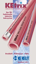
Chilled waterconditioning (PN10)Impermeabilityto oxygen<strong>The</strong> NONOX ® processPipe systems for chilled water coolingsystems (down to +2°C)Pipe systems for brine refrigerationsystems (down to –30°C)Advantages● Range of sizes: d20 – 160● Resistant to impact at – 30°C● Resistant to any concentration ofglycol brines● Oxygen barrier (NONOX ®process)● Resistant to corrosion even whenthe temperature unintentionally dropsbelow the dew point and at theaggressive temperature of 0°C.Drinking watermax.temp: 30°C PN10max.temp: 40°C PN16Advantages● Highly secure welded joint(safety factor > 3)● Tools, machines, and welding timessimilar to KELEN ® pipe system● Resistant to chemicals, water particlesand pressure hammer, even at lowtemperatures● Resistant to corrosion even in placeswhere unwanted condensation hasformed<strong>The</strong> alternative pipesystem<strong>The</strong> polymerKEtrix ® is made of CRYOLEN ® ,a PP-based polyolefine blend.Properties:Density 0,9 g/cm 3Tensile strength: 40 N/mm 2Elongation at tear: 800 %E-module (20°C): 1500 N/mm 2Heat conductivity: 0,23 W/m °CSpec. thermal expansion: 0,14 mm/m °CResistance to impact:– 30° CCompressed airtechnology (PN16)Compressed air has become indispensablefor the manufacturing sector and is used forthe following tasks:● Driving medium for tools● Pneumatic control systems● Driving medium for regulator fittings● Air purification at the workplaceAdvantages● Range of sizes: d20 – 110● High chemical resistance tocompressor oils● No corrosion and therefore novariation in the quality of thecompressed air<strong>The</strong> molecular structure of the polymersmeans that small amounts gases diffusethrough the material at different rates.<strong>The</strong> problem is well-known:● Carbonated drinks should not loseany CO 2● Many foods need to be protected fromthe effects of O 2 (fats, oils, milk cheese,meat…)● On the other hand aromas should notescape (coffee, jam, vegetables….)● Sheets act as water vapour barriers inbuildings Pipes in water circulationsystems must not allow oxygen todiffuse through the pipe as this willattack the metal components and causethe following problems:– Corrosion (Iron, steel)– Incrustation– Blockages– Malfunctioning– Expensive repairsIn general these problems are solvedby using composite materials:A combination of plastic material with othermaterials which provide strength or a barrierto oxygen diffusion E.g.– EVOH to prevent O 2 diffusion– Fluorine polymers to prevent H 2 O vapour– PA to prevent diffusion of oils and fuels– Metal to prevent the loss of aromaKE KELIT has developed a newpatented process:<strong>The</strong> structure of the polymer alloy makesit possible to close the ”molecular pores”by means of a ”redox” treatment. O 2 moleculescan no longer diffuse through thematerial.<strong>The</strong> resultKEtrix ® pipes, which are madecompletely of plastic are impermeableto oxygen when thewall thicknessis a minimum of 3,7 mm.<strong>The</strong> material was tested to ÖNORM B5157according to the zinc absorption method.Test reports by the TGM institute in Viennashowed the following results:Max. diffusiondefined by standard: 0,1 mg O 2 /d.m 3Result for <strong>Ke</strong>trix: < 0,005 mg O 2 /d.m 3A separate catalogue is available for the KEtrix ® pipe system!6 7
Drinking waterproblemsCorrosion● <strong>The</strong> concentration of ions in drinkingwater is increasing and consequentlythe risk of using metal pipes:Chlorides: attack stainless steelSulphates: attack galvanised steelNitrates: attack copper● Ever more problematic sourcesof water reserves have to be tappedfor the supply of drinking water● Acid rain reduces the pH value ofsurface and spring water to criticallevels below 7 (=neutral).External corrosion occurs as a resultof new building and insulation materialsand new installation methods.● Disinfectants (chlorine, ozone)attack copper in particular. PoisonousCu ions are released into the water!Incrustation● Hard water causes incrustation onthe inside walls of metal materials.<strong>The</strong> consequences:● Higher pressure losses● Reduced flow● Blockages● Expensive repair work● Time-consuming renovation● Disruptions in the water supplyA secure supply ofdrinking water is anessential factor fora high quality of lifeInternal corrosion - CuExternal corrosion - SteelCalcite depositsOperating conditionsPN20 = 20°C/20 bar; 70°C/8 barPN16 = 20°C/16 bar; 60°C/8 barPN10 = 20°C/10 bar;<strong>The</strong> solutionKELENdrinking waterpipe systemPlastics are not”replacement materials”.When chosen and appliedcorrectly they oftenprovide the bettersolution for a definedproblem.Sometimes eventhe only one<strong>The</strong> Result<strong>The</strong> KELEN pipe system has manyadvantages. Ideal for hot andcold water installations for bothnew projects and renovation.● Pressure ratings:PN10, PN16 and PN20● Cold water: d20 – d160 mmHot water: d20 – d110 mm● Resistant to internal and externalcorrosion caused by ions in thewater or chemicals on the site● No crystallisation points for limedeposits● Secure joint technology whichrequires no additional materials.● Conforms to hygiene regulationsand approved for transportingfoodstuff● Low pressure losses as a resultof smooth bore● Low noise level● Resistant to high temperaturesand pressure● Low thermal conductivitycomparison of λ-values:KELEN0,24 W/m°CCopper 320,00 W/m°CCast iron/steel 42,00 W/m°C● Stringent testing and monitoring ofquality to international standards● Secure long-term performance● Pipes are insulated at the factoryand can be located behind the wall● Can be combined with KELOX-multilayerflexible pipe system”No morecorrosion in the3rd millennium”8 9
δ v Tensile strength in MPa<strong>The</strong> raw materials<strong>The</strong> long-life plastic<strong>The</strong> raw material is a polypropylenecopolymer (PP.R) with its typical qualitycharacteristics (DIN 8077, DIN 8078).Every material is subject to ageing.PP-R is no exception to this rule of nature.<strong>The</strong> ”long-term creep curves”, which aredetermined by temperature and stress,are proof of the long service life(see page 13 for operating conditions).Long-term creep curve DIN 807810Density: 0,91 g/cm 3Melting Point:~ 0° CTensile strength: 40 N/mm 2Elongation at tear: 800 %E-module (20°C): 900 N/mm 2Spec. heat 2 kJ/kg °CHeat conductivity: 0,24 W/m °CSpec. themal expansion: 0,15 mm/m °C● KELIT technology has madeKELEN pipes particularlyresistant to impact at –5°C.● Pipes and fittings are madeof the same raw material.<strong>The</strong> following formulais used to calculate thetensile stress:<strong>The</strong> expected servicelife can be read off thegraph.Metal adaptorfittingsSpecial care has been taken over thechoice and quality control of the metalthreads.Special quality criteria:● Dezincification resistant brass(MS 63, CZ 132) for all partstransporting water ensures highresistance against aggressive water.● A pore-free, chemically appliedmetal plating prevents stress corrosioncracking.● Metal parts which are not in contactwith the media are generally madeof metal-plated MS 58 brass.● Exceptional resistance to torsion forceand suitable for on-site conditions● Depth of the thread conforms toDIN 1692 for normal faucets<strong>The</strong> insulation (LX)Foam:● Cross-linked PE● 100% closed pore● Density:30 kg/m3● Heat conductivity (λ) at:40°: 0.038 W/m°C60°: 0.039 W/m°C● Water vapour permeabilityµ = 10,000(an effective vapour barrier)● Environment-friendly● (CFC- free foam)● Bubble structure to insulate againstnoise transmission● Strong enough to withstand siteconditions● Concealed pipe can be locatedelectronically● Insulation can be pushed back toallow room for the weldingProtective coating:High quality 5-layer composite madeof polyolefines and aluminiumTime in h >10 11
PP-R pipe systemKEO2 KELEN pipePN10d x sFlow rate L/m20 x 1,9 mm 0,2125 x 2,3 mm 0,3332 x 2,9 mm 0,5440 x 3,7 mm 0,8350 x 4,6 mm 1,3163 x 5,8 mm 2,0775 x 6,8 mm 2,9690 x 8,2 mm 4,25110 x 10,0 mm 6,36125 x 11,4 mm 8,20160 x 14,6 mm 13,52Dimensions: as specified by DIN 8077Colour: Grey. 3 co-extruded green <strong>line</strong>s(90° apart) help the plumber to align pipeand fitting.Standard length: 4 m,Other lengths can be produced on requestsubject to minimum order quantities!Application as specified:Cold waterPN10:20°/10 barSafety factor: <strong>The</strong> DIN standard takes accountof raw material properties and calculates a safetyfactor of 50% (SF=1.5) when deriving the operatingconditions given on the right:Operating pressure in relationto service life and operatingtemperatureTemperature Pressure Service life(*C) (bar) (years)20 10 5030 9 5040 8 50KEO2 KELEN pipePN16d x sFlow rate L/m20 x 2,8 mm 0,1625 x 3,5 mm 0,2532 x 4,4 mm 0,4240 x 5,5 mm 0,6650 x 6,9 mm 1,0363 x 8,6 mm 1,6575 x 10,3 mm 2,3290 x 12,3 mm 3,36110 x 15,1 mm 6,36Dimensions: as specified by DIN 8077Colour: Grey. 3 co-extruded <strong>blue</strong> <strong>line</strong>s(90° apart) help the plumber to align pipeand fitting.Standard length: 4 m,Other lengths can be produced on requestsubject to minimum order quantities!Application as specified:Hot and cold waterPN16:20°/16 bar60°/8 barSafety factor: <strong>The</strong> DIN standard takes accountof raw material properties and calculates a safetyfactor of 50% (SF=1.5) when deriving the operatingconditions given on the right:Temperature Pressure Service life(° C) (bar) (years)20 16 5040 12 5060 8 5070 6 25KEO2 KELEN pipePN20d x sFlow rate L/m20 x 3,4 mm 0,1425 x 4,2 mm 0,2232 x 5,4 mm 0,3540 x 6,7 mm 0,5650 x 8,3 mm 0,8863 x 10,5 mm 1,3975 x 12,5 mm 1,9690 x 15,0 mm 2,83110 x 18,3 mm 4,23Dimensions: as specified by DIN 8077Colour: Grey. 3 co-extruded red <strong>line</strong>s(90° apart) help the plumber to align pipeand fitting.Standard length: 4 m,Other lengths can be produced on requestsubject to minimum order quantities!Application as specified:Hot and cold waterPN20:20°/20 bar70°/8 barSafety factor: <strong>The</strong> DIN standard takes accountof raw material properties and calculates a safetyfactor of 25% (SF=1.5) when deriving the operatingconditions given on the right:Temperature Pressure Service life(° C) (bar) (years)20 20 5040 15 5060 10 5070 8 5080 6 2512 13
KELITALU Composite pipeKELEN-LX SENSOinsulated pipe systemKEO6 KELIT ALU Composite pipePN10d x sFlow rate L/m20 x 2,8 mm 0,1625 x 3,5 mm 0,2532 x 4,4 mm 0,4240 x 5,5 mm 0,6650 x 6,9 mm 1,0363 x 8,6 mm 1,6575 x 10,3 mm 2,3290 x 12,3 mm 3,36Colour: <strong>The</strong> PP-R medium pipe is colourless.<strong>The</strong> outside layer is azure <strong>blue</strong>.Standard length: 4 m.A perforated ALU layer is bonded to themedium pipe by a coupling agent.This bonding reduces the expansionconsiderably.Pressure ratingTypeInsulation thicknessSizePN10KE02-LX44 mmd 20 x 1,9 mmd 25 x 2,3 mmd 32 x 2,8 mmPressure rating PN16 PN20Type KE08-LX4/LX9 KE00-LX4/LX9Insulation thickness 4 mm und 9 mm 4 mm und 9 mmSize d 20 x 2,8 mm d 20 x 3,4 mmd 25 x 3,5 mmd 25 x 4,2 mmd 32 x 4,4 mmd 32 x 5,4 mmOperating pressure in relation toservice life and temperatureOperating conditions as specified:Cold water 20°– 20 barHot water 70°– 8 barSafety factor: As a result of its higherresistance to temperature and pressurea PN16 ALU composite pipe can withstandthe same operating conditions as a standardKELEN PN20 pipe.Temperature Pressure Service life(° C) (bar) (years)20 20 5040 15 5060 10 5070 8 5080 6 25Length of pipe:Insulation:4 mPipe is covered inPE foam on theextruder <strong>line</strong>Insulation thickness: standard 4 mmand 9 mmProtective covering: HDPE <strong>line</strong>n bound fabricand viscoplastic polymeralloyTracing the pipe: SENSO layer makesit possible to traceconcealed pipeAdvantages● Enormous time savings● Cost savings● As a result of its elasticity theinsulation can be pulled backfrom the welding area● <strong>The</strong> ends of the pipes are protectedfrom damage and dirt● Prevents noise transmissionof concealed pipes14 15
<strong>The</strong> effectDrinking water pipes made of PP-R arewinning an ever bigger share of the worldmarket as the best possible alternative tometal pipes which are subject to corrosion.<strong>The</strong> appropriate institutions (DIN,CEN, ISO)lay down the minimum standards.KE KELIT does more than merely meetthe minimum standards. KE KELIT providessolutions to specific economic and technicalproblems such as the heat loss in pipingsystems.<strong>The</strong>re is a much lower heat loss throughKELEN hot water pipes than through metalpipes as a result of the vastly different heatconductivity of the materials(PP-R λ = 0.24 W/m°C; Copper λ= 320W/m°C; Steel λ= 42 W/m°C ).This fact alone is not sufficient for KE KELITwho have gone a step further.<strong>The</strong> d20, d25 and d32 pipes are pre-insulatedat the factory with either 4 mm or 9 mmof a special insulation (LEXEL=LX) againstheat loss.<strong>The</strong> results are remarkable:<strong>The</strong> potential savings<strong>The</strong> difference between the heat lossthrough non-insulated and insulatedKELEN pipes over the period of a yearshows that there is a remarkable potentialfor savings.ExampleComparison of a hotel room installationwith and without LX 4 insulation:2.7 m Riser d32 (installed in shaft)6.0 m Distributor pipe (embedded inconcrete)8.0 m Circulation pipe (embedded inmortar)Operating conditions:Hot water temperature: 60°CAverage room temperature: 25°CSystem in constant operation 365 daysper year: t 2Hot water requirement: 2 hours/day: t 1Source of energy: ElectricityHeat loss Q R (W/m)Annual heat loss (W)<strong>The</strong> following formula is used to calculate the heat loss:Amortisation calculation<strong>The</strong> heat loss calculated above must be compensatedby the permanent supply of extraenergy. Depending on the source of energy(electricity, oil, gas or geothermic energy)the costs will increase considerably.Example1KWh of electricity: e 0.06 – 0.151KWh of oil/gas: e 0.04 – 0.08If we assume that the average energycost is e 0.075/KWh then the reductionin heat loss of 297 KWh by installing theinsulated LX4 pipe will provide savingsamounting to: e 22.28 /year.By comparing the costsyou can make the followingconclusions:● <strong>The</strong> extra costs of the insulationis re-paid within WEEKS.● <strong>The</strong> total cost of the piping andthe insulation is re-paid withina few MONTHS● This represents a rate of returnwhich cannot be matched byany other form of investmentor shares.Blue <strong>line</strong> = <strong>blue</strong> chip = secure tip16 17
<strong>The</strong> six ways ofjoining the pipesA wide range of safe and secure methodsfor joining the pipes is essential for a pipesystem.KE KELIT has a comprehensive range offittings for each method of joining.1. Polyfusion weldingPrinciple:Fusion welding occurs when alarge area of the outside ofthe pipe and the inside of thesocket are welded togetherA wide range of weldingfittings is availableSizes: d20 – d110All KELEN polyfusion fittings fromd20 to d110 are rated PN20.<strong>The</strong>y can be used for welding topipes of all pressure ratings.Advantages● Pipe and fitting are madeof the same material.No additional materialsare required.● Welded joints are not aweak point in the system● Pipe can only enter thefitting after they havebeen heated on thewelding machine(important safety feature)● <strong>The</strong> weld does not causea reduction in the flow atthe joint.3. Threaded adaptor fittingsSizes:d20 x 1/2”– d75 x 2 1/2”<strong>The</strong> threads conform toDIN 2999 and are made ofdezincification resistant brass(MS63-CZ 132). <strong>The</strong>y are metalplatedto protect against stresscorrosion cracking. Male andfemale threads are available asboth straight and elbow fittings.4. Flange connectionSizes: d20–d160<strong>The</strong> solution for flangedfittingsBacking ring conforms topipe sizesFusion welding: d20 – d125Butt welding: d1605. Detachable union fittingsSizes: d20 x 1/2”– d90 x 3”3 types:Advantages● Wide range of fittingsFemale thread is astraight thread● Male thread is taperedand roughened● Thread is firmly anchoredin the fittingHigh resistance to twistingstrainAdvantages● Can be detached atany time● Elastic EPDM seal● Dimensions conformto DIN 2501-PN16Advantages● Detachable fittings● Elastic EPDM fittings● KE57 fitting forconnecting to appliances2. Butt weldingPrinciple:After the end of the pipe has been cutflat the face of the pipe and fitting aresimultaneously heated to meltingtemperature. <strong>The</strong>y are then pressedtogether under pressure until thematerial has cooled.Advantages● Pipe and fitting are madeof the same material. Noadditional materials arerequired.● Welded joints are not aweak point in the system.● <strong>The</strong> weld does not causea reduction in the flow atthe jointSizes: d125–d160KE55-PPR-male thread KE56-PPR-PPR KE57-PPR-male thread6. Electrofusion weldingSizes: d20–d160KELIT E-welding sockets maybe considered for welding inconfined areas.Advantages● Repair socket forconfined areas● Welding machineavailable at KE KELIT● Each fitting is packagedindividuallyInstruction sheet andcleaning tissue areenclosed18 19
KELEN ® polyfusionwelding with thehand welding machine1.11. <strong>The</strong> pipes and fittings are joined bypolyfusion welding at 260°C. <strong>The</strong> weldingmachines and tools are self-regulating.Just connect to the electricity supply (230V)and wait:<strong>The</strong> red light indicates that the machine isconnected to the electricity supply.When the green light goes out the weldingtemperature has been reached.Work can begin.Measure the length of piperequired and cut the pipe with the appropriatepipe cutter (up to d40 with the pipeshears;up to d110 with the wheel pipe cutter).1.1 Before welding the KELIT ALUcomposite pipe sufficient aluminiummust be removed by the peeler to allowthe pipe to be welded to the full depth ofthe socket. <strong>The</strong> colourless medium pipe isclearly distinctive from the protectivecovering.Important: <strong>The</strong>re should be no aluminiumin the welding area. Make a visual checkbefore welding!<strong>The</strong> pipe can then be welded to the fittingsin the same way as the standard KELENpipe.2.2 <strong>The</strong> heating time (see table) beginswhen the full insertion depth of the pipeand the whole of the socket in the fittinghave been pushed on to the welding tools.2.3 <strong>The</strong> heating time varies according tothe pipe size (see table).Once the heating time has elapsed pushthe pipe and fitting together smoothly andevenly without delay. <strong>The</strong> result is a homogeneousand strong joint.2.4 Three <strong>line</strong>s on the pipe (90° apart)act as a guide for making a straight joint.2.5 <strong>The</strong> position of the fitting can beadjusted for a few seconds immediatelyafter the pipe and fitting have been joined.A short time later (see table) the jointis capable of withstanding operatingconditions.3. <strong>The</strong> low weight and high flexibilityof the material makes it possible to weldwhole sections of the piping at the workbench. Take advantage of this and savea lot of time.4. Make sure that any joints which stillneed to made in the wall are positioned sothat they are accessible with the weldingmachine.Welding times4.2.1d160:<strong>The</strong> welding procedure2. Ensure that the surface of the pipesare clean and free of grease2.1 Measure the depth of the socketand mark the insertion depth on the pipeaccordingly.5. <strong>The</strong> distance between the draw-offpoints at the wall can be set (for all commoninstallations) both horizontally andvertically using a template equipped witha spirit level.6. <strong>The</strong> pipes should be insulated accordingto the relevant national standards.5.20 21
Polyfusion weldingof KELEN ® -LX pipeswith the handwelding machineImportant!<strong>The</strong> bubble structure and the goodgrip make it easy to pull back theinsulation.Pressing the insulation to the pipecan prevent the insulation fromslipping back<strong>The</strong> following guide<strong>line</strong>s apply forall pre-insulated KELEN-LX pipes.Point 1. is identical to the instructionsfor non-insulated pipes on pages 20 and 212. Exposing the ends of the pipes2.1 For short lengths of pipes the weldingarea can be exposed by simultaneouslysupporting the pipe on a bench andpushing back the insulation.2.2 For longer lengths of pipes one handholds the pipe while the other hand pushesback the insulation2.3 For especially long lengths of pipe itmay be easier if the hands are crossed over.2.4 It is NOT necessary to cut the insulation.3. <strong>The</strong> welding procedure and weldingtimes are identical to point 2. of theinstructions for the standard KELEN pipe.4. SENSO pipe detection<strong>The</strong> SENSO properties of the LXinsulation allows the system to be locatedup to a maximum depth of 80 mm in thewall.4.1 Follow the instructions for the detector.4.2 Locate where the pipe is running bothhorizontally and vertically within a radiusof 50 cm from the place where the hole isgoing to be drilled.Welding KELEN ®saddle fittings1. <strong>The</strong> surface of the pipes and saddlefittings should be free of grease, cleanand dry.2. A hole is drilled in the pipe usinga 24 mm saddle drill.3. <strong>The</strong> pipe wall and the saddle fittingare heated simultaneously with the speciallydesigned welding tools for approx. 30 sec.4. Once the heating time is over the saddlefitting is pushed into the pipe wall immediately(do not twist!) and pressed for approx.30 sec. <strong>The</strong> melting of both the pipe walland the pipe surface ensures a stronghomogenous joint. After approx. 10 minutesthe joint can be subjected to operatingconditions.22 23
Table weldingmachine1. Screw the required heatingelements to the welding plate.<strong>The</strong> length of the heating element variesaccording to the size of the pipe and thesection of pipe to be welded.2. One side of the pipe clamps canbe used for small pipe sizes (d20 – d40).For larger sizes (d50 – d90) the clampsshould be turned around.3. <strong>The</strong> same principle applies for thefittings clamps.See pages 20 and 21 for instructionson preparing pipes and fittings forwelding.4. Set the pipe diameter switch tothe required size. This switch regulatesthe length of the pipe that will be weldedinto the socket5. Spacing button.Press the button to fix the distancebetween the two sliding blocks which willenable the appropriate section of pipeand the complete socket of the fitting tobe heated on the welding elements.Note: <strong>The</strong> machine is available intwo sizes:Type 1: d20–90 mmType 2: d25–125 mm<strong>The</strong> welding procedure:1. Fix the fitting in the clamp and thefitting holder. Ensure that the face of thefitting is flat against the clamp.1.1 Put the pipe in the pipe clamp.Do not tighten the clamp.1.2 Hold down the spacing button and movethe sliding blocks together using the handwheel until the pipe is touching the fitting orthe sliding blocks can no longer move1.3 Release the spacing button.Only now fix the pipe in the clamp.2. Move the sliding blocks apart andpull down the welding plate.2.1 Move the sliding blocks togetheruntil they are stopped by the lock2.2 When the heating time has elapsedmove the sliding blocks apart briskly andquickly remove the welding plate.3. Push the sliding blocks togetherbriskly until the pipe diameter switch catches.3.1 Never cool the welded joint abruptly.After a while loosen the clamp and thefinished joint can be removed from themachine.3.2 Once the cooling time has elapsedthe joint can be subjected to operatingconditions.24 25
Overhead weldingmachineIt is recommended to use theoverhead welding machine forexposed piping in confined areas(d50–d110).1. Fix the pipe clamps to a pipe thathas already been installed. <strong>The</strong> machine willhang at the end of the pipe.1.1 To provide extra support the pipe shouldbe clamped close to a pipe bracket1.2 A pole can be placed under the centreof gravity to support the machine if necessary.1.3 <strong>The</strong> pipe should protrude far enoughout of the pipe clamp to ensure that the pipecan be fully welded into the socket of thefitting but also allow enough space for thewelding plate.<strong>The</strong> space between the pipe and thefitting when the sliding block has beencompletely rolled back should beapprox. 100 to 150 mm.2. Put the fitting in the clamp and supportthe fitting with the fixing elbow. <strong>The</strong> fittingmust have sufficient room to move sidewaysso that the whole of the socket can be welded.3. Put the welding plate between the pipeand fitting. Turn the hand wheel to move thepipe and fitting on to the welding tools. Heatthe pipe and fitting.3.1 When the heating time is over removethe welding plate and push the pipe and fittingtogether briskly to weld the joint.3.2 When the cooling time is over the jointcan be subjected to operating conditions.28 29
Special plumbingsolutionsPolyfusion welding of the KELEN ® pipesystem is both secure and quick. A lot moretime is spent fixing the pipes and joiningto the faucets. <strong>The</strong> are some practicalsolutions which can make the job easier forthe plumber.Method of installation:● Partition wall installation● Brick wall installation● Installation in front of the wallK85 KELEN ®Joining set<strong>The</strong> set is used for fixing the outlets atthe wall and consists of the followingitems:● Metal plate (2.5 mm thick)● Wall brackets: KE83 d20 ord25 x 1/2” and double peg fitting● Sound insulation caps● Elastomer sound insulation pads● Plastic stoppers● Pegs and screws● Connection to d50 siphon trap andd30 rubber nipple is optional● Set available for single outlet orfor double outlet (80–100 mmor 150 mm)K85H KELEN ®Fixing plate forpartition wallsA special system is required for installationsin front of the wall and in partition walls.By cutting the K85H plate to the requiredlength it is possible to arrange the plate sothat the fittings are fixed in the requiredpositions.<strong>The</strong> fitting is fixed to the double peg fittingK86D behind the plate.For special applications the metalplate is available separately(ref: K85A)K85K sound insulation cap for KE83.<strong>The</strong> cap does not fix the fitting.A special solution is required for fixingthe fitting and the cap.K86 HA Faucet plate<strong>The</strong> faucet connection fitting KE83HAhas the following properties:● No transmission of energyto the plaster board● <strong>The</strong> holes are octagonal to preventtwisting of the fitting● <strong>The</strong> torque force on both fittingsis balanced by the fixing plate● <strong>The</strong> octagonal holes mean that thefitting can be fixed in every position● Sound insulating pad is completelycovered with PE soft foam32 33
Pipe sizingPressure losses inKELEN ® pipes<strong>The</strong> total pressure loss (∆p) in the KELEN ® pipesystem is calculated by multiplying the frictionloss (R) by the length of the piping (l) plus thesum (∑) of the friction losses for the individualfittings (Z).Total pressure loss ∆p∆p = (I · R + ∑Z) in Pa<strong>The</strong> choice of pipe size for the watersupply is dependent on the followingfactors:● <strong>The</strong> available water pressure● Geodetic difference in height● Pressure losses through systemcomponents● Minimum flow pressure through faucets● Pressure losses in the pipes● <strong>The</strong> individual pressure losses of thefittings● Type, number and simultaneous useof the draw-off points● Flow velocityNote:For the purpose of pipe sizing it is assumedthat that there will be no reduction in theinternal diameter caused by incrustationsince the surface structure of the pipe isamorphous and the surface roughness ofthe pipe is minimal (0,007).Maximum flow velocityaccording to DIN 1988Maximum design flowvelocity for a given pipe run ≤ 15 minm/s>15 minm/sService pipes 2 2Supply mains:pipe runs with low head lossin-<strong>line</strong> valves(ζ < 2.5) 5 2In-<strong>line</strong> valveswith greaterloss factor 2,5 2Fitting Symbol CoefficientζGSGuide<strong>line</strong>s for pipesizing (DIN 1988/3)1. Determine the design flow rateand minimum flow pressure for allthe draw-off fittings<strong>The</strong> design flow rate V R is derived fromthe draw-off fitting flow rate. <strong>The</strong> tablebelow gives guide<strong>line</strong> values for the designflow rate of common types of fittings andappliances. <strong>The</strong> design flow rate V R may bedetermined as a mean value using thefollowing equation.V˙R = V˙min + V˙max22. Determine total flow rates andassign to pipe runs<strong>The</strong> design flow rates for all draw-off pointsshall be added, starting at the draw-offpoint furthest from the water main and endingat the water main, and the total flowrates so obtained assigned to the pipe runsconsidered, each run extending from thefitting where the total flow rate or pipe diameterchanges until the next fitting.At the junction of the cold water pipefeeding the water heater with thepipe that branches off, the total flowrate comprises that of the cold andhot water side.3. Use of total flow rate/peakflow rate<strong>The</strong> design flow rate of all draw-off pointsshall be included in the design of watersupply system, adding the flow rate of thedraw-off points for which continuous use isto be assumed to the peak flow rate of theother draw-off points(continuous use being defined as use lastingmore than 15 minutes).Assumptions regarding simultaneous demandare to be based on the type of buildingor its occupation (e.g. residential buildingor communal facility).Normally it may be assumed that not alldraw-off fittings are fully open at thesame time.<strong>The</strong> conversion curves for the differentapplications are shown on pages40 and 41.4. Determination of pipe diameterDetermine the pipe size, pressure loss andflow velocity (see tables on pages37 to 39).5. Evaluation of head loss in termsof available pressure<strong>The</strong> head loss shall be almost equal tobut not greater than the availabletotal head loss.34 35
Guide<strong>line</strong>s for pipesizing (DIN 1988/3)6. Minimum flow pressure anddesign flow rate for typical draw-offpoints and appliances.Pressure lossesPN10<strong>The</strong> method for calculating the pressureloss of the individual fittings is describedon page 34.<strong>The</strong> pressure losses are calculated accordingto the Nikuradse formula:Surface roughness: 0,007 mmMinimum Type of draw-off fitting Design flow rateflow or appliancepressureMixed water*) Cold water only˙VR ˙VR ˙VRbar cold l/s hot l/s l/sTaps0,5 without jet regulator DN 15 – – 0,300,5 DN 20 – – 0,500,5 DN 25 – – 1,001,0 with jet regulator DN 10 – – 0,151,0 DN 15 – – 0,151,0 Shower headsDN 15 0,10 0,10 0,201,0 Flushing valvesfor urinals DN 15 – – 0,301,0 Domesticdishwasher DN 15 – – 0,151,0 Domesticwashing machine DN 15 – – 0,25Mixing valves for1,0 showers DN 15 0,15 0,15 –1,0 baths DN 15 0,15 0,15 –1,0 kitchen sinks DN 15 0,07 0,07 –1,0 wash basins DN 15 0,07 0,07 –1,0 sitz baths DN 15 0,07 0,07 –1,0 Mixing valves DN 20 0,30 0,30 –0,5 DIN 19542flushing cistern DN 15 – – 0,13*) <strong>The</strong> values specified are based on atemperature of 15°C for cold water and60°C for hot water.Note:For any outlets or apparatus not includedabove or similar to the above with adifferent flow rate please follow themanufacturers instructions regarding thesizing of the pipes.36 37
Pressure lossesPN16<strong>The</strong> pressure losses are calculated accordingto the Nikuradse formula:Pressure lossesPN20<strong>The</strong> pressure losses are calculated accordingto the Nikuradse formula:<strong>The</strong> method for calculating the pressureloss of the individual fittings is describedon page 34.Surface roughness: 0,007 mm<strong>The</strong> method for calculating the pressureloss of the individual fittings is describedon page 34.Surface roughness: 0,007 mm38 39
Excerpt fromDIN 1988/3Excerpt fromDIN 1988/3Residential buildingsAn additional wash basin, sitz bath, WC,urinal and bath tub (in addition to thebath tub) need not be allowed for in determiningthe total flow rate if it may be assumedthat the level of simultaneous usewill not be increased by the use of theseappliances.Schools<strong>The</strong> peak flow rate is deemed to be equalto the design flow rate where ∑ V R doesnot exceed 1,5 l/s.Special caseIf the system is equipped with draw-offfittings with a design flow rate of morethan V˙R ≥ 0,5 l/s then, where the totalflow rate is between 0,5 l/s and1,0 l/s the peak flow rate shall bedeemed to be equal to the total flow rate.If the total flow rate is ≥ 1,0 l/s or morecurve B shall be used.Hotels, department stores andhospitalsIf the system is equipped with draw-offfittings with a design flow rate of morethan ˙VR ≥ 0,5 l/s then, where the totalflow rate is ≤ 1,0 l/s the peak flow rateshall be deemed to be equal to the totalflow rate. If the total flow rate is>1,0 l/s and ≤ 20 l/s curve K(equation: ˙VS =(∑˙VR)0,366 in l/s) isused for calculating the peak flow rate.Other special buildings, commercialand industrial premisesParticular considerations must be givento the extent to which simultaneousdemand is to be assumed for water supplysystems on commercial and tradepremises. <strong>The</strong> total flow rate is determinedin consultation with the operator of thesystem.40 41
Expansion behaviourof KELEN ® pipesLinear heat expansionUnder heat conditions all materialsincrease in volume and/or lengthaccording to the following formula:Calculation of the <strong>line</strong>ar expansion:∆ l = I · ∆ t · α<strong>The</strong> <strong>line</strong>ar expansion is determinedby the length of the pipe, the increasin temperature and the coefficientof expansion.It is not determined by the diameterof the pipeComparison ofmaterialsCoefficient of E-module 60°expansionα = mm/m°C N/mm 2Galv. steel 0,012 220000Stainless steel 0,015 200000Copper 0,016 130000KELIT Alu comp.* 0,035* 3500PVC 0,080 1100KELEN 0,150 300PEX 0,175 540* α d63 and above = 0,050Expansion arm forexposed pipingCompensation must be made for theexpansion of KELEN pipes under heatconditions.Even if the rise in temperature is only fora short time sufficient compensation mustbe made for this temperature differenceCompensation is always made betweentwo fixed points or between a fixed pointand a change in direction of the piping(expansion arm).Calculation of the expansion arm:MS = 20 · d · ∆ l20 = Coefficient for KELENMS = Minmum length of theexpansion arm (mm)Length of pipe which branches offat 90° from the main pipe to thenext fixed pointExample:d50 mm pipe runs over a length of 15 m∆ t = 35°CQuestion: How long does the expansionarm have to be to compensate for theexpansion?∆ I = 15 · 35 · 0.15∆ I = 79 mm expansionMS = 20 · 50 · 79MS = 1256 mm expansion armDifference in temperature ∆tMinimum length of expansion arm (mm)Heat expansion chart (unhindered <strong>line</strong>ar expansion) ∆ lThis means that when heatedKELEN ® will expand more than metalmaterials if the expansion isunhindered.42 43
Force of heatexpansion<strong>The</strong> force of <strong>line</strong>ar expansion is differentfor each material. <strong>The</strong> specific force of heatexpansion is calculated according to thefollowing formula:F t = E · A · α · Δ t1000<strong>The</strong> force of heat expansion isdependant on the dimension of thepipe and the change in temperaturebut not on the length of piping.An important factor is the rigidity of thematerial (E-module)Comparison of the materials:If unhindered KELEN ® pipes willexpand more than metal materialsunder the influence of heat. <strong>The</strong>force of heat expansion, however,is much smaller!E-module (E) in N/mm 2<strong>The</strong> E-module of PP-R (like any otherplastic) is dependant on the temperature(see graph below)> Temperature: < E-module< Temperature: > E-moduleAs the temperature increases the E-moduledecreases.E-module of PP-R in relation to theoperating temperature t m1000900800700600500400300200180010 20 30 40 50 60 70 80Temperature t m in °C >Example:Length of piping:l = 50 mTemperature during installation: t v = 20°CMedium temperature: t m = 60°CDifference in temperature: d l = 40°CPractical solutionsfor compensatingexpansion<strong>The</strong> following methods can be used tocontrol the <strong>line</strong>ar expansion and the forceof expansion:l Piping that is embedded in thewall or the floor is prevented fromexpansion by frictional force.No extra measures are required.l Compensation must be madefor expansion of exposed pipingl Even if the rise in temperature is only fora short time sufficient compensation mustbe made for this temperature difference(see pages 42, 43, 46 and 47)l Every change in temperature will exerta force.> An expansion force will occur whenthe temperature rises.< A shrinking force will occur whenthe temperature falls.l Pipe channels may be used to increasethe stability of the pipe.<strong>The</strong> expansion is reduced to the samevalue as steel pipes.l <strong>The</strong> strength of the fixed points shouldbe sufficient to compensate the expansionforce.l <strong>The</strong> specific expansion can be minimised byinstalling the KELIT ALU composite pipe(d20 – d90), especially on long pipe<strong>line</strong>s.This pipe reduces the expansion byapprox. 75%.Dimension Linear expansion Force of expansion(F t )27,3 x 3,2 Galvanised steel26,9 x 2,0 Stainless steel28 x 1,2 Copper25 x 3,5 KELIT Alu Composite25 585 N18 774 N8 406 N1 248 N<strong>The</strong> force of expansion can be calculatedfor every installation. However, in generalthe force is just a fraction of theforce which occurs with metal materials.Suppliers of pipe clamps and brackets knowthe properties of the materials and offer arange of solutions.25 x 2,9 PVC25 x 3,5 KELEN ® 25 x 3,5 PEX/VPE771 N426 N894 N0 100 200 300 400 mm44 45
Installing KELEN ®1. Installing the pipes in the shaftIn practise the main risers can expand and contract laterallyin the shaft between two floors if a fixed point is located nextto the pipe that branches off from the main pipe. <strong>The</strong> distancebetween two fixed points should not exceed 3 m. Other methodscan be used to accommodate expansion such as an expansionarm in the pipe branching off from the riser.2. Embedding the pipePiping that is embedded in the wall, floor screed etc. …is prevented from <strong>line</strong>ar expansion. <strong>The</strong> material can absorbthe pressure and tensile stress without causing any damage.If the pipes are insulated then the insulation material providesfurther room for expansion.3. Exposed piping3.1 Preventing expansion bymechanical restraint d20–d50For aesthetic reasons KELEN ALU pipesare often preferred for exposed pipesbelow d63. Greater stability can beobtained by installing the pipes in steelchannels.In order to achieve this stability all of thepipes must be supported by pipe channelsand all of the brackets must be fastenedtightly to the pipe to make them fixedpoints. In addition the channels are fixedto the pipe (e.g. using cable ties) exceptfor the sizes d20, d25 and d32 as thechannels for these sizes are self-locking.This method reduces the <strong>line</strong>ar expansionto the same amount as steel.Guide<strong>line</strong>s for distance between pipesupport points<strong>The</strong> distances between the support points given below (in cm)prevent KELEN ® pipes from sagging when they are filled withwater and there are NO pipe channels.3.2 Expansion loops d 63–110All changes in the direction of the pipecan be used to accommodate the <strong>line</strong>arexpansion. In some cases an expansionloop will be necessary.<strong>The</strong> fixed points are arranged so that thepiping is divided into sections and theexpansion force can be guided in thedesired direction. See pages 42 –45 forthe calculations of the length of theexpansion arm.d PN 1O PN 16 PN 20 ALU PN 20mm 20°C 20°C 60°C 20°C 60°C 20°C 60°C20 70 75 60 80 65 120 10025 75 80 70 85 75 130 11032 90 95 80 100 85 150 13040 100 105 90 110 95 170 15050 115 120 100 125 105 180 16063 130 135 110 140 120 195 18075 150 160 130 170 150 205 19090 185 195 150 205 170 215 200110 195 205 160 215 180 – –125 205 – – – – – –160 220 – – – – – –minimum (mm)2 · Δ l + 150 mmMS46
Pressure testingfor drinking watersystemsKE KELIT recommends pressure testing toDIN 1988/2 for plastic pipes as statedbelow.As a result of the material properties ofplastic pipes the pipe will expand duringthe pressure testing. <strong>The</strong> pressure testingis split into a preliminary test and a maintest. <strong>The</strong> preliminary test is sufficient forsmall sections of the piping such asconnecting pipes and distributing pipesin the wet rooms.a) Preparation1. After the pipes have been installedand before they are concealed thepiping is filled with water and any airremoved.2. If possible the pump should be placedat the lowest point in the system3. <strong>The</strong> manometer should be capableof reading changes in pressure of0,1 bar and should be placed at thelowest point of the section of pipingbeing tested.b) Preliminary testing<strong>The</strong> test pressure is equal to the maximumoperating pressure of the system plus 5bar (minimum: 15 bar). <strong>The</strong> test pressuremust be built up over a period of 30minutes. Within the 30 minutes thepressure should be re-adjusted 2 times(each time 10 minutes apart). After afurther period of 30 minutes underpressure testing there should be no leaksand the drop in pressure should notexceed 0,6 bar.c) Main testing<strong>The</strong> main testing should be carried outimmediately after the preliminary testing.<strong>The</strong> duration of the test is 2 hours. <strong>The</strong>drop in pressure between the end of thepreliminary testing and the end of the 2hour main test must not exceed 0,2 bar.After the pressure testing has beencompleted we recommend issuing aconfirmed report.Please note:l Fluctuations in the temperaturemay alter the test pressurel Every pressure test is anassessment of the current stateof the system and is noguarantee against any mistakesmade during installation.Drinking water – Pressure test reportLocation: –––––––––––––––––––––––––––––––––––––––––––––––––––––––––––––––––––––––––––––––––––––––––––––––––––Project: –––––––––––––––––––––––––––––––––––––––––––––––––––––––––––––––––––––––––––––––––––––––––––––––––––Length of piping:Length of piping:Length of piping:Length of piping:Length of piping:Length of piping:Test: Yes NoVisual check:Test pressure:Preliminary test:Testing time = 60 min.Pressure after 1 hour:Main test:Testing time = 120 min.Pressure after 2 hoursLocation of highest outlet:Ambient temperature:<strong>The</strong> piping is free of leaks:d 16 _ _________ md 20 _ _________ md 25 _ _________ md 32 _ _________ md 40 _ _________ md 50 _ _________ mLength of piping:Length of piping:Length of piping:Length of piping:Length of piping:Length of piping:❏❏___________ bar (minimum: 15 bar)___________ bar (max. pressure drop: ≤ 0,6 bar)___________ bar (max. pressure drop: ≤ 0,2 bar)___________ m above the manometer___________ ° CComplaints: – ––––––––––––––––––––––––––––––––––––––––––––––––❏d 63 _ _________ md 75 _ _________ md 90 _ _________ md 110 _________ md 125 _________ md 160 _________ m– ––––––––––––––––––––––––––––––––––––––––––––––––ConfirmationPerson in charge: _ _______________________________________________Date: ______________________ Time: from ____________ to _ ____________Client: _ ______________________________________________________signature/stamp48 49
Technical rulesfor drinking waterAssuming that the design and installationhas been done professionally werecommend that the following guide<strong>line</strong>sare followed.RinsingAfter pressure testing the drinking waterpipes must be rinsed.Depending on the size of the installationand how the piping is run the systemshould be rinsed in sections from thebottom to the top.Each riser is rinsed in turn and the lengthof piping should not exceed 100 m.DIN 1988/2, table 10, specifies theminimum number of draw-off points thathave to be opened. Under normalcircumstances all draw-off points shouldbe opened. <strong>The</strong> rinsing time depends onthe length of piping and should not beless than 15 seconds for each metre ofpipe. <strong>The</strong> rinsing time at each draw-offpoint should be at least 2 minutes. Afterthe pipe has been rinsed for approx. 2minutes at the last draw-off point all thedraw-off points are closed in the reverseorder to which they were opened.DIN 1988/2Sound controlDIN 4109 recommends the followingmeasures:l Use low-sound faucetsl Avoid direct contact between pipesand other sound transmittingbodies when fixing the pipe.l Avoid high pressures and highflow velocitiesl Special measures should be takenfor sound sensitive areasl Cover with sound reducing insulationl KELEN LX pipes(4 mm or 9 mm insulation)<strong>The</strong> bubble structure of the insulationprovides excellent protection againstsound transmission.<strong>The</strong> high strength of the insulationcover provides a long termbarrier between the pipe and othersound transmitters.Largest nominal diameterof the distributing pipe DN 25 32 40 50 65 80 100Minimum flow through thecompletely full distributing pipe I/min 15 25 38 59 100 151 236Minimum number of draw-offpoints to be opened DN15 1 2 3 4 6 9 14Minimum flow and minimum number of draw-off points to be opened for rinsing ata minimum velocity of 0,5 m/soHeat insulation forpotable water pipesDrinking water pipes (cold)Cold water pipes need to be insulatedagainst warming and condensation.It must be ensured that the water qualityis not reduced as a result of the waterwarming.DIN 1988/2 specifies the minimuminsulation thickness for potable waterpipes when the medium temperature isassumed to be 10°C.Type of InstallationExposed pipework in an unheated room (e.g. cellar)Exposed pipework in an heated roomPipework underground with no adjacent hot water pipesPipework underground next to hot water pipesPipework in wall, riserPipework on concrete ceilingDrinking water pipes (hot)We recommend that hot water pipes areinsulated in accordance with DIN 1988/2.If there is no requirement for hot waterin circulation it is usually possible to dowithout insulation for pipes up to 25 mm.Even thin insulation reduces theheat loss considerably!See pages 16 and 17.Thickness of insulationmm4 KELEN LX-49 KELEN LX-94 KELEN LX-413 KELEN+Insulation4 KELEN LX-44 KELEN LX-450 51
Summary of theinstruction guide<strong>line</strong>s1.<strong>The</strong> KELEN ® pipesystem is made ofplastic and needs to betreated carefully toprevent shocks and impact on the pipeduring transportation, storage andinstallation.2.Protect the pipes,fittings andcomponents fromlengthy exposure todirect UV radiation from the sun.<strong>The</strong> usual time required for storage andinstallation will have no effect on thematerial as it is stabilised against UV raysbut the material is not resistant to long termUV exposure.3.<strong>The</strong> welding machinesare regulated tooperate at 260° C.Welding timesare based on an ambient temperatureof 20°C.If the ambient temperature changes thetime required to push the pipe and fittingon to the heating elements (before theheating time begins) may alter slightly.4.Any corrections to thealignment of pipe andfitting up to amaximum of 5 mustbe made during the welding procedure(see pages 18 – 25 for the permissibletime for adjustments). Any later correctionswill damage the joint.5.Do NOT screw anythreaded pipes or anycast iron fittings intothe female threads ofthe metal moulded fittings.Only join to faucets and components withstraight threads. <strong>The</strong> threaded joint canbe sealed by the usual methods (hemp,paste, tape …).Do not over twist the threads.6.<strong>The</strong> expansion ofKELEN ® pipes isclearly defined andmust be accounted forin the design and installation of the system.Please refer to pages 42– 47 regardingthe methods of accommodating theexpansion of exposed piping• KELIT Alu composite pipe (page 14)• Pipe channels (page 47)• Expansion loops (pages 42 and 43)For longer sections of piping the fixedpoints can be located in such a way thatthe system is split into expansion zones.Suppliers of pipe clamps and bracketsoffer a wide range of solutions.7.Avoid using heat tobend the pipes(it is possible to bendthe cold pipe to aradius of 8 x d). If the pipe has to be heatedthen only use hot air. Never heatthe pipe with a naked flame!Maximum temperature for bendingthe pipe: 140°C8.Try to make the jointsfor standard sectionsof piping at the workbench before they areinstalled. This saves timeand increases the security of the system.9.Once the system hasbeen installed itshould be subjected topressure testing.You can copy pages 48 and 49 of thecatalogue to make a test report.10.• A temperature of90°C for short periodsof time is NO problemfor KELEN. Highertemperatures over longerperiods of time should be avoided. <strong>The</strong>pipe system is suited for thermal disinfection.• <strong>The</strong> gradual or continual (max. 6 months)disinfection of the pipe system with chlorinedioxide, chlorine or ozone is only permittedfor the cold water system and after consultationwith KE KELIT.• Excessive concentrations are not onlythreatening to health they can also causepremature ageing of pipe systems.• Copper und copper ions have a destabilisingeffect and their presence in the systemshould be avoided.11.<strong>The</strong> followingprecautions can bemade to ensure thatthe maximumoperating temperature is not exceeded:• Monitor and regulate solar energystorage.• Check the electric connections to the hotwater storage before the system isoperated.• We recommend installing in the hotwater piping a mixer valve which isregulated by the boiler.12.In order to qualify forguarantee cover eachinstallation must useKELEN ® system partsonly.13.In order to install theKELEN® systemcorrectly a minimalamount ofexpenditure is required for tools For yourown security we recommend that you useand maintain the tried and trusted tools.14.If you are in doubt donot hesitate to consultour technicians.<strong>The</strong>re is not always aperfect solution but we can always help.52 53
Product range<strong>The</strong> KELEN ® pipe system is constantlybeing extended and updated to meet therequirements of the industry.Please refer to the current KELEN ® pricelist for the complete product range.<strong>The</strong> abbreviated references, e.gKE00 (= PN20 pipe) orKE30 (= tee), simplify the administration.Please refer to the KE numbers when youplace your order.On request and subject to minimumquantities and capacities we canmanufacture special types of fittings(e.g. 30° elbow).KE08 KELEN ® pipe PN16d s di L Weight Vmm mm mm m kg/m l/m20 2,8 14,4 4 0,15 0,1625 3,5 18,0 4 0,23 0,2532 4,4 23,2 4 0,37 0,4240 5,5 29,0 4 0,58 0,6650 6,9 36,2 4 0,90 1,0363 8,6 45,8 4 1,41 1,6575 10,3 54,4 4 2,01 2,3290 12,3 65,4 4 2,87 3,36110 15,1 79,8 4 4,30 5,00KE02 KELEN ® pipe PN10d s di L Weight Vmm mm mm m kg/m l/m20 1,9 16,2 4 0,11 0,2125 2,3 20,4 4 0,17 0,3332 2,9 26,2 4 0,27 0,5440 3,7 32,6 4 0,42 0,8350 4,6 40,8 4 0,66 1,3163 5,8 51,4 4 1,04 2,0775 6,8 61,4 4 1,41 2,9690 8,2 73,6 4 2,11 4,25110 10,0 90,0 4 3,01 6,36125 11,4 102,2 4 3,92 8,20160 14,6 130,8 4 6,35 13,52KE00 KELEN ® pipe PN20d s di L Weight Vmm mm mm m kg/m l/m20 3,4 13,2 4 0,17 0,1425 4,2 16,6 4 0,27 0,2232 5,4 21,2 4 0,43 0,3540 6,7 26,6 4 0,67 0,5650 8,3 33,4 4 1,04 0,8863 10,5 42,0 4 1,65 1,3975 12,5 50,0 4 2,34 1,9690 15,0 60,0 4 3,36 2,83110 18,3 73,4 4 5,01 4,23K06 KELIT-ALU composite pipe PN20d s di L Weight Vmm mm mm m kg/m l/m20 2,8 14,4 4 0,21 0,1625 3,5 18,0 4 0,32 0,2532 4,4 23,2 4 0,47 0,4240 5,5 29,0 4 0,70 0,6650 6,9 36,2 4 1,03 1,0363 8,6 45,8 4 1,60 1,6575 10,3 54,4 4 2,22 2,3290 12,3 65,4 4 3,15 3,3654 55
KE02-LX4 KELEN ® LX-SENSO pipe PN10d s di IS L Weight Vmm mm mm mm m kg/m l/m20 1,9 16,2 4 4 0,14 0,2125 2,3 20,4 4 4 0,20 0,3332 2,9 26,2 4 4 0,30 0,54Diagram for all KELEN LX-SENSO pipesKE08-LX4 KELEN ® LX-SENSO pipe PN16d s di IS L Weight Vmm mm mm mm m kg/m l/m20 2,8 14,4 4 4 0,18 0,1625 3,5 18,0 4 4 0,26 0,2532 4,4 23,2 4 4 0,40 0,42KE08-LX9 KELEN ® LX-SENSO pipe PN16d s di IS L Weight Vmm mm mm mm m kg/m l/m20 2,8 14,4 9 4 0,22 0,1625 3,5 18,0 9 4 0,30 0,2532 4,4 23,2 9 4 0,44 0,42KE10SocketKE20 Elbow 90°dimmzmmtmmADmmBL VPPcs20 1,5 15 29 33 1025 1,5 20 36 43 1032 1,5 24 46 51 1040 2,5 25 54 57 550 2,5 26 68 60 263 2,5 29 85 62 175 2,5 30 101 65 190 3 34 121 74 1110 5,5 37 145 85 1dimmzmmtmmADmmVPPcs20 11 15 29 1025 16 20 36 1032 20 24 46 1040 27 25 54 550 32 26 68 263 36 29 85 175 41 30 102 190 50 34 122 1110 58 37 145 1KE00-LX4 KELEN ® LX-SENSO pipe PN20d s di IS L Weight Vmm mm mm mm m kg/m l/m20 3,4 13,2 4 4 0,21 0,1425 4,2 16,6 4 4 0,30 0,2232 5,4 21,2 4 4 0,46 0,35KE70 Elbow 45°dimmzmmtmmADmmVPPcs20 12 15 29 1025 13 20 36 1032 15 24 46 1040 21 25 53 550 25 26 68 263 32 29 85 175 37 30 101 190 48 34 122 1KE00-LX9 KELEN ® LX-SENSO pipe PN20d s di IS L Weight Vmm mm mm mm m kg/m l/m20 3,4 13,2 9 4 0,25 0,1425 4,2 16,6 9 4 0,34 0,2232 5,4 21,2 9 4 0,50 0,3556 57
KE26Elbow 90° (male/female)KE35Reducer teeKE27KE30d/dimmzmmtmmz1mmt1mmADmmVPPcs20 11 15 33 15 29 1025 16 20 42 20 36 1032 20 24 42 22 43 5Elbow 45° (male/female)d/dimmzmmtmmz1mmt1mmADmmVPPcs20 11 16 31 16 29 1025 18 20 33 20 36 10Equal teedimmdi1mmzmmtmmz1mmt1mmADmmBLmmVPPcs25 20 16 20 16 15 36 68 1032 20 20 24 26 15 46 84 532 25 20 24 22 20 46 84 540 20 27 25 27 15 54 94 540 25 27 25 24 20 54 94 540 32 27 25 26 24 54 94 550 20 32 26 32 15 68 112 250 25 32 26 28 20 68 112 250 32 32 26 30 24 68 112 250 40 32 26 29 27 68 112 263 25 36 29 40 20 85 128 163 32 36 29 36 24 85 128 163 40 36 29 37 27 85 128 163 50 36 29 36 28 85 128 175 32 41 30 42 24 102 142 175 40 41 30 41 27 102 142 175 50 41 30 40 28 102 142 175 63 41 30 39 29 102 142 190 63 50 34 54 29 122 166 190 75 50 34 50 30 122 166 1110 63 58 37 70 29 145 195 1110 75 58 37 68 30 145 195 1110 90 58 37 65 34 145 195 1dimmzmmtmmADmmBLmmVPPcs20 11 15 29 52 1025 16 20 36 68 1032 20 24 46 84 540 27 25 54 94 550 32 26 68 112 263 36 29 85 128 175 41 30 102 142 190 50 34 122 166 1110 58 37 145 195 1KE36Reducer teedi di1 di2 z t z1 t1 z2 t2 AD BL VPmm mm mm mm mm mm mm mm mm mm mm Pcs20 25 20 16 15 16 20 16 15 36 68 1025 20 20 16 20 18 15 18 15 36 68 1025 25 20 16 20 16 20 18 15 46 84 1032 20 25 20 24 26 15 22 20 46 84 532 25 20 20 24 22 20 26 15 46 84 532 25 25 20 24 22 20 22 20 46 84 532 32 20 20 24 20 24 26 15 46 84 532 32 25 20 24 20 24 22 20 46 84 558 59
KE13Female adapterKE23Elbow adapter 90° (female)DO NOT join to any threadedpipes or cast iron fittings!dimmIGInchzmmtmmADmmBLmmSWmmVPPcs20 1/2" 18 15 45 45 - 1020 3/4" 18 15 45 45 - 1025 1/2" 16 20 45 45 - 1025 3/4" 16 20 45 45 - 1032 3/4" 25 24 60 68 - 532 1" 22 24 60 68 39 540 1" 27 25 76 70 39 240 5/4" 28 25 76 71 48 250 6/4" 30 26 82 71 56 163 2" 38 29 97 86 70 175 2 1 / 2 " 44 30 123 96 88 1DO NOT join to any threadedpipes or cast iron fittings!dimmIGInchzmmtmmzimmADmmSWmmVPPcs20 1/2" 13 15 21 42 - 1020 3/4" 13 15 21 42 - 1025 1/2" 17 20 21 46 - 1025 3/4" 17 20 21 46 - 1032 3/4" 20 24 21 46 - 532 1" 20 24 38 61 39 5KE21Elbow adapter 90° (male)KE31Tee with male threaddimmAGInchzmmtmmz1mmADmmSWmmVPPcs20 1/2" 13 15 49 42 - 1025 3/4" 17 20 52 46 - 1032 1" 20 24 61 61 39 5dimmAGInchzmmtmmzimmAD BL SW VPmm mm mm Pcs20 1/2" 13 15 49 29 54 - 1020 1/2"BF 13 15 49 29 54 - 1025 3/4" 17 20 60 36 66 - 1032 1" 20 24 78 46 86 39 5KE43Saddle fitting (female)dmmIGInchADmmBHmmVPPcs40 1/2" 36 29 550 1/2" 36 29 563 1/2" 36 29 575 1/2" 36 29 590 1/2" 36 29 5110 1/2" 36 29 5KE31LALA Tee with male thread 50 mmdi AG z t zi t1 AD BL VPmm Inch mm mm mm mm mm mm Pcs20 1/2"BF 13 15 85 50 29 54 10DO NOT join to any threadedpipes or cast iron fittings!64 65
K50CStem for KE 50AKE52Slanted seat valve with KE57 unionAGInchBLmmRmmVPPcs1/2" 80 70 13/4" 80 70 1dmmDN AGInchzmmtmmBLmmBH SW VPmm mm Pcs20 15 1" 84 17 168 110 36 125 20 5/4" 95 20 190 130 46 132 25 6/4" 107 26 214 155 52 140 32 2" 147 50 294 180 66 150 40 2 1 / 4 " 155 50 310 190 70 163 50 2 3 / 4 " 165 50 330 225 86 1includes drainage and replaceable EPDM seals!K50FK50SStem for KE50A and KE50PAGInchBLmmADmmSWmmVPPcs3/4" 46 50 17 1Extension to K50CKE55Union (plastic – plastic)d AGmm InchzInchtmmz1mmBLmmSW SW1 VPmm mm Pcs20 1/2" 42 17 33 75 36 23 525 3/4" 49 20 40 89 46 30 532 1" 55 26 44 99 52 37 340 5/4" 85 50 52 137 66 45 250 6/4" 85 50 58 143 70 55 163 2" 85 50 65 150 86 66 175 2 1 / 2 " 90 50 68 158 108 80 190 3" 90 50 73 163 122 94 1IGInchADmmBLmmVPPcs1/2"–3/4“ 26 150 1KE56includes drainage and replaceable EPDM seals!Union (plastic – plastic)dmmzmmtmmBLmmSWmmVPPcs20 42 17 84 36 525 49 20 98 46 532 55 26 110 52 340 85 50 170 66 250 85 50 170 70 163 85 50 170 86 175 90 50 180 108 190 90 50 180 122 1includes drainage and replaceable EPDM seals!68 69
KE57KE17Union with female threaddmmIGinchzmmtmmBLmmSWmmVPPcs20 1" 44 17 53 36 525 5/4" 50 20 60 46 532 6/4" 56 26 67 52 340 2" 87 50 103 66 250 2 1 / 4 " 87 50 103 70 163 2 3 / 4 " 87 50 103 86 175 3 1 / 4 " 93 50 114 108 190 3 3 / 4 " 93 50 115 122 1E-UNI Welding socketdimmzmmtmmADmmBLmmVPPcs20 1,5 26 48 55 125 1,5 26 54 55 132 1,5 25 62 53 140 1,5 25 70 53 150 1,5 25 80 53 163 1,5 30 94 63 175 2 33 107 70 190 2 36 121 76 1110 2,5 41 143 87 1125 3 82 164 165 1160 3 89 200 177 1KE19Sizing according toDIN 2501 PN16KE85Includes KE83 with sound insulation,stoppers, metal plate, pegs andscrews.PP flange with steel insertd DNmm InchdimmLKmmd1 Holesmm mmBLmmADmmVPPcs20 15 28 65 14 4 12 95 125 20 34 75 14 4 12 105 132 25 42 85 14 4 16 115 140 32 51 100 18 4 16 140 150 40 62 110 18 4 18 150 163 50 78 125 18 4 18 165 175 65 92 145 18 4 18 185 190 80 108 160 18 8 18 200 1110 100 135 180 18 8 18 220 1Joining setDimension SettingmmVPPcsd20 x 1/2" Single outlet 1d20 x 1/2" 80 – 100 1d25 x 1/2" 80 – 100 1d20 x 1/2" 150 1d25 x 1/2" 150 1KE18Backing ring PP-RKE85SBJoining setdimmDN zmmtmmBLmmADmmVPPcs20 15 5 15 20 45 125 20 5 20 25 58 132 25 5 24 29 68 140 32 5 27 32 78 150 40 5 28 33 88 163 50 5 29 34 102 175 65 5 30 35 122 190 80 5 32 37 138 1110 100 5 34 39 158 1DO NOT join to any threadedpipes or cast iron fittings!Dimension SettingmmVPPcsd20 x 1/2" 80 – 100 1d25 x 1/2" 150 1Includes KE83 with sound insulation, stoppers,metal plate, pegs and screws, siphon trap and d30rubber nipple.70 71
Butt welding fittingsKE20ST Elbow 90° PN10dmmzmmBLmmVPPcs125 164 229 1160 220 300 1KE35ST Reducer tee PN10dmmd1zmmz1mmz1mmBLmmBHmmVPPcs125 63 170 170 340 240 1125 90 170 170 170 240 1125 110 170 170 340 240 1160 90 220 180 424 260 1160 110 220 200 424 280 1KE41ST Reducer PN10dmmd1mmBLmmVPPcs125 90 190 1125 110 200 1160 125 225 1KE70ST Elbow 45° PN10dmmzmmVPPcs125 133 1160 172 1KE18ST Welding neck PN10dmmADmmBLmmVPPcs125 158 173 1160 125 202 1KE30ST Equal tee PN10dmmzmmz1mmBLmmBHmmVPPcs125 175 175 355 240 1160 220 220 440 300 1KE19ST Flange PN10dmmDNInchdimmLKmmd1mmHoles BLmm mmAD VPmm Pcs125 110 128 180 18 8 20 222 1160 150 178 240 22 8 24 285 1Sizing according toDIN 2501 PN1672 73
AccessoiresKE19A+KFlange seal setK84KSound insulation cap1 set consisting of screws, bolts,washers and EPDM seal.KE99dmmHolesPcsVPPcs20 4 125 4 132 4 140 4 150 4 163 4 175 4 190 8 1110 8 1125 8 1160 8 1Repair plugSound insulation for KE83.Does NOT fix or secure the fitting.K86LdmmdimmDmmADmmBLmmVPPcs20 41,5 53 75 52 1025 46 53 75 60 10Perforated plateBLmmBHmmSTmmVPPcs2000 60 3 1dmmBLmmVPPcs7–11 120 10K85ARailSetting A1 A2 AL BL BH BT ST R VPmm Inch mm mm mm mm mm mm mm PcsSingle - - - 228 60 45 3 - 180-100 80 100 210 456 60 45 3 - 1150 130 150 260 506 60 45 3 30 1iSteel plate for securing fittingsin all positions.K86DPegs for K86LVPPcs10Includes sound insulating discs and screws.K86HAFixing plateK85HRail for partition wallsBLmmBHmmBTmmSTmmVPPcs350 60 45 3 1A1 A2 A3 BL BH R VPmm mm mm mm mm mm Pcs150 100 80 200 80 65 1Octagonal holes to prevent twistingof KE83HA and K84 and elastomercovering for dry wall installations.74 75
KELIT toolsK88Pipe channelWZ100Welding setGalvanised steel – d20, d25and d32 have clips to lock thepipe into the channel.K95dimmsmmLmmVPPcs20 0,6 2000 2025 0,6 2000 2032 0,6 2000 2040 0,6 2000 1050 0,8 2000 1063 0,8 2000 1075 0,8 2000 1090 0,8 2000 10110 0,9 2000 10StopperAG BL AD IB VPinch mm mm mm Pcs1/2" 60 45 3 1WZ110Pipe welding machine 230 Volt, 800 WattIncludes case, table clamp and floor restPipe cutters d16 – 40 mm.Heating elements: d20 – 32 mmHeating elements: d20 – 40 mmPipe welding machinePipe welding machine 230 Volt, 1000 WattIncludes case,heating elements d20 – 90 or d25 – 125,Pipe cutters d20 – 75, d50 – 140,special gloves and pipe rests.Packaged in transport crate.Type 1 d20 – 90Type 2 d25 – 125WZ120Overhead welding machineFor making polyfusion joints in areas that cannotbe accessed with the table welding machine.Can be used for the pipe types KE00, KE02,KE06 and KE08. Includes hand weldingmachine (1200 Watt), d50 – 110 weldingtools, d16–75 and d50–140 pipe cutters,timer and special gloves. Packaged intransport crate.Weight of machine: approx. 12 kilosWZ115Butt welding machinehydraulic butt welding machine 230 Volt,1000 WattIncludes plane cutter, welding plate,d40 –160 welding tools.Packaged in transport crate.76 77
WZ129TimerWZ128Repair welding toolFor setting and checking the welding timesof d20 – 110 pipes.dVPmmPcs7 111 1Heating elements for weldingthe repair plugsWZ122Heating elementsPolyfusion welding tooldVPmmPcs20 132 140 150 163 175 190 1110 1WZ130Size of drilled holesFor d7 = 6 mm holeFor d11 = 10 mm holePipe cutterdVPmmPcs16–40 1Replacement blade 1WZ124For welding the saddlefittingsSaddle welding tooldVPmmPcs40x20/25 150x20/25 163x20/25 175x20/25 190x20/25 1110x20/25 1WZ130Wheel pipe cutterdVPmmPcs16–75 150–140 1Replacement whee: small 1Replacement whee: large 1WZ125Saddle drilldVPmmPcs24 1For drilling the pipes before weldingthe saddle fitting.78 79
WZ140E-socket welding machineWZ150Alu peelerWZ141For welding the E-UNI welding socketK17 Hand scraper included.dVPmmPcs20 – 110 1E-socket welding machinedmm2025324050637590For welding the E-UNI welding socketK17 Hand scraper included.dVPmmPcs20 – 450 1For peeling KELIT ALU composite pipes K06before welding. Remove the screw to extend thepeeling area if the pipe is going to be welded toan E-UNI socket K17.Peeler can be connected to a drill.WZ138Bending tool for K86 Lfor bending the perforated plate K86LWZ145Pipe scraperFor scraping the surface of the pipe before electrofusionweldingHand scraperPipe shaver d63– d160WZ155Setting gaugeFor setting the outlets adjustable depthWZ146E-socket alignerFor fixing the electrofusion socketdmmVPPcs20 – 63 163 – 160 1Settingsmm7510012015020024080 81
Please note that for technical printingreasons the numbers are written accordingto the common practice in the Germanspeaking countries (i.e. the number andthe decimals are separated by a comma).Full technical back-up and support forthe KELEN-pipe system is provided byKE KELIT-Austria/Europe.<strong>The</strong> network of sales partners, subsidiariesand agents is constantly being expanded.Please ask at the Austrian headquartersfor the current status.KE KELITKunststoffwerk GesmbH.Ignaz-Mayer-Straße 17A-4020 LinzAustria – EuropeTel. +43 (0)5 07791Fax +43 (0)5 0779 118office@kekelit.comwww.kekelit.com<strong>The</strong> technical contents in this brochure are for your information and consultation. We are not liable for thecontents. <strong>The</strong> application and installation of the products should be adapted to the individual requirements ofeach project. KE KELIT is constantly improving its products a nd retains the right to make technical changes inthe course of these improvements. We are not liable for printing and spelling errors. KELEN 07/2011 engl.82 83
ZertifiziertesQualitätssicherungssystemdurch ÖQSÖNORM EN ISO 9001:2000Reg.Nr.366/0MitgliedösterreichischerArbeitskreisKUNSTSTOFFROHRRECYCLINGARA-Lizenz Nr.9087KE KELITKunststoffwerk GesmbH.Ignaz-Mayer-Straße 17A-4020 LinzAustria – EuropeTel. +43 (0)5 07791Fax +43 (0)5 0779 118office@kekelit.comwww.kekelit.com


