Machinery Protection Devices - British Automation & Robot ...
Machinery Protection Devices - British Automation & Robot ...
Machinery Protection Devices - British Automation & Robot ...

Create successful ePaper yourself
Turn your PDF publications into a flip-book with our unique Google optimized e-Paper software.
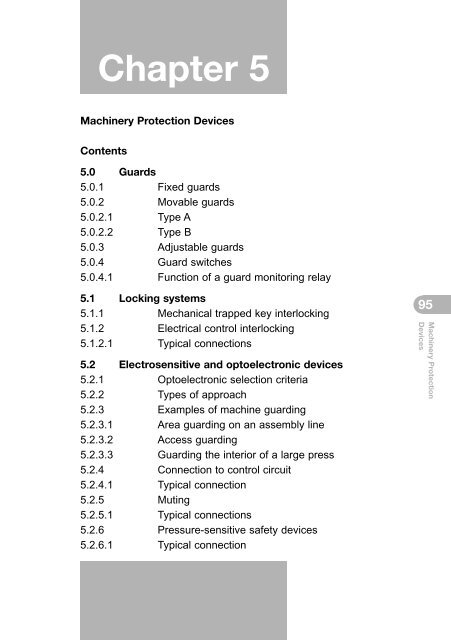
Chapter 5<strong>Machinery</strong> <strong>Protection</strong> <strong>Devices</strong>Contents5.0 Guards5.0.1 Fixed guards5.0.2 Movable guards5.0.2.1 Type A5.0.2.2 Type B5.0.3 Adjustable guards5.0.4 Guard switches5.0.4.1 Function of a guard monitoring relay5.1 Locking systems5.1.1 Mechanical trapped key interlocking5.1.2 Electrical control interlocking5.1.2.1 Typical connections5.2 Electrosensitive and optoelectronic devices5.2.1 Optoelectronic selection criteria5.2.2 Types of approach5.2.3 Examples of machine guarding5.2.3.1 Area guarding on an assembly line5.2.3.2 Access guarding5.2.3.3 Guarding the interior of a large press5.2.4 Connection to control circuit5.2.4.1 Typical connection5.2.5 Muting5.2.5.1 Typical connections5.2.6 Pressure-sensitive safety devices5.2.6.1 Typical connection95<strong>Machinery</strong> <strong>Protection</strong><strong>Devices</strong>
5.3 Emergency stop devices5.3.1 Emergency stop switch5.3.2 Emergency stop circuit5.3.3 Final control element in a safety circuit5.3.4 Typical connections5.4 Two-hand controls5.4.1 Typical connection5.4.2 Programmable electronic systems (PES) fortwo-hand control96<strong>Machinery</strong> <strong>Protection</strong><strong>Devices</strong>
5.0 GuardsA guard is defined as part of a machine that is used specifically toprovide protection by means of a physical barrier (EN 292-1, Section3.22). Section 1.4 of the <strong>Machinery</strong> Regulations concerns guardsand protection devices, and states that in general these must:2Be robustNot give rise to any additional riskNot be easy to bypass or render non-operational(fixed enclosing guard)Be located an adequate distance away from thedanger zone (fixed distance guard)Cause minimum obstruction, enabling essentialwork to be carried out without dismantling theguard.A suitable risk assessment must be carried out on the specificmachine to ensure that the appropriate guard is selected anddesigned.5.0.1 Fixed guardsThese guards are fixed in place, i.e. not welded or fastened, and canonly be removed with the aid of tools (i.e. not with a coin or nail file).Where possible, fixed guards should not be able to remain in place ifthe fixings are removed (i.e. it should not be possible to lean theguard in order to cover the danger zone). A fixed guard may be thesimplest of all the protection devices, but there are still someimportant aspects to consider in their application. The best strategyis to refer to the following specifications:97<strong>Machinery</strong> <strong>Protection</strong><strong>Devices</strong>
98<strong>Machinery</strong> <strong>Protection</strong><strong>Devices</strong>EN 953 (Safety of machinery. Guards. Generalrequirements for the design and construction of fixedand movable guards). This is the starting point. Thisspecification will describe such things as guardheight, mechanical requirements and fixings.EN 294 (Safety of machinery. Safety distances toprevent danger zones being reached by the upperlimbs).EN 349 (Safety of machinery. Minimum gaps to avoidcrushing of parts of the human body).EN 811 (Safety of machinery. Safety distances toprevent danger zones being reached by the lower limbs).5.0.2 Movable guards5.0.2.1 Type AWhere possible, these must remain fixed to the machine. Whenthese guards are open they must be combined with a locking deviceto prevent moving parts starting up while the danger zone is beingaccessed. A stop command must be given when the guard is open.5.0.2.2 Type BThese must be designed and incorporated into the control system sothat moving parts cannot start up while they are within the operator’sreach. The exposed person must not be able to reach moving partsonce these are in motion. These guards can only be adjusted withthe aid of a tool or key. If any of the components on the guard fail,the machine will be prevented from starting. If the machine hasalready started up, all moving parts will be stopped. The function ofthe associated locking device may be more or less sophisticated,depending on the type of hazard, frequency of opening, etc.3
4This will be determined by the risk assessment. Guards that meet therequirements of Type B must be regarded carefully. Does theopening of the guard:a) Stop the entire machine by disconnecting the powerb) Stop moving parts in the danger zone, guarded for the duration ofthis opening period?To comply with the requirements of a), the guard switch or switchescan be treated as an emergency stop function. A suitable andsufficient risk assessment can be carried out using the criteriaexplained in Chapter 4. This type of interlocking is called powerinterlocking (EN 1088).To comply with the requirements of b), the method and integrity of theguarding control circuit has to be assessed as an individual item andthe relevant specifications consulted. A risk assessment will alsohave to be performed. This type of interlocking is called controlinterlocking (EN 1088).5.0.3 Adjustable guardsAdjustable guards are used to allow access only to those areaswhere it is strictly necessary. It should be possible to adjust theseguards both manually and automatically, without the use of tools.Where adjustable guards are required, operators should have accessto other protective devices such as jigs or push sticks, for example.5.0.4 Guard switchesThe criteria for guard switches are similar to those of the emergencystop switch, i.e. the switch actuator moves the contacts along withit to achieve separation of the contact element (EN 292-2,EN 60947-5-1).99<strong>Machinery</strong> <strong>Protection</strong><strong>Devices</strong>
Fig. 8: The guard switch100When a single actuator is used to drive the switch it must be of thepositive type, i.e. the actuator is held depressed by the open guard.This is called positive mode actuation.5<strong>Machinery</strong> <strong>Protection</strong><strong>Devices</strong>Guard openGuard closedFig. 9: Positive mode actuation5.0.4.1 Function of a guard monitoring relayThe function of the guard monitoring relay is:a) To monitor itself for functionality and integrityb) To monitor the switches for functionality (opening and closing)c) To monitor the switches for integrity (shorts etc.)d) To monitor the switches for sequence (guard positioning).
PNOZ X6PST 26Fig. 10: Two-channel control forposition monitoringFig. 11: Two-channel control, highintegrity101<strong>Machinery</strong> <strong>Protection</strong><strong>Devices</strong>PNOZXM1Fig. 12: Three-channel switches conforming to EN 422 and EN 201NB. Please refer to Pilz Safety Catalogue (1) for relay details.
5.1 Locking systemsLocking systems can be divided into two basic types: mechanicaltrapped key interlocking and electrical control interlocking. Trappedkey interlocking is a proven high-integrity safety system that complieswith the design principles identified in EN 954-1, EN 1088, EN 292-1and EN 1050. All energy sources (e.g. electrical, pneumatic,hydraulic) can be reduced to zero, providing unrivalled operatorprotection. Such a system is also very easy to retrofit and can becustomised to individual applications. Control interlocking offers rapidaccess, machine diagnostics, ease of maintenance and the ability tomaintain power to the PLC.102<strong>Machinery</strong> <strong>Protection</strong><strong>Devices</strong>5.1.1 Mechanical trapped key interlockingIn many applications, mechanical interlocking provides the onlypracticable method of safeguarding a machine or suite of machines.This system ensures that a prescribed sequence of actions is takenwhen accessing a machine. It is of particular use where there aremultiple hazard types or where access is required to a number ofdanger zones over a wide area. The principle behind mechanical keyexchange control is that all sources of power are isolated and allstored energy dissipated before the hazardous area of the machinecan be accessed. This tried and tested methodology can be used onall machine installation categories.A number of products can be configured to safeguard a diverse rangeof hazards. Interlocks can be used to lock gates and to spool valvesand isolators. They can also be used to ensure that sources ofstored energy are made safe. Locks are designed in such a way thatthe key can only be removed when the hazard has been isolated andcan only be reinstated when the key is trapped in the lock. Thismeans that the key represents the hazard status associated with that
lock. Keys are uniquely coded and can therefore control thesequence and limit access to authorised personnel.Time delay units can be used where a machine has a rundownperiod. Under this system it is not possible to take out the key untilpower has been removed and the pre-set time period has elapsed. Ifthe rundown period is predictable, the machine can be presumed tohave come to rest and the key can be used in the next sequence ofmachine access.EXCHANGEThe key from theelectrical supply istrapped in themechanical exchangebox, allowing theaccess keys to befreed.ISOLATERemoving the keyturns the electricalsupply OFF103<strong>Machinery</strong> <strong>Protection</strong><strong>Devices</strong>LINKKey can transferto / from controlinterlockACCESSThe access keys areinserted into the accesslocks to allow entry. Asecond key can befreed to provideoperator protection.Fig. 13: Typical key exchange system
AmStop4 AmStop4 AmStop4FORTRESINTERLOCKFORTRESINTERLOCKFORTRESINTERLOCK113RR2241 5 3 72 64+V/L0V/N106Reset13 23 2411<strong>Machinery</strong> <strong>Protection</strong><strong>Devices</strong>A1 S33 S34PNOZ X5S11 S12 A214 S12 S22Fig. 15: AMSTOP from Fortress Interlocks connected to a Pilz PNOZ X5, complyingwith category 3, EN 954-1Using the two normally closed outputs on the AMSTOP with areference point from the safety relay, this connection is single-faulttolerant and therefore meets the requirements of category 3,EN 954-1. This is because both outputs from the AMSTOP mustrespond correctly. If a fault occurs in one channel (for example, theoutput not breaking or closing, or a fault to earth), the PNOZ X5 willnot reset. Auto reset is available with this connection.
FORTRESSINTERLOCKSFORTRESSINTERLOCKSAmLokFORTRESSINTERLOCKSFORTRESSINTERLOCKSAmLokFORTRESSINTERLOCKSFORTRESSINTERLOCKSAmLok1133224411RYL222 14 5 7 6 121 13 3 41 2+ -+V/L0V/NK113 23 24UnlockA1 17 25 35 Y1 Y214StartStopA1 S33 S34PNOZ X 2.S21 S22 A214 S11 S12K1PZA18 26 36 16 A2109<strong>Machinery</strong> <strong>Protection</strong><strong>Devices</strong>K1Fig. 18: AMLOK from Fortress Interlocks connected to a Pilz PNOZ X2 and PZA safetytimer, complying with category 4, EN 954-1
FORTRESINTERLOCKFORTRESINTERLOCKAutoLok4FORTRESINTERLOCKFORTRESINTERLOCKAutoLok4FORTRESINTERLOCKFORTRESINTERLOCKAutoLok4L1L2L324VDC11332122124R4Y2 14 5 7 6 121 13 3 41 2+ -+V/L0V/NUnlockK11013 23 24A1 S33S34PNOZ X 2.A1 13 23 41 L1 L2 L3PSWZ15<strong>Machinery</strong> <strong>Protection</strong><strong>Devices</strong>S21S22 A214 S11S12S1 K214 24 42 Y30 Y31Y32 Y1 Y2 A20 V + 24 V outKKMS0KK0VK K K KFig. 19: AMLOK from Fortress Interlocks connected to a Pilz PNOZ X2 and PSWZstandstill monitor, complying with category 4, EN 954-1
16Fig. 18:With the AMLOK normally closed output contacts closed, the PNOZX2 will energise, making its safety outputs 13 and 14. When the startbutton is depressed, K1 will energise, opening its normally closedcontact. The PZA will then de-energise, opening its safety contacts17 and 18. When the stop button is pressed, K1 will energise,allowing the PZA to perform its delay time function. After the pre-settime has elapsed, PZA will energise, closing its safety contacts 17and 18. The optional release switch can now be pressed, allowingthe AMLOK solenoid to release the lock.Fig. 19:In some cases, for example, where the guarded machine has unevenrundown times, it is not efficient to use a delay timer because it has tobe set permanently to the maximum rundown time. The PSWZstandstill monitor uses the regenerated voltage on two separate coilsof the motor and compares this with a pre-defined set point. With theAMLOK normally closed contacts closed, the PNOZ X2 energises,making its safety contacts 13 and 14, allowing a star delta start bydepressing S1. When the PSWZ detects voltage at points L1, L2 andL3, its safety contacts 23 and 24 will open. When the stop relay S0 ispressed, K2 will de-energise and disconnect the motor from thesupply, allowing the PSWZ to monitor the regenerated voltage. Whenthe pre-determined voltage level is reached, safety contacts 23 and24 on the PSWZ will close. This means the optional release switchS3 can be pressed, energising the AMLOK solenoid and releasingthe lock.111<strong>Machinery</strong> <strong>Protection</strong><strong>Devices</strong>
5.2 Electrosensitive and optoelectronic devicesMechanical guarding, whether fixed or movable, may not alwaysprovide the solution for certain types of machinery. If an operatorrequires regular access to a hazardous area, an electrosensitive oroptoelectronic solution may be better. The advantages are higherproductivity, with protection for both the operator and any third party.However, it is important to remember that this method of guardingoffers no protection against flying materials.112<strong>Machinery</strong> <strong>Protection</strong><strong>Devices</strong>5.2.1 Optoelectronic selection criteriaThe main criteria for specifying an optoelectronic guard are asfollows:Define the zone to be guardedThis is based on the machine’s risk assessment, in which accessto the danger zone can be specified.Define the safety function to be performedHere you will need to define exactly what is to be detected withinthe danger zone:- A finger or hand (required when the operator is near to thehazard). In all cases, the resolution of the active optoelectronicprotection device (AOPD) must be less than or equal to 14 mm.- Arm or body (mainly for perimeter guarding)- Presence of an operator (especially where the guardedmachine is not visible from the control point). This is alsosuitable for guarding the approach to danger zones, and wherevehicles are involved.Comply with the category of the safety-related controlPlease refer to Section 4.4.
Calculate the safety distanceThe safety distance for an AOPD can be calculated as describedin prEN 999 (Safety of machinery. Hand/arm speed. Approachspeed of parts of the body for the positioning of safety devices),or as described in any relevant specification for thecorresponding machine (i.e. press). The minimum distancecalculated using prEN 999 must be acceptable from anoperational and ergonomic point of view. The type and locationof the device must also be assessed in order to give completedetection and protection. If the minimum distance calculated isnot acceptable for operational reasons, other options will need tobe considered.prEN 999 provides the following general formula for calculating theminimum distance from the danger zone:S = (K * T) + C,where:SKTCis the minimum distance in mm from the hazardous zone to thedetection pointis the approach speed of the body or parts of the body (in mmper second)is the overall stopping performance in secondsis the additional distance in mm, based on intrusion towards thedanger zone prior to actuation of the protective equipment.113<strong>Machinery</strong> <strong>Protection</strong><strong>Devices</strong>Other factors should also be taken into account, such as theresolution of the AOPD. Annex C of EN 692 (Mechanical presses.Safety) provides the following table with regard to parameter C:
Detection capability Additional distance C Cycle initiation byin mm in mm the AOPD≤ 14 0>14 ≤ 20 80 Permitted> 20 ≤ 30 130> 30 ≤ 40 240 Not permitted> 40 850Fig. 20: Additional distance parameter C from EN 692114<strong>Machinery</strong> <strong>Protection</strong><strong>Devices</strong>5.2.2 Types of approachGenerally we can distinguish between three types of approach:Limit ofprotectedfieldPerpendicularAngularParallel.SHazardouszoneLimit of protected fieldDirection ofpenetrationHazardouszoneLimit of protected fieldSHazardouszone19Direction ofpenetrationAOPDDirection ofpenetrationAOPDHßSAOPDHHFloorFloorFloorFig. 21: Types of approach
The following table shows the formulae for calculating the safety distance S:20Perpendicularapproachß = 90˚ (± 5˚) S = 2000T + 8 * (d – 14) NB. To prevent bypassing thed = ≤ 40 mm where S > 100 mm AOPD, use EN 294. In practice,this standard is not alwaysapplicable because it regardsthe hand as a deformableelement. In this case it isnecessary to seek the adviceof an accident prevention body.where S > 500 mmtake S = 1600T + 8 * (d – 14).In this case S cannot be< 500 mm.40 < d ≤ 70 mm S = 1600T + 850 Height of lowest beam ≤ 300 mmHeight of highest beam ≥ 900 mmd > 70 mm No. of Recommendedmulti-beam S = 1600T + 850 Beams heights4 300, 600, 900, 1200 mm3 300, 700, 1100 mm2 400, 900 mmsingle beam S = 1600T + 1200 1 750 mmParallel S = 1600T + (1200 – 0.4 * H) 15 * (d – 50) ≤ H ≤ 1000 mm.approach where 1200 – 0.4 * H > 850 mm Where H ≥ 300 mm there is arisk of undetected access underß = 0˚ (± 5˚)the beam to be taken into accountfor H where d ≤ H/15 + 50Angular Where ß > 30 ˚C, cf. d ≤ H/15 + 50 applies to theapproach perpendicular approach; lowest beam.Where ß < 30 ˚C, cf. parallel5˚ < ß < 85˚ approach;S then applies to the furthestbeam whose height ≤ 1000 mmS: Minimum distance H: Height d: Resolutionß: Angle between plane of detection and direction of penetration T: TimeFig. 22: Formulae for calculating the safety distance115<strong>Machinery</strong> <strong>Protection</strong><strong>Devices</strong>
5.2.3 Examples of machine guarding5.2.3.1 Area guarding on an assembly lineThe diagrams below show two ways of installing an AOPD for thesame application (access guarding), taking into account both aperpendicular and a parallel approach, as described above. It isassumed that this is the only way in which the machine can beaccessed, that the risk is one of severe injury, and that the operatorhas frequent access to the hazardous zone.320 mmx = d (or refer to C Standard)116<strong>Machinery</strong> <strong>Protection</strong><strong>Devices</strong>Y mmAOPD: resolution 14 mmFig. 23: Perpendicular approach: point of operation guarding combined with area guardingThe calculation shown in the diagram results in a safety distance of320 mm. This safety distance will increase if the resolution is reduced.In any case, the safety distance shall not be less than 100 mm. TwoAOPDs are used to avoid the risk of non-detection: one is vertical andis positioned at the safety distance (perpendicular approach), and theother is horizontal and is intended to prevent non-detection behindthe vertical AOPD.FloorHazardouszoneAStopping time withAOPD = 160 msS = 2000 * 0.16 + 8 (14 - 4)S = 320 mm21According to EN 294 (Safety of machinery. Safety distances to preventdanger zones being reached by the upper limbs), if height “A” of thedanger zone is 1000 mm, y equals 1800.
1256 mm minimumx = d < H / 15 + 50 (or refer to C Standard)Hazardous zoneH = 500 mmAOPD: resolution 30 mmStopping time withAOPD = 160 mswhere H = 500 mmS = 1600 * 0.16 + (1200 - 0.4 * 500)S = 1256 mmC > 850 mmFloorFig. 24: Parallel approach: area guarding22In this case a horizontal AOPD is used. The diagram above showsthe calculation of the safety distance S and the positioning of theAOPD. If the installation height of the AOPD is increased beyond300 mm the safety distance will be less, but you will need to allow forthe risk of a person entering the hazardous zone undetected bypassing under the AOPD. In such a case you would need to installan additional device, based on the risk assessment.Fig. 25 shows the results of both these methods. Operating constraintswill enable you to decide which is best for your application.117<strong>Machinery</strong> <strong>Protection</strong><strong>Devices</strong>AdvantagesDisadvantagesSolution no. 1 Higher productivity because Safety device is moreS = 320 mm the operator is closer. expensive.The short distance between thevertical barrier and the hazardouszone enables material to be storedclose to the machine.Solution no. 2 Safety device is less expensive. Operator much further away.S = 1336 mm Enables access to be guarded, Difficult to store products on theregardless of the height ofground because the barrier takes uphazardous zone “A”.a great deal of space.Lower productivity.Higher productivity cost.Fig. 25: Advantages/disadvantages of perpendicular and parallel approach
5.2.3.2 Access guardingPerimeter guarding using 3 beams (at heights of 300, 700 and1100 mm) allows for a perpendicular approach as described above.This method must allow for the possibility of the operator becomingundetected between the AOPD and the hazardous zone, so additionalprecautions will need to be taken. For example, the local controlshould be positioned in such a way that the whole of the hazardouszone is visible; it should also be beyond the reach of the operatorwhile in the hazardous zone.1181106 mm minimumon all sides with accessto the machine1100Hazardous zone23<strong>Machinery</strong> <strong>Protection</strong><strong>Devices</strong>Fig. 26: Access guarding700300FloorStopping time withAOPD = 160 mswhere H = 300 mmS = 1600 * 0.16 + 850S = 1106 mm5.2.3.3 Guarding the interior of a large pressThis type of guarding is recommended for large presses that can beaccessed at ground level. In such a case it is necessary to stop thepress starting up while the operator is inside. It is important to notethat this is a secondary guarding system that should on no accountreplace the main guarding system (consisting of an AOPD or twohandcontrol). The safety distance must be calculated for the mainguarding system, whose function is to stop the press, and not for thesecondary guarding system, which detects the presence of anoperator inside the press and prevents the press from starting up.
5.2.4 Connection to control circuitEach safety device must be incorporated into the machine’s controlsystem to form an integral part. This means that all parts of thecontrol system - the relevant part of the machine’s control circuit, itsconnection to the safety device and the safety device itself – musttake into account the category defined during the risk assessment (asper EN 954-1 and EN 61496).24The diagrams overleaf explain the safety categories suitable for anAOPD and control unit, in line with EN 954-1, taking into account thewhole system, including the stop valve. The diagrams also show howsafety devices of a particular category react in the event of a fault. Ifa safety device is activated under normal operating conditions (e.g. ahand enters the protected field), the machine will always stop,regardless of the safety category. Fault tolerance in the respectivesafety categories will differ.For further reading on the application of electrosensitive andoptoelectronic devices, please refer to the guidance documentHSG180, available from the HSE.119<strong>Machinery</strong> <strong>Protection</strong><strong>Devices</strong>
Category 2<strong>Protection</strong> fieldfreeoccupiedNormaloperationOperationwith errorSafety function may be lostbetween checks. Faultsdetected at time of externaltest. Risk of accident in theperiod between the faultoccurring and the next test.External test cycleTTTTTOSSD / FSDonoffRISK120<strong>Machinery</strong> <strong>Protection</strong><strong>Devices</strong>Category 3<strong>Protection</strong> fieldExternal test cycleOSSD / FSDCategory 4<strong>Protection</strong> fieldExternal test cycleOSSD / FSDfreeoccupiedT1 onoff2onofffreeoccupied1 onoff2onoffTTTNormaloperationTNormaloperationTTTTTTTOperationwith errorTTOperationwith errorTTTTA single fault assures thesafety function as an outputsignal for stopping can stillbe generated (e.g. if a handenters the protection field).The fault is detected eitherwhen the hand enters theprotection field or by internalchecking.Accumulation of faults maylead to loss of the safetyfunction.The system shall be designedso that a single fault in anyof its parts does not lead tothe loss of safety functions.A single fault still assures thesafety function. In additionto category 3 the safetyfunction must be assured incase of an accumulation offaults. Internal tests musttherefore be within theresponse time of the safetydevice.The single fault is detectedat or before the next demandon the safety function. If thedetection is not possible thenan accumulation of faultsshall not lead to a loss of thesafety function.Fig. 27: Suitable safety categories in line with EN 954-1
5.2.4.1 Typical connection+ 24 VDC1FGS5 6 7 3 4 2K1M25121Reset131424VY32Y350VA1 S52 S12 S22 S21 13 23 33 41 Y36PNOZ 83 1 3 2S11 Y1 Y2 A3 14 24 34 42 Y37 A22K1 K2 K31 3K1K2K3K2MM3<strong>Machinery</strong> <strong>Protection</strong><strong>Devices</strong>K1MK2MFig. 28: Typical connection of a category 4 device (Pilz PNOZ 8) with a Sick FGS lightcurtain, manual reset
5.2.5 MutingThe muting of protective devices raises the problem of aninstallation’s safety. For example, EN 415-4 (Palletizers anddepalletizers) relates to packaging machinery on which all operationson the palletised load are carried out entirely and automatically bymachine. Under normal operating conditions, there is a risk at boththe entrance and exit of the interior zone. The AOPD must be mutedat the moment the pallet passes through, but it must also be possibleto detect the presence of an operator. The muting system musttherefore be able to discriminate between the pallet and the operator.26122<strong>Machinery</strong> <strong>Protection</strong><strong>Devices</strong>The muting conditions defined in standard EN 415-4 state that:Muting may only occur during the operating cycle when theloaded pallet obstructs access to the hazardous zoneMuting shall be automaticMuting shall not depend on a single electrical signalMuting shall not depend entirely on software signalsIf muting signals occur as part of an invalid combination,they shall not allow a state of muting, or they shall ensurethat the machine is locked outThe state of muting must be deactivated as soon as thepallet has passed through the detection zone.The diagrams below show how a light curtain can be used to meet allthese requirements. The device incorporates a system of temporarymuting by automatic discrimination. The AOPD is muted by thesensor pairs A1/A2 and B1/2. In this case the distance between A1and B2 must be less than the length of the pallet. The light curtaincan also be used to define the maximum duration of the mutingperiod, in stages of 1 second.
LCU-P outputin ON stateAOPD outputA1A2B1B2Muting< 50 ms > 50 msFig. 29: Muting: pulse diagramFigs. 30 and 31 give a schematic overview of the muting process.27123A1 A2 B1 B2 LCUFig. 30: Muting: the conveyed material is identified; no muting signal is emitted<strong>Machinery</strong> <strong>Protection</strong><strong>Devices</strong>A1 A2 B1 B2 LCUFig. 31: Muting: the operator is identified; the light curtain initiates an (emergency) stop
3 4B SERIESRECEIVER224VDC13 4B SERIES2EMITTER 24VDCL N E1A1S12S22S33S34A2PILZPNOZ X513142324F1 1A24VDCPOWER SUPPLYeg. LUTZ 722-9300VMUTE 1MUTE 224VF2 2AA1 A2 S33 S34S1113PILZPNOZ X2.114S12S21S222324B1 B2 S11 S12S21 13PILZPNOZ X314S222324S3133S3234SAFETY O/P 1SAFETY O/P 2SAFETY O/P 329125<strong>Machinery</strong> <strong>Protection</strong><strong>Devices</strong>S33 S34NOTES1) MUTE 1 & 2 INPUTS SHOULD BE FORCEDBREAK LIMIT SWITCHES2) IF THE APPLICATION REQUIRES A FAILSAFEMUTE INDICATOR, A UNIT WITH FAILSAFEMONITORING OF THE MUTE DEVICESHOULD BE USEDMONITOREDMAN. RESET.FEEDBACK FROMEXTERNALCONTACTORSFig. 33: Typical muting circuit using Pilz safety relaysNB. Please refer to Pilz Safety Catalogue (1) for relay details.
5.2.6 Pressure-sensitive safety devicesAnother alternative to mechanical guarding is to use a device that willsense presence by contact, i.e. a pressure-sensitive device. The twomost common types are contact-sensing bumpers and pressure mats.These devices are manufactured following the guidance of EN 1760-1(Safety of machinery. Pressure-sensitive protective devices).30126<strong>Machinery</strong> <strong>Protection</strong><strong>Devices</strong>The technology used in these devices may consist of wires or opticalfibres, wire being the most common type at the moment. They areinstalled in accordance with prEN 999 (Safety of machinery.Hand/arm speed. Approach speed of parts of the body for thepositioning of safety devices). Such devices will allow access whererequired, without the constraints of mechanical interlocked guards. Forexample, in robot cells where access is required in order to teach therobot, pressure mats on the floor are interlocked into the safety systemto prevent the operator straying into the hazardous area. Contactsensing bumpers can be used on safe edges on numerous machineapplications or as bumpers on automatic guided vehicles (AGVs).5.2.6.1 Typical connectionResetFinal control elementFig. 34: Typical pressure mat connection with Pilz PNOZ 16NB. Please refer to Pilz Safety Catalogue (1) for relay details.
5.3 Emergency stop devicesEvery machine must be fitted with a control to bring it to a completestop safely. On a complex machine, each workstation must be fittedwith a stop so that all or some of the moving parts can be renderedsafe. Where machinery has complex movements or high inertias, thestop function must not cause damage to the machine or create adangerous situation. This means it is vital to consider the way inwhich the machine is brought to a safe condition. The energy supplyto the machine’s actuators must be removed once the stop has beenachieved.Section 9 of EN 60204-1 categorises stop functions as follows:Category 0: Stopping by immediate removal of power to themachine actuators, all brakes or mechanical devicesbeing activated (i.e. an uncontrolled stop).Category 1: Stopping by means of the machine actuators (i.e. acontrolled stop). Power is finally removed once the stophas been achieved.31127<strong>Machinery</strong> <strong>Protection</strong><strong>Devices</strong>Category 2: A controlled stop with the power left available to themachine actuators.In reality, all machinery should be fitted with a category 0 stopfunction, but where safety or functional requirements demand it,category 1 or 2 should be provided. Category 0 and 1 stops havepriority over all machine functions.
5.3.1 Emergency stop switchThe switch is the device that initiates the emergency stop. It mustsustain this signal until disengaged by the appropriate action.EN 418 is the consultative document for emergency stopping,explaining the differences between the design of a normal stop andan emergency stop. It defines the safety requirements of the deviceas “having the principle of positive actuation to achieve contactseparation that is not dependent on springs …Any action on theactuator which generates the signal for an emergency stop mustresult in a latching of that actuator. The resetting of the actuator shallbe only by a manual action”.32128The emergency stop switch actuator may take different forms,depending on the application in which it is being used, for example:<strong>Machinery</strong> <strong>Protection</strong><strong>Devices</strong>Mushroom-headed buttonsBarsLeversKick-platesPressure-sensitive cables.The colour or the actuator must be red. Where used, the backgroundcolour must be yellow.5.3.2 Emergency stop circuitThe integrity of the circuit can be decided in conjunction with the riskassessment. EN 954-1 outlines the requirements for safety-relatedcontrols. In general, the stop circuit can be viewed along thefollowing lines.
E-StopFinal control elementFig. 35: Category B and 1 stop circuitThis is the type of circuit that meets the requirements of categories Band 1, in accordance with EN 954-1. The emergency stop pushbutton has positive actuation and will always break the circuit. Thecontrol relay is a spring-return device. As the failure mode is notclearly defined, this could lead to failure to closed circuit. However,the aim of these categories is to achieve good design using well-triedcomponents and, if a failure does occur, the risk to the operator orenvironment is low.33129<strong>Machinery</strong> <strong>Protection</strong><strong>Devices</strong>E-StopResetFig. 36: Category 2 stop circuit using a safety relayFinal control element
The next category of EN 954-1 makes greater demands on thecomponents. Not only do they have to be good by design andnature, but the safety function must also be checked and the loss ofthe safety function must be detected by this check.34130This can be achieved by duplicating the critical safety elements. Thenormal method, as shown, is to use redundant relays whoseactuation is checked on start-up and reset. However, although theemergency stop button is positively driven, if a wiring error or shortoccurs across the switch terminals, the safety circuit will be renderedinoperable. The fault will only be noticed when the button isoperated, so these circuits will require an off-line test, the frequencyof which should be decided by the circuit’s demand rate.<strong>Machinery</strong> <strong>Protection</strong><strong>Devices</strong>E-StopResetFinal control elementFig. 37: Category 3 stop circuit using a safety relay
E-StopResetFinal control elementFig. 38: Category 4 stop circuit using a safety relayIn accordance with EN 954-1, the demands of category 3 include allthose of the previous categories, with the additional requirement thata single fault should not lead to the loss of the safety function andthat this fault, wherever practicable, should be detected.As in the case of category 2, where the critical safety device wasconsidered to be the relay, the input devices must now be duplicatedso their movement can be checked. More switches could be addedto the input circuit, minimising the cost, but this would compromisethe spirit of category 3. For example, if multiple gate switches areused and more than one gate is open, a single fault on one switchmight not be detected. Again, an off-line test may be required.The final category of EN 954-1 has the highest demands on thesafety-critical circuit. These are very similar to those of category 3, inthat no single fault will lead to the loss of the safety function, but withthe additional requirement that the fault be detected at or before thenext call on the safety system. If this is impossible, an accumulationof faults shall not lead to the loss of the safety function.35131<strong>Machinery</strong> <strong>Protection</strong><strong>Devices</strong>
Electromechanical and hydraulic circuits work on three faults (formore details please refer to Chapter 6, Programmable SafetySystems).The input device is duplicated, as in category 3. However, to conformto the requirements, both input devices must have separatemonitored supplies. Multiple input devices are discouraged.36132<strong>Machinery</strong> <strong>Protection</strong><strong>Devices</strong>5.3.3 Final control element in a safety circuitThe old <strong>British</strong> standard BS 2771 established the protection criteria incase of failure to a dangerous condition by recommending aredundant proving system. It went on to suggest that this method beused where intermediate relays are used in a safety circuit. Thiseffectively incorporated safety relays into the safety circuit and left thefinal control element (i.e. the contactor) to good design principles.The new specification EN 954-1 states that the combined safetyrelatedPARTS of a control system start at the point at which thesafety-related signals are initiated and end at the output power controlelements. Future specification EN 61508 will require even more careto be taken over the whole safety-related control system and will laydown some stringent criteria, so it is essential to deal with the finalcontrol element as a relevant part of the safety system.Referring to EN 954-1, the requirements for category 2 onwards arelooking for more than just well-tried components. Well-proven finalelements with a low demand rate on the system might be sufficientfor category 2 and 3, but this really depends on a suitable riskassessment and appropriate design methods. Duplication is almostunavoidable if you wish to meet the requirements of category 4.
Y1Y2Y1E-Stop37133ResetR1R2Y2<strong>Machinery</strong> <strong>Protection</strong><strong>Devices</strong>Fig. 39: The normally closed contact of the final control element is monitored by thefeedback loop Y1/Y2
E-StopY1Y2Y138134<strong>Machinery</strong> <strong>Protection</strong><strong>Devices</strong>ResetY2R1R2Fig. 40: The normally closed contacts of the final control elements R1 and R2 aremonitored by the feedback loop Y1/Y2
R2E-StopY1Y2Y139135Reset<strong>Machinery</strong> <strong>Protection</strong><strong>Devices</strong>Y2R1Fig. 41: The normally closed contacts of the final control elements R1 and R2 aremonitored by the feedback loop Y1/Y2
5.3.4 Typical connectionsL1L2L340136<strong>Machinery</strong> <strong>Protection</strong><strong>Devices</strong>F0Control CircuitfuseF21ThermalOverloadS1EmergencyStopS2StopF0Control CircuitFusesT1ControlTransformerQ1MainIsolatorFuses F1K1MMain ContactorF2ThermalOverloadRelayS3StartK1MK1MMDirect-on-lineStarterFig. 42: Simplified E-Stop circuit for category B & 1
L1L2L3S1EmergencyStopF0Control CircuitfuseF21ThermalOverloadS2StopS3StartF0Control CircuitFusesT1ControlTransformerK1MQ1MainIsolatorFuses F1K1MMain ContactorF2ThermalOverloadRelay41137<strong>Machinery</strong> <strong>Protection</strong><strong>Devices</strong>K1MA1Y113S4ResetY2A2PNOZ X714MK1MDirect-on-lineStarterFig. 43: Simplified E-Stop circuit for category 2 (Pilz PNOZ X7)
L1L2L3F0Control CircuitFusesT1ControlTransformerQ1MainIsolator42138<strong>Machinery</strong> <strong>Protection</strong><strong>Devices</strong>K2MK1MResetF0Control CircuitfuseS1EmergencyStopF2ThermalOverloadS2StopS3StartK1MA1 T11T33T12 T22 13 33PNOZ 1K2MFuses F1K1MContactorK2MContactorF2ThermalOverloadRelayT34A214 34K1MK2MMDirect-on-lineStarterFig. 44: Simplified E-Stop circuit for category 3 (Pilz PNOZ 1)
L1L2L3F0Control CircuitFusesT1ControlTransformerQ1MainIsolatorK2MK1MResetF0Control CircuitfuseS1EmergencyStopF2ThermalOverloadS2StopS3StartK1MA1 S21 S22 S31 S32 1333S33PNOZ X3K2MFuses F1K1MContactorK2MContactorF2ThermalOverloadRelay43139<strong>Machinery</strong> <strong>Protection</strong><strong>Devices</strong>S34A21434K1MK2MMDirect-on-lineStarterFig. 45: Simplified E-Stop circuit for category 4 (Pilz PNOZ X3)
E-StopPP24VMonitored dump valvesV1 V213 3 214414024V0V21 2 323<strong>Machinery</strong> <strong>Protection</strong><strong>Devices</strong>Pilz relayStart0VV1V2 V3 V3Fig. 46: Pilz E-Stop relay used with Norgren monitored dump valves
5.4 Two-hand controlsTwo-hand controls are mainly used to ensure that operators keeptheir hands clear of the danger zone before any movement isinitiated. Applications vary from hedge trimmers to manually-operatedpresses; machine setters can also use two-hand controls when othersafeguards have been locked out. As these controls are only of valueto one specific operator, other safeguards should be considered whenusing more dangerous classes of machinery, either to prevent othersfrom entering the danger zone or to increase the level of protectionfor that operator.All types of two-hand controls must comply with the requirements ofEN 292-1 and, in the case of two-hand control relays, EN 60204. Thedesign and selection will depend upon:The hazard presentThe risk assessmentThe experience of the technology usedOther factors, such as the prevention of accidentalactuation and wilful defeat.45141<strong>Machinery</strong> <strong>Protection</strong><strong>Devices</strong>
EN 574 (Safety of machinery. Two-hand controls) defines 3 types oftwo-hand controls, setting out the minimum measures of safety foreach device, as shown in the table below:46142<strong>Machinery</strong> <strong>Protection</strong><strong>Devices</strong>RequirementsTypesI II IIIA B CUse of both hands (simultaneous actuation) X X X X XRelationship between input signals and output signal X X X X XCessation of the output signal X X X X XPrevention of accidental operation X X X X XPrevention of defeat X X X X XRe-initiation of the output signal X X X XSynchronous actuation X X XUse of category 1 (EN 954-1: 1996) X XUse of category 3 (EN 954-1: 1996) X XUse of category 4 (EN 954-1: 1996)XFig. 47: Minimum safety measures for two-hand devicesThe requirements are listed as follows:Operators shall use both hands during the same time period;this is simultaneous action and is independent of any timelag between the two input signalsThe two activating signals shall initiate and maintain theoutput as long as both signals are presentThe release of one or both activating signals will stop theoutputThe risk of accidental operation shall be minimisedPrevention of accidental operation or prevention of defeatshall be mainly achieved via mechanics and ergonomics
It shall only be possible to reinitiate the output signal afterboth inputs have been releasedThe output signal may only appear when both inputs areactivated within 0.5 seconds of each other. If the inputs arenot actuated synchronously, the output will be preventeduntil the inputs are re-applied within this time scale. This iscalled synchronous actuation.In the case of failure, the parts of the two-hand control device shallbehave in accordance with EN 954-1.5.4.1 Typical connectionInputsPLCOutput supplyInput supplyOutputs47143<strong>Machinery</strong> <strong>Protection</strong><strong>Devices</strong>Y1Y2P2HZ X1EnablemachinemovementFig. 48: Typical two-hand circuit with Pilz P2HZ X1NB. Please refer to Pilz Safety Catalogue (1) for relay details.
5.4.2 Programmable electronic systems (PES) for two-handcontrolThere is still a considerable amount of development to be done intothe ways in which programmable electronic systems can be validatedfor use in safety systems. However, where such systems are beingused to achieve the functional characteristics of a two-hand control,the hardware and software shall be validated in accordance with therisk assessment and the PES guidelines from the HSE (please referto Chapter 6, Programmable Safety Systems).48144It is clear, however, that EN 574 requires that the output signal forTypes IIIB and IIIC two-hand controls should not be generated solelyby a single-channel programmable electronic system.<strong>Machinery</strong> <strong>Protection</strong><strong>Devices</strong>