PRODUCT GUIDE MODEL 463247412 - Char-Broil Grills
PRODUCT GUIDE MODEL 463247412 - Char-Broil Grills
PRODUCT GUIDE MODEL 463247412 - Char-Broil Grills

Create successful ePaper yourself
Turn your PDF publications into a flip-book with our unique Google optimized e-Paper software.
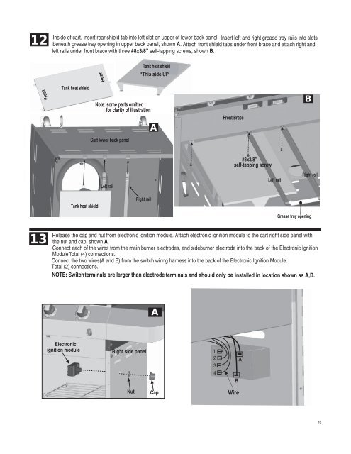
12Inside of cart, insert rear shield tab into left slot on upper of lower back panel. Insert left and right grease tray rails into slotsbeneath grease tray opening in upper back panel, shown A. Attach front shield tabs under front brace and attach right andleft rails under front brace with three #8x3/8” self-tapping screws, shown B.Tank heat shield*This side UPRearFrontTank heat shieldNote: some parts omittedfor clarity of illustrationAFront BraceBCart lower back panel#8x3/8”self-tapping screwLeft railLeft railRight railTank heat shieldRight railGrease tray opening13Release the cap and nut from electronic ignition module. Attach electronic ignition module to the cart right side panel withthe nut and cap, shown A.Connect each of the wires from the main burner electrodes, and sideburner electrode into the back of the Electronic IgnitionModule.Total (4) connections.Connect the two wires(A and B) from the switch wiring harness into the back of the Electronic Ignition Module.Total (2) connections.NOTE: Switch terminals are larger than electrode terminals and should only be installed in location shown as A,B.AElectronicignition moduleRight side panel12 A34BNutCapWire19