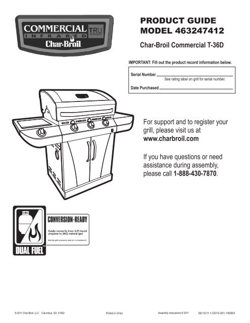
PRODUCT GUIDE MODEL 463247412 - Char-Broil Grills
PRODUCT GUIDE MODEL 463247412 - Char-Broil Grills
PRODUCT GUIDE MODEL 463247412 - Char-Broil Grills

You also want an ePaper? Increase the reach of your titles
YUMPU automatically turns print PDFs into web optimized ePapers that Google loves.
StraightHold coupling nut and regulatoras shown for proper connectionto LP cylinder valve.Leak Testing Valves, Hose and Regulator1.Turn all grill control knobs to OFF.2.Be sure regulator is tightly connected to LP cylinder.3.Completely open LP cylinder valve by turning hand wheelcounterclockwise. If you hear a rushing sound, turn gas offimmediately. There is a major leak at the connection. Correctbefore proceeding.4.Brush soapy solution onto areas circled below, or other similarfittings on your grill.6.Turn the coupling nut clockwise and tighten to a full stop. Theregulator will seal on the back-check feature in the LP cylindervalve, resulting in some resistance. An additional one-half tothree-quarters turn is required to complete theconnection. Tighten by hand only – do not use tools.NOTE:If you cannot complete the connection, disconnect regulator andrepeat steps 5 and 6. If you are still unable to complete theconnection, do not use this regulator!DANGER• Do not insert any tool or foreign object into the valveoutlet or safety relief valve. You may damage the valveand cause a leak. Leaking propane may result inexplosion, fire, severe personal injury, or death.WARNINGNOTE: Sideburnershelf fascia notshown for clarity.NOTE: Your grillmay NOT beequipped with asideburner.• Outdoor gas appliance is not intended to be installedin or on a boat.• Outdoor gas appliance is not intended to be installedin or on an RV.• Never attempt to attach this grill to the self-containedLP gas system of a camper trailer or motor home.• Do not use grill until leak-tested.• If a leak is detected at any time, STOP and call the firedepartment.• If you cannot stop a gas leak, immediately closeLP cylinder valve and call LP gas supplier or your firedepartment!5.If “growing” bubbles appear, there is a leak. Close LPcylinder valve immediately and retighten connections. If leakscannot be stopped do not try to repair. Call for replacementparts.6.Always close LP cylinder valve after performing leak test byturning hand wheel clockwise.6
Ignitor Lighting (continued)8. For grills equipped with ELECTRONIC IGNITION ateach burner:Repeat steps 4 through 6 to light each burner.9. Once each burner has ignited, turn knobs to desired setting.WARNINGTurn controls and gas source or tank OFF when notin use.CAUTIONIf ignition does NOT occur in 5 seconds, turn theburner controls OFF, wait 5 minutes and repeat thelighting procedure. If the burner does not ignite withthe valve open, gas will continue to flow out of theburner and could accidently ignite with risk of injury.Match-LightingsDo not lean over grill while lighting.1. Open lid. Turn ON gas at LP cylinder.2. Place match into match holder (hanging from side panel ofgrill). Light match; then light burner by placing match throughthe match light hole on right or left side of grill.3. Push in and turn far right or far left burner knob to the HIposition, depending on match light hole selected. Be sureburner lights and stays lit.4. Light adjacent burners in sequence by pushing knobs in andturning to the HI position.NOTE: Your grill may NOT be equipped with a Sideburner!Sideburner Ignitor LightingsDo not lean over grill while lighting.1. Open sideburner lid. Turn ON gas at LP cylinder.2. Turn sideburner knob to the HI position, push and holdELECTRONIC IGNITOR button.3. If sideburner does NOT light within 5 seconds, turn knob to OFF,wait 5 minutes, thenrepeat lighting procedure.Sideburner Match Lighting1. Open sideburner lid. Turn ONgas at LP cylinder.2. Place lit match near burner.3. Turn sideburner knob to theHI position.Be sure burner lights andstays lit.8Burner Flame Check• Remove cooking grates and flame tamers. Light burners, rotateknobs from HI to LOW. You should see a smaller flame inLOW position than seen on HI. Perform burner flame checkon sideburner, also. Always check flame prior to each use. Ifonly low flame is seen refer to "Sudden drop or low flame" inthe Troubleshooting Section.HILOWTurning Grill Off• Turn all knobs to the OFFposition. Turn LP cylinder OFF by turninghand-wheel clockwise to a full stop.Ignitor Check• Turn gas off at LP cylinder. Press and hold electronic ignitorbutton. "Click" should be heard and spark seen each timebetween each collector box or burner and electrode. See"Troubleshooting" if no click or spark.Valve Check• Important: Make sure gas is off at LP cylinder beforechecking valves. Knobs lock in OFF position. To checkvalves, first push in knobs and release, knobs should springback. If knobs do not spring back, replace valve assemblybefore using grill. Turn knobs to LOW position then turn back toOFF position. Valves should turn smoothly.Hose Check• Before each use, check to see if hoses are cut or worn or kinked.Replace damaged hoses before using grill. Use onlyvalve/hose/regulator specified by manufacturer.General Grill Cleaning• Do not mistake brown or black accumulation of grease andsmoke for paint. Interiors of gas grills are not painted at thefactory (and should never be painted). Apply a strong solutionof detergent and water or use a grill cleaner with scrub brushon insides of grill lid and bottom. Rinse and allow to completelyair dry. Do not apply a caustic grill/oven cleaner to paintedsurfaces.• Plastic parts: Wash with warm soapy water and wipe dry.sDo not use citrisol, abrasive cleaners, degreasers or aconcentrated grill cleaner on plastic parts. Damage to andfailure of parts can result.• Porcelain surfaces: Because of glass-like composition, mostresidue can be wiped away with baking soda/water solution orspecially formulated cleaner. Use nonabrasive scouring powderfor stubborn stains.• Painted surfaces: Wash with mild detergent or nonabrasivecleaner and warm soapy water. Wipe dry with a softnonabrasive cloth.• Stainless steel surfaces: To maintain your grill’s high qualityappearance, wash with mild detergent and warm soapy waterand wipe dry with a soft cloth after each use. Baked-on greasedeposits may require the use of an abrasive plastic cleaningpad. Use only in direction of brushed finish to avoid damage.Do not use abrasive pad on areas with graphics.• Cooking surfaces: If a bristle brush is used to clean any ofthe grill cooking surfaces, ensure no loose bristles remain oncooking surfaces prior to grilling. It is not recommended toclean cooking surfaces while grill is hot.
CAUTIONSPIDER ALERT!SPIDER AND WEBSINSIDE BURNER TUBE3. Remove carryover tubes and burners.4. Detach electrode from burner.NOTE: Removal/Detachment method will depend on theburner configuration. See different configurations inillustrations below.5. Carefully lift each burner up and away from valve openings.We suggest three ways to clean the burner tubes. Use the oneeasiest for you.(A) Bend a stiff wire (a light weight coat hanger works well)into a small hook. Run the hook through each burnertube several times.If you notice that your grill is getting hard to light or that theflame isn’t as strong as it should be, take the time to check andclean the venturi’s.CONTROL PANELVALVESPIDER WEBSINSIDE VENTURIBURNERIn some areas of the country, spiders or small insects have beenknown to create “flashback” problems. The spiders spin webs, buildnests and lay eggs in the grill’s venturi tube(s) obstructing the flow ofgas to the burner. The backed-up gas can ignite in the venturi behindthe control panel. This is known as a flashback and it can damageyour grill and even cause injury.(B) Use a narrow bottle brush with a flexible handle (do notuse a brass wire brush), run the brush through eachburner tube several times.(C) Wear eye protection: Use an air hose to force air intothe burner tube and out the burner ports. Check eachport to make sure air comes out each hole.6. Wire brush entire outer surface of burner to remove foodresidue and dirt.7. Clean any blocked ports with a stiff wire such as an openpaper clip.8. Check burner for damage, due to normal wear and corrosionsome holes may become enlarged. If any large cracks orholes are found replace burner.VERY IMPORTANT: Burner tubes must reengage valveopenings. See illustrations at right.9. Attach electrode to burner.10. Carefully replace burners.11. Attach burners to brackets on firebox.12. Reposition carryover tubes and attachto burners. Replace flame tamers andcooking grates.Correctburner-to-valveengagementTo prevent flashbacks and ensure good performance the burner andventuri assembly should be removed from the grill and cleanedbefore use whenever the grill has been idle for an extended period.FireboxRemove screwsStoring Your Grill• Clean cooking grates.• Store in dry location.• When LP cylinder is connected to grill, store outdoors in a wellventilatedspace and out of reach of children.• Cover grill if stored outdoors. Choose from a variety of grillcovers offered by manufacturers.• Store grill indoors ONLY if LP cylinder is turned off anddisconnected, removed from grill and stored outdoors.• When removing grill from storage, follow “Cleaning the BurnerAssembly” instructions before starting grill.Cleaning the Burner AssemblyFollow these instructions to clean and/or replace parts of burnerassembly or if you have trouble igniting grill.1. Turn gas OFF at control knobs and LP cylinder.2. Remove cooking grates and flame tamers.FireboxCarryover tubeCarryover tubeFirebox burnerbracketFireboxburnerbracketElectrodeElectrodePry offelectrode witha flat bladescrewdriver9
LIMITED WARRANTYThis warranty only applies to units purchased from an authorized retailer. Manufacturer warrants to the original consumer-purchaser only that thisproduct shall be free from defects in workmanship and materials after correct assembly and under normal and reasonable home use for the periodsindicated below beginning on the date of purchase*. The manufacturer reserves the right to require that defective parts be returned, postage and orfreight pre-paid by the consumer for review and examination.SCOPE OF COVERAGE PERIOD OF COVERAGE TYPE OF FAILURE COVERAGEStainless BurnerFirebox and LidAll Other PartsLimited Lifetime2 years from date of purchase*1 year from date of purchase**Note: A dated sales reciept WILL be required for warranty service.PERFORATION, MANUFACTURING,AND MATERIAL DEFECTS ONLYThe original consumer-purchaser will be responsible for all shipping charges for parts replaced under the terms of this limited warranty.This limited warranty is applicable in the United States and Canada only, is only available to the original owner of the product and is not transferable.Manufacturer requires proof of your date of purchase. Therefore, you should retain your sales slip or invoice. Registering your product is not asubstitute for proof of purchase and the manufacturer is not responsible for or required to retain proof of purchase records.This limited warranty applies to the functionality of the product ONLY and does not cover cosmetic issues such as scratches, dents, corrosions ordiscoloring by heat, abrasive and chemical cleaners or any tools used in the assembly or installation of the appliance, surface rust, or thediscoloration of stainless steel surfaces. RUST is not considered a manufacturing or materials defect.This limited warranty will not reimburse you for the cost of any inconvenience, food, personal injury or property damage.ITEMS MANUFACTURER WILL NOT PAY FOR:1. Shipping cost, standard or expedited, for warranty and replacement parts2. Service calls to your home.3. Repairs when your product is used for other than normal, single-family household or residential use.4. Damage, failures, or operating difficulties resulting from accident, alteration, careless handling, misuse, abuse, fire, flood,acts of God, improper installation or maintenance, installation not in accordance with electrical or plumbing codes, or useof products not approved by the manufacturer.5. Any food loss due to product failures or operating difficulties.6. Replacement parts or repair labor costs for units operated outside the United States or Canada.7. Pickup and delivery of your product.8. Repairs to parts or systems resulting from unauthorized modifications made to the product.9. The removal and/or reinstallation of your product.DISCLAIMER OF IMPLIED WARRANTIES and LIMITATION OF REMEDIESRepair or replacement of defective parts is your exclusive remedy under the terms of this limited warranty. In the event of parts availability issues,the manufacturer reserves the right to substitute like or similar parts that are equally functional.Manufacturer will not be responsible for any consequential or incidental damages arising from the breach of either this limited warranty or anyapplicable implied warranty, or for failure or damage resulting from acts of God, improper care and maintenance, grease fire, accident, alteration,replacement of parts by anyone other than Manufacturer, misuse, transportation, commercial use, abuse, hostile environments (inclement weather,acts of nature, animal tampering), improper installation or installation not in accordance with local codes or printed manufacturer instructions.THIS LIMITED WARRANTY IS THE SOLE EXPRESS WARRANTY GIVEN BY THE MANUFACTURER. NO <strong>PRODUCT</strong> PERFORMANCESPECIFICATION OR DESCRIPTION WHEREVER APPEARING IS WARRANTED BY MANUFACTURER EXCEPT TO THE EXTENT SETFORTH IN THIS LIMITED WARRANTY. ANY IMPLIED WARRANTY PROTECTION ARISING UNDER THE LAWS OF ANY STATE,INCLUDING IMPLIED WARRANTY OF MERCHANTABILITY OR FITNESS FOR A PARTICULAR PURPOSE OR USE, IS HEREBYLIMITED IN DURATION TO THE DURATION OF THIS LIMITED WARRANTY.Neither dealers nor the retail establishment selling this product has any authority to make any additional warranties or to promise remediesin addition to or inconsistent with those stated above. Manufacturer's maximum liability, in any event, shall not exceed the purchase price of theproduct paid by the original consumer.NOTE: Some states do not allow an exclusion or limitation of incidental or consequential damages, so some of the above limitations or exclusionsmay not apply to you. This limited warranty gives you specific legal rights as set foth herein. You may also have other rights which vary from stateto state. In the state of California only, if refinishing or replacement of the product is not commercially practicable, the retailer selling this product orthe Manufacturer will refund the purchase price paid for the product, less the amount directly attributable to use by the original consumer-purchaserprior to discovery of the nonconformity. In addition, in the state of California only, you may take the product to the retail establishment selling thisproduct in order to obtain performance under this limited warranty.If you wish to obtain performance of any obligation under this limited warranty, you shouldwrite to:Consumer RelationsP. O. Box 1240Columbus, GA 31902-1240Consumer returns will not be accepted unless a valid Return Authorization is first acquired. Authorized returns are clearly marked on the outside ofthe package with an RA number and the package is shipped freight/postage pre-paid. Consumer returns that do not meet these standards will berefused.10
PARTS LISTKey Qty DescriptionA 1 BOTTOM SHELFB 1 TANK SCREW, F/ BOTTOM SHELFC 2 CASTER, LOCKINGD 2 CASTER, FIXEDE 1 CART LEFT SIDE PANELF 1 GROMMET, F/ REGULATOR HOLEG 1 CART RIGHT SIDE PANELH 1 CART LOWER BACK PANELI 1 FRONT DOOR BRACEJ 1 HEAT SHIELD, F/ TANKK 1 LEFT RAIL, F/ GREASE TRAYL 1 RIGHT RAIL, F/ GREASE TRAYM 1 FIREBOXN 1 MATCH HOLDERO 3 MAIN BURNER, F/ FIREBOXP 1ELECTRODE, F/ MAIN BURNER,900MM WIREQ 2FLAME CARRYOVER TUBE W/COTTER PINR 1 IGNITER SWITCH MODULES 1HOSE VALVE REGULATORASSEMBLYT 1 MAIN CONTROL PANELU 1 ELECTRONIC IGNITION MODULEV 1 CAP, F/ ELECTRONIC MODULEW 1 ELECTRODE WIRE, F/ SIDEBURNERX 4 BEZEL, F/ CONTROL KNOBY 4 CONTROL KNOBZ 3TEMPERATURE GAUGE, UFCMOUNTEDAA 1 UPPER BACK PANEL, F/ CARTBB 1 LEFT SIDE SHELF, F/ SIDEBURNERCC 1 FASCIA, F/ LEFT SIDE SHELFDD 1 DRIP PAN, F/ SIDEBURNEREE 2RUBBER BUMPER, SIDEBURNER(REAR)FF 1 LID, F/ SIDEBURNERGG 1 SIDEBURNERHH 1 ELECTRODE, F/ SIDEBURNERII 1 RIGHT SIDE SHELFJJ 1 FASCIA, F/ RIGHT SIDE SHELFKK 1 TOP LIDLL 1 HANDLE F/ TOP LIDMM 2 BEZEL, F/ LID HANDLENN 2RUBBER BUMPER, RECTANGULAR,F/ TOP LIDKey Qty DescriptionOO 4 RUBBER BUMPER, ROUND, F/ LIDPP 1 LOGO PLATEQQ 1 HARDWARE F/ TOP LIDRR 1 LEFT DOOR, NO HANDLESS 2 DOOR HANDLETT 1 RIGHT DOOR, NO HANDLEUU 3 FLAME TAMERVV 3 COOKING GRATEWW 1 GRATE, F/ SIDEBURNERXX 1 WARMING RACKYY 1 GREASE TRAYZZ 3 COOKING GRATE, TRAYAAA 2ELECTRODE, F/ MAIN BURNER,600MM WIRENOT PicturedKey Qty Description… 2 DOOR MAGNET… 1 CASTER PIN… 1 HARDWARE PACK… 1 ASSEMBLY MANUAL, ENGLISH… 1 ASSEMBLY MANUAL, SPANISH… 1 CLEANING TOOLNOTE: Some grill parts shown in the assembly steps may differ slightly in appearance fromthose on your particular grill model. However, the method of assembly remains the same.11
PARTS DIAGRAMQQ12BBSRRSSSSTTGGDDWWEEHHIIJJOOPPFFUUVVVVXXVVUUUUOONNLLMMMMKKCCZAAYYZZX X XXYWOAAAAAAPOOQQNABCEFHVIKLMJRDDGCUYYYTZZ
ASSEMBLY1Locking casterPlace bottom shelf upside down. Insert Bent U Pin into the caster mounting plate to lock it in place, shown A.Spin the caster clockwise into the threads on the bottom shelf until secure. Remove the Bent U Pin and repeat for remainingcasters. Make sure the two locking casters are secured at the rear and the non-locking casters are secured at the front.After all 4 casters are secure remove the Bent U Pin and save for future maintenance.Non-lock casterABent U pinFrontBottom shelfRearAttach side panels to bottom shelf using three2 1/4-20x1/2” screws, 7mm lock washers, and1/4-20x1/2” screw7mm flat washers per panel.IMPORTANT: Panel with large hole must7mm lock washerbe on left side of bottom shelf.7mm flat washerLeft side panel(with large hole)Make sure side panelsare pushed as far to therear of bottom shelf aspossible before fullytightening screws.Right side panel13
3Place lower back panel between sidepanels at rear of bottom shelf. Securelower back panel to side panels using two1/4-20x1/2” screws, 7mm lock washers,and 7mm flat washers on each side.Lower back panel1/4-20x1/2” screw7mm lock washer7mm flat washer4This step requires two peopleto lift and position grill headonto cart. Carefully lower the grillhead onto the cart, aligning slots atbottom of grill head with posts oncart side panels. Make sure theregulator hose is hanging outsidethe cart. Grill head must face openside of cart.Grill headRegulator hose14
5On back of grill, place upper back panel between side panels andabove lower back panel. Secure upper back panel, in lower holes,using one 1/4-20x1½” screw, 7mm lock washer, and 7mm flatwasher on each side. Do not fully tighten screws until side shelfinstallation is complete in later steps.1/4-20x1½”screw7mm lockwasher7mm flatwasherUpper back panel6Insert flange on right side shelf into side shelf brackets on side of firebox.Attach right side shelf using three 1/4”-20x3/4” screws, 7mm lock washers, 7mm flat washers, 1/4” nuts, shown A.Attach rear of shelf using one 1/4-20x1½” screw, 7mm lock washer, and 7mm flat washer in lower hole, shown B.Attach front of shelf and fascia using one #8x3/8” self-tapping screw and large flat washer, shown C.Attach front of shelf and fascia using one 1/4”-20x3/4” screw, 7mm lock washer, 7mm flat washer and 1/4” nut, shown D/C.BAFlange into bracket7mm flatwasher1/4-20x1½”screw7mm lockwasher1/4”nut7mm flatwasher7mm lockwasher1/4-20x3/4”screwBracketCD Back of main control panelMain controlpanelFascia, right side shelfLarge flatwasher#8x3/8” self-tappingscrewIgniter Switch1/4-20x3/4”screw1/4”nut7mm lockwasher7mm flat washer15
7Insert flange on left sideburner shelf into side shelf brackets on side of firebox.Attach left sideburner shelf using three 1/4-20x3/4” screws, 7mm lock washers, 7mm flat washers, 1/4” nuts, shown A.Attach rear of shelf using one 1/4-20x1½” screw, 7mm lock washer, and 7mm flat washer in lower hole, shown B.Attach front of shelf and fascia using one #8x3/8” self-tapping screw and large flat washer, shown C.Under main control panel, attach front of shelf and fascia using one 1/4-20x3/4” screw, 7mm lock washer, 7mm flatwasher and 1/4” nut, shown D/E.Now you may fully tighten lower screws on upper back panel.B1/4-20x1½”screw7mm lockwasher7mm flatwasherFlangeintoBracketsALeft sideburner shelfBracket1/4-20x3/4”screwFascia, left sideburner shelf7mm flat 1/4”nutwasher 7mm lockwasherClarge flatwasher#8x3/8” self-tappingscrew1/4”nutEBack of main control panelD7mm flatwasherControl panel7mm lockwasher1/4-20x3/4”screw16
8First, remove the two screws and lock washers factory attached to the sideburner valve bracket. Position sideburnervalve bracket beneath sideburner shelf fascia so that valve stem comes through larger center hole in fascia. Align the holeson valve bracket with left and right holes on fascia. Secure using lock washers and screws that were removed from bracket.Next, place sideburner bezel over valve stem on front side of fascia. Align small holes on bezel with upper and lower holes onfascia. Attach using two #8-32x3/8” screws and 4mm lock washers. Press sideburner control knob onto valve stem.Note: Use left and rightholes on fascia toattach valve bracketScrews and Washersremoved from valve bracketInstall bezel with “OFF” at top.Note: Use upper and lowerholes on fascia toattach bezelControl knob#8-32x3/8” screw4mmlock washerSideburnerfasciaControl knob bezelSideburnervalve bracketValve stem9Insert sideburner burner into left shelf. The stud on bottom of burner fits into rear small hole in sideburner drip pan onshelf, shown A. Secure burner to sideburner drip pan with one Wing nut, shown B. Make sure burner tubeengages sideburner valve, shown C.BSideburner drip panSideburner burnerAWing nutCSideburner drip panBurner tubeValve17
10Under sideburner shelf, attach sideburner ignitor wire to electrode, shown A. Place sideburner grate onto sideburner shelf,aligning grate legs with holes in shelf, shown B.AElectrodeBSideburner grateSideburner Ignitor Wire11Insert front brace under control panel and between cart side panels. Make sure door hinge pins are on the top side andfacing the front. Secure using two 1/4-20x1½” screws, 7mm lock washers, and 7mm flat washers on each side.NOTE: MAKE SURE THAT THE FRONT BRACE IS MOUNTED IN THE MOST DOWNWARD POSITION WHENASSEMBLED TO CART.DoorHinge PinFront brace7mm flatwasher7mm lockwasher1/4-20x1½”screw18
12Inside of cart, insert rear shield tab into left slot on upper of lower back panel. Insert left and right grease tray rails into slotsbeneath grease tray opening in upper back panel, shown A. Attach front shield tabs under front brace and attach right andleft rails under front brace with three #8x3/8” self-tapping screws, shown B.Tank heat shield*This side UPRearFrontTank heat shieldNote: some parts omittedfor clarity of illustrationAFront BraceBCart lower back panel#8x3/8”self-tapping screwLeft railLeft railRight railTank heat shieldRight railGrease tray opening13Release the cap and nut from electronic ignition module. Attach electronic ignition module to the cart right side panel withthe nut and cap, shown A.Connect each of the wires from the main burner electrodes, and sideburner electrode into the back of the Electronic IgnitionModule.Total (4) connections.Connect the two wires(A and B) from the switch wiring harness into the back of the Electronic Ignition Module.Total (2) connections.NOTE: Switch terminals are larger than electrode terminals and should only be installed in location shown as A,B.AElectronicignition moduleRight side panel12 A34BNutCapWire19
14Insert hinge pin on bottom of doors into hole in bottom shelf. Press upper hinge pin in front brace, align hinge hole on top ofdoor, and release hinge pin into door.PRESSTop ofdoorLeft doorRight doorHinge pinon bottomof door15Install flame tamers by sliding one end of each flame tamer into slots at front of firebox and resting opposite end on pins inback of firebox.Note: Some parts omitted forclarity of illustrationFlame tamersFront of fireboxBack of fireboxPin20
16Place cooking grates onto the firebox as shown. Insert the three wire ends at rear of warming rack into holes in back offirebox. Front wires of warming rack rest on sides of firebox.Note: Some parts omitted forclarity of illustrationAssembledwarming rackWarming rackCooking grate17On back of grill, slide grease tray into opening in upper back panel.CAUTIONFailure to install grease tray willcause hot grease to drip from bottomof grill with risk of fire or propertydamage..Grease tray21
18Unscrew electronic ignition cap on cart right side panel. Insert AA battery into ignitor, negative (—) end first.Replace the cap.AA Battery-+Electronic Ignition Cap19LP CYLINDER IS SOLD SEPARATELY. Fill and leak check the cylinder before attaching to grill and regulator (see Use &Care section). Once cylinder has been filled and leak checked, place cylinder into hole in bottom shelf. Make sure cylindervalve is facing front of grill. Secure cylinder with cylinder screw under bottom shelf. Insert regulator through large hole inleft side panel. See Use & Care section of this manual to perform the “Burner Flame Check” and forimportant safety instructions before using.Cylinder screw at rear of cartCylinder screw–Always keep LP cylinders in upright position duringuse, transport, and storage.CAUTIONCylinder valve must face to front of cart oncetank is attached. Failure to install cylindercorrectly may allow gas hose to be damagedin operation, resulting in the risk of fire.RegulatorLP Cylinder( not included)22.
DANGER: If a gas leak cannot be stopped, or a fire occurs due to gas leakage, call the fire department.EmergenciesGas leaking fromcracked/cut/burnedhose.Gas leaking from LPcylinder.Gas leaking from LPcylinder valve.Gas leaking betweenLP cylinder andregulator connection.Fire coming throughcontrol panel.Grease fire orcontinuous excessiveflames above cookingsurface.Possible Cause• Damaged hose.• Mechanical failure due to rusting ormishandling.• Failure of cylinder valve frommishandling or mechanical failure.• Improper installation, connection nottight, failure of rubber seal.• Fire in burner tube section of burner dueto blockage.• Too much grease buildup in burner area.Prevention/Solution• Turn off gas at LP cylinder or at source on natural gas systems. Ifanything but burned, replace valve/hose/regulator. If burned,discontinue use of product until a plumber has investigated causeand corrections are made.• Replace LP cylinder.• Turn off LP cylinder valve. Return LP cylinder to gas supplier.• Turn off LP cylinder valve. Remove regulator from cylinder andvisually inspect rubber seal for damage. See LP Cylinder Leak Testand Connecting Regulator to the LP Cylinder.• Turn off control knobs and LP cylinder valve. Leave lid open toallow flames to die down. After fire is out and grill is cold, removeburner and inspect for spider nests or rust. See Natural Hazardand Cleaning the Burner Assembly pages.• Turn off control knobs and LP cylinder valve. Leave lid open toallow flames to die down. After cooling, clean food particles andexcess grease from inside firebox area, grease tray, and othersurfaces.TroubleshootingProblemBurner(s) will not lightusing ignitor.(See Electronic IgnitionTroubleshooting also)Continued on nextpage.Possible CauseGAS ISSUES:• Trying to light wrong burner.• Burner not engaged with control valve.• Obstruction in burner.• No gas flow.• Vapor lock at coupling nut to LP cylinder.• Coupling nut and LP cylinder valve notfully connected.ELECTRICAL ISSUES:• Electrode cracked or broken; “sparks atcrack.”• Electrode tip not in proper position.• Wire and/or electrode covered withcooking residue.• Wires are loose or disconnected.• Wires are shorting (sparking) betweenignitor and electrode.• Dead battery.Prevention/Solution• See instructions on control panel and in Use and Care section.• Make sure valves are positioned inside of burner tubes.• Ensure burner tubes are not obstructed with spider webs or othermatter. See cleaning section of Use and Care.• Make sure LP cylinder is not empty. If LP cylinder is not empty,refer to “Sudden drop in gas flow.”• For a grill equipped with the AUTO-CLEAN feature, make surethe AUTO-CLEAN valve is set to “Grill”• Turn off knobs and disconnect coupling nut from LP cylinder.Reconnect and retry.• Turn the coupling nut approximately one-half to three-quartersadditional turn until solid stop. Tighten by hand only - do not usetools.• Replace electrode(s).Main Burners:• Tip of electrode should be pointing toward gas port opening onburner. The distance should be 1/8” to 1/4”. Adjust if necessary.Sideburner:• Tip of electrode should be pointing toward gas port opening onburner. the distance should be 1/8” to 3/16”. Adjust if necessary.• Clean wire and/or electrode with rubbing alcohol and clean swab.• Reconnect wires or replace electrode/wire assembly.• Replace ignitor wire/electrode assembly.• Replace with a new alkaline battery.23
Troubleshooting (continued)ProblemBurner(s) will not lightusing ignitor.(See Electronic IgnitionTroubleshooting also)Burner(s) will notmatch light.Sudden drop in gasflow or low flame.Flames blow out.Flare-up.Persistent grease fire.Possible CauseELECTRONIC IGNITION:• No spark, no ignition noise.• No spark, some ignition noise.• Sparks, but not at electrode or at fullstrength.• See “GAS ISSUES:” on previous page.• Match will not reach.• Improper method of match-lighting.• Out of gas.• Excess flow valve tripped.• Vapor lock at coupling nut/LP cylinderconnection.• High or gusting winds.• Low on LP gas.• Excess flow valve tripped.• Grease buildup.• Excessive fat in meat.• Excessive cooking temperature.• Grease trapped by food buildup aroundburner system.Prevention/Solution• See Section I of Electronic Ignition System.• See Section II of Electronic Ignition System.• See Section III of Electronic Ignition System.• Use long-stem match (fireplace match).• See “Match-Lighting” section of Use and Care.• Check for gas in LP cylinder.• Turn off knobs, wait 30 seconds and light grill. If flames are still low,turn off knobs and LP cylinder valve. Disconnect regulator.Reconnect regulator and leak-test. Turn on LP cylinder valve, wait30 seconds and then light grill.• Turn off knobs and LP cylinder valve. Disconnect coupling nut fromcylinder. Reconnect and retry.• Turn front of grill to face wind or increase flame height.• Refill LP cylinder.• Refer to “Sudden drop in gas flow” above.• Clean burners and inside of grill/firebox.• Trim fat from meat before grilling.• Adjust (lower) temperature accordingly.• Turn knobs to OFF. Turn gas off at LP cylinder. Leave lid in positionand let fire burn out. After grill cools, remove and clean all parts.Flashback...(fire in burner tube(s)).Unable to fill LPcylinder.One burner does notlight from otherburner(s).AUTO-CLEAN(If Equipped)Timer does not work(Green light does notflash)No LED’s will illuminate• Burner and/or burner tubes are blocked.• Some dealers have older fill nozzleswith worn threads.• Grease buildup or food particles inend(s) of carryover tube(s).Possible CauseDead BatteryBatteries installed incorrectly.Knob Position did not start the CleanCycleDead Battery• Turn knobs to OFF. Clean burner and/or burner tubes. See burnercleaning section of Use and Care.• The worn nozzles don’t have enough “bite” to engage the valve. Trya second LP dealer.• Clean carry-over tube(s) with wire brush.Prevention/SolutionReplace batteriesInstall batteries correctly.Push Knob in to start the clean cycle. (Green LED should begin toflash)Replace batteriesRed LED next to batterysymbol is illuminatedLow Battery StrengthPrepare to replace batteries (NOTE: Clean cycle will operate witha weak battery.24
Troubleshooting - Electronic IgnitionProblem (Ignition)Possible CauseCheck ProcedurePrevention/SolutionSECTION INo sparks appear atany electrodes whenElectronic Ignition Buttonis pressed; no noise canbe heard from sparkmodule.• Battery not installedproperly.• Dead battery.• Button assembly notinstalled properly.• Faulty spark module.• Check battery orientation.• Has battery been usedpreviously?• Check to insure threads areproperly engaged. Buttonshould travel up and downwithout binding.• If no sparks are generatedwith new battery and goodwire connections, module isfaulty.• Install battery (make sure that “+” and “–”connectors are oriented correctly, with “+” end upand “–” end down.)• Replace battery with new alkaline battery.• Unscrew button cap assembly and reinstall, makingsure threads are aligned and engaged fully.• Replace spark module assembly.SECTION IINo sparks appear atany electrodes whenElectronic Ignition Buttonis pressed; noise canbe heard from sparkmodule.• Output leadconnections notconnected.• Are output connections onand tight?• Remove and reconnect all output connections atmodule and electrodes.SECTION IIISparks are presentbut not at allelectrodes and/or notat full strength• Output leadconnections notconnected.• Arcing to grill awayfrom burner(s).• Are output connections onand tight?• If possible, observe grill indark location. Operateignition system and look forarcing between output wiresand grill frame.• Remove and reconnect all output connections atmodule and electrodes.• If sparks are observed other than from burner(s),wire insulation may be damaged. Replace wires.• Weak battery.• All sparks present but weakor at slow rate.• Replace battery with a new alkaline battery.• Electrodes are wet.• Has moisture accumulatedon electrode and/or in burnerports?• Use paper towel to remove moisture.• Electrodes cracked orbroken “sparks atcrack”.• Inspect electrodes forcracks.• Replace cracked or broken electrodes.25
26NOTES
Warranty Registration DepartmentP.O. Box 1240Columbus, GA 31902-124027