TUTORIAL ON USING XILINX ISE DESIGN SUITE 10.1: Mixing ...
TUTORIAL ON USING XILINX ISE DESIGN SUITE 10.1: Mixing ...
TUTORIAL ON USING XILINX ISE DESIGN SUITE 10.1: Mixing ...
- No tags were found...

You also want an ePaper? Increase the reach of your titles
YUMPU automatically turns print PDFs into web optimized ePapers that Google loves.
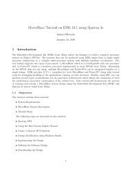
<strong>TUTORIAL</strong> <strong>ON</strong> <strong>USING</strong> <strong>XILINX</strong> <strong>ISE</strong> <strong>DESIGN</strong> <strong>SUITE</strong> <strong>10.1</strong>:<strong>Mixing</strong> VHDL and Schematics “Design of an AdderSubtractor” for Spartan-II E (Digilent D2E Board)Shawki AreibiSeptember 28, 20091 IntroductionThe objective of this tutorial is to show you how VHDL can be incorporated into a schematic designusing the <strong>ISE</strong> tools. At this point, the student should have read and understood the followingdocuments:1. <strong>TUTORIAL</strong> <strong>ON</strong> <strong>USING</strong> <strong>XILINX</strong> <strong>ISE</strong> <strong>DESIGN</strong> <strong>SUITE</strong> <strong>10.1</strong>: Design Entry ofFull Adder Using Schematic Capture2. <strong>TUTORIAL</strong> <strong>ON</strong> <strong>USING</strong> <strong>XILINX</strong> <strong>ISE</strong> <strong>DESIGN</strong> <strong>SUITE</strong> <strong>10.1</strong>: Design Entry UsingVHDL (Full Adder)Students should also be familiar with the Schematic Editor and the Test Bencher in the ProjectNavigator software.The tutorial will first attempt to design a 4-bit adder using VHDL. The next step is to transformthis VHDL code into schematic symbol which will be again used at the schematic capture level todesign an adder/subtractor circuit.2 Starting a new projectSince we wish to combine VHDL with schematic capture, we will create a new project with schematicas the Top-Level Module Type.1. Load the Project Navigator from the → All Programs → Development → Xilinx<strong>ISE</strong> Design Suite <strong>10.1</strong> → <strong>ISE</strong> → Project Navigator.2. The Project Navigator window will appear. Select File → New Project3. The New Project Wizard dialog box will appear. Specify the directory in which you want tostore the project in and give the project a name. In the Top-Level Source Type sectionselect Schematic and click Next.1
4. Another New Project Wizard dialog box will appear prompting you for device, synthesis andsimulation settings for the project.In this dialog box verify the following settings:• Device Family → Spartan2E.• Device → xc2s200e.• Package → pq208.• Speed Grade → -6.• Synthesis Tool → XST (VHDL/Verilog).• Simulator → <strong>ISE</strong> Simulator (VHDL/Verilog).• Generated Simulation Language → VHDL.If the information is correct click Next.5. The next dialog box will ask if you wish to add a new source file to the project. Click NewSource.... A new dialog box will appear prompting you for the file type, name and location.Select VHDL module from the list of file types and name the file ”MyAdder” (ProjectNavigator will append the appropriate file extension). The default location should be theproject directory and ensure the Add to project box is checked.6. In the Define VHDL Source dialog box that appears, add ports A, B and CI as inputs andCO and S as outputs. Click Next when this is done.7. The next dialog box will allow you to confirm the previous choices. Click if they arecorrect.8. You will now return to the New Project dialog box and the ”MyAdder.vhd” source templatethat you have created will now be listed. Click Next. The next dialog box is used to addexisting source files to the project. Since we are only using new source files in this project,click Next. Finally, a confirmation dialog box will appear. Click Finish if the information iscorrect.2
3 Using the HDL Editor for VHDLWe are now ready to start working with the HDL Editor.1. At the completion of the last section the VHDL editor window should now have the templatecode with the variables that you entered. Modify the code to match the following:– 1 bit Full Adderlibrary IEEE;use IEEE.std logic 1164.all;entity fulladd isport (A, B, Ci: in STD LOGIC;Co, S: out STD LOGIC);end fulladd;architecture fulladd arch of fulladd isbeginS ⇐ ((A xor B) xor Ci);Co ⇐ ((A and B) or (Ci and (A xor B)));end fulladd arch;– 4 bit Adderlibrary IEEE;use IEEE.std logic 1164.all;entity adder4 isport (A0,A1,A2,A3: in STD LOGIC;B0,B1,B2,B3: in STD LOGIC;Ci: in STD LOGIC;Co: out STD LOGIC;S0,S1,S2,S3: out STD LOGIC);end adder4;architecture adder4 arch of adder4 isCOMP<strong>ON</strong>ENT fulladdport (A, B, Ci: in STD LOGIC;Co, S: out STD LOGIC);END COMP<strong>ON</strong>ENT;signal tmp: STD LOGIC VECTOR (2 downto 0);3
eginU0: fulladd port map(Ci⇒Ci, A⇒A0,B⇒B0,S⇒S0,Co⇒tmp(0));U1: fulladd port map(Ci⇒tmp(0),A⇒A1,B⇒B1,S⇒S1,Co⇒tmp(1));U2: fulladd port map(Ci⇒tmp(1),A⇒A2,B⇒B2,S⇒S2,Co⇒tmp(2));U3: fulladd port map(Ci⇒tmp(2),A⇒A3,B⇒B3,S⇒S3,Co⇒Co);end adder4 arch;2. We must now check that the syntax of the VHDL code is correct. In the Project Navigatorwindow highlight the VHDL source in the Sources in Project pane. Expandifit is not already and double clickA process will be spawned to verify the VHDLcode for syntax errors.• If there are none, a green check mark will appear next to the Check Syntax process.• If errors where found, A red cross will appear next to the Check Syntax process. Theerrors will be listed in the Errors tab of the Transcript window located at the bottomof the Project Navigator window. In it you will see a listing of the errors and the lineson which they occur. If you double click on an error message a red dot will appear inthe VHDL editor pane next to (or close to) the line where the error was found.3. Once you have eliminated all of the errors, save your work.4. We will now create a module that can be used in the Schematic Editor. Expand theif it is not already and double click. If the process is successful a green checkwill appear next to the process name. Output from the process is shown in the Transcriptwindow at the bottom of the Project Navigator window. We are now ready to use the symbolin a schematic.4 Using the macroNow return to the Project Navigator and add a schematic source to the project.In the Symbols tab of the Options toolbar, the project directory will be listed in the Catagoriespane. Highlight this entry and the adder4 symbol that you have created will be listed in the Symbolspane. You can use it in the same way you use the other components.4
5 Adder/Subtractor CircuitThe addition of two signed binary numbers with negative numbers represented in signed-2’s complementform is obtained from the addition of the two numbers, including their sign bits. A carryout of the sign bit position is discarded.The subtraction of two signed binary numbers when negative numbers are in 2’s complementform is very simple and can be stated as follows: “Take the 2’s complement of the subtrahend(including the sign bit) and add it to the minuend (including the sign bit). A carry out of the signbit position is discarded.5.1 Adder-Subtractor CircuitB3A3B2A2B1A1B0A0FAC3FAC2FAC1FAC0C4SS3 2 1Figure 1: 4-Bit AdderSS0The circuit for subtracting A - B consists of a parallel adder as shown in Figure 1 with invertersplaced between each B terminal and the corresponding full-adder input. The input carry C 0 must beequal to 1. The operation that is performed becomes A plus the 1’s complement of B plus 1. This isequal to A plus the 2’s complement of B. The addition and subtraction operations can be combinedinto one circuit with one common binary adder. This is done by including an exclusive-OR gatewith each full adder. A 4-bit adder-subtractor circuit is shown in Figure 2. Input S controls theoperation.1. When S = 0 the circuit is an adder.2. When S = 1 the circuit becomes a subtractor.Each exclusive-OR gate receives input S and one of the inputs of B, B i . When S = 0, we haveB i ⊕ 0 = B i . If the full adders receive the value of B, and the input carry is 0, the circuit performsA plus B. When S = 1, we have B i ⊕ 1 = ¯B i and C 0 = 1. The circuit performs the operation Aplus the 2’s complement of B.5
B 3 B 2 B1 B 0SA 3A 2A1A0FAC3FAC2FAC1FAC0C4S3 S2 S1S0Figure 2: 4-Bit Adder/Subtractor6 Appendix A - User Constrained File (UCF)A User Constraint File (UCF) is used to assign I/O pins in a design to the actual pins on theFPGA.The UCF file has the following format:NET LOC=P6.1 LEDsThe Digilent DIO1 Board provides a series of eight LEDs (LD1–LD8) and four multiplexed 7-segment displays (DSP1) for use by a Digilent 2E FPGA Board. All of these LEDs are Largeactive high meaning that an LED segment will glow when a logic-high is applied to it. Thefollowing tables show the connection from the Digilent 2E Board to the LEDs on the DIO1 Boardexpressed as UCF constraints.—DescriptionNET SEGANET SEGBNET SEGCNET SEGDNET SEGENET SEGFNET SEGGNET SEGDP—LocationLOC=P127LOC=P132LOC=P134LOC=P136LOC=P139LOC=P141LOC=P146LOC=P148Table 1: Connections between DIO1 7-Segment display and Digilent 2E6
—DescriptionNET LD < 1 >NET LD < 2 >NET LD < 3 >NET LD < 4 >NET LD < 5 >NET LD < 6 >NET LD < 7 >NET LD < 8 >—LocationLOC=P154LOC=P161LOC=P163LOC=P165LOC=P167LOC=P169LOC=P174LOC=P176Table 2: Connections between the DIO1 LEDs and Digilent 2E—DescriptionNET SW < 1 >NET SW < 2 >NET SW < 3 >NET SW < 4 >NET SW < 5 >NET SW < 6 >NET SW < 7 >NET SW < 8 >—LocationLOC=P126LOC=P129LOC=P133LOC=P135LOC=P138LOC=P140LOC=P145LOC=P147Table 3: Connections between the DIO1 slide switches and Digilent 2E6.2 SwitchesThe DIO1 has bank of eight slide switches and five pushbuttons (labeled BTN1 through BTN5)that are accessible from an Digilent 2E Board.When closed or <strong>ON</strong>, each DIP switch pulls the connected pin of the D2E Board to ground.When the DIP switch is open or OFF, the pin is pulled high through a 10KΩ resistor.When pressed, each pushbutton pulls the connected pin of the D2E Board to ground. Otherwise,the pin is pulled high through a 10KΩ resistor. The table below show the connections from theDigilent D2E Board to the switches on the Digilent IO1 Board expressed as UCF constraints.—DescriptionNET BTN < 1 >NET BTN < 2 >NET BTN < 3 >NET BTN < 4 >NET BTN < 5 >—LocationLOC=P149LOC=P150LOC=P151LOC=P152LOC=P178Table 4: Connections between the DIO1 pushbuttons and Digilent 2E7