Tutorial - Using Xilinx System Generator 13.2 for Co-Simulation on ...
Tutorial - Using Xilinx System Generator 13.2 for Co-Simulation on ...
Tutorial - Using Xilinx System Generator 13.2 for Co-Simulation on ...

Create successful ePaper yourself
Turn your PDF publications into a flip-book with our unique Google optimized e-Paper software.
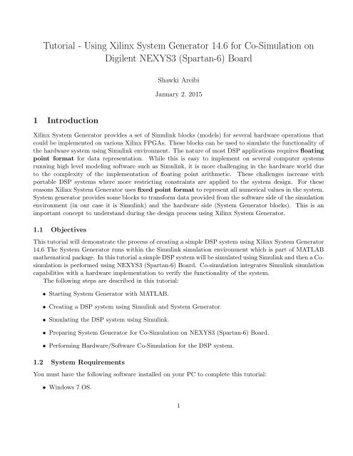
<str<strong>on</strong>g>Tutorial</str<strong>on</strong>g> - <str<strong>on</strong>g>Using</str<strong>on</strong>g> <str<strong>on</strong>g>Xilinx</str<strong>on</strong>g> <str<strong>on</strong>g>System</str<strong>on</strong>g> <str<strong>on</strong>g>Generator</str<strong>on</strong>g> 14.6 <str<strong>on</strong>g>for</str<strong>on</strong>g> <str<strong>on</strong>g>Co</str<strong>on</strong>g>-<str<strong>on</strong>g>Simulati<strong>on</strong></str<strong>on</strong>g> <strong>on</strong>Digilent NEXYS3 (Spartan-6) BoardShawki AreibiJanuary 2, 20151 Introducti<strong>on</strong><str<strong>on</strong>g>Xilinx</str<strong>on</strong>g> <str<strong>on</strong>g>System</str<strong>on</strong>g> <str<strong>on</strong>g>Generator</str<strong>on</strong>g> provides a set of Simulink blocks (models) <str<strong>on</strong>g>for</str<strong>on</strong>g> several hardware operati<strong>on</strong>s thatcould be implemented <strong>on</strong> various <str<strong>on</strong>g>Xilinx</str<strong>on</strong>g> FPGAs. These blocks can be used to simulate the functi<strong>on</strong>ality ofthe hardware system using Simulink envir<strong>on</strong>ment. The nature of most DSP applicati<strong>on</strong>s requires floatingpoint <str<strong>on</strong>g>for</str<strong>on</strong>g>mat <str<strong>on</strong>g>for</str<strong>on</strong>g> data representati<strong>on</strong>. While this is easy to implement <strong>on</strong> several computer systemsrunning high level modeling software such as Simulink, it is more challenging in the hardware world dueto the complexity of the implementati<strong>on</strong> of floating point arithmetic. These challenges increase withportable DSP systems where more restricting c<strong>on</strong>straints are applied to the system design. For thesereas<strong>on</strong>s <str<strong>on</strong>g>Xilinx</str<strong>on</strong>g> <str<strong>on</strong>g>System</str<strong>on</strong>g> <str<strong>on</strong>g>Generator</str<strong>on</strong>g> uses fixed point <str<strong>on</strong>g>for</str<strong>on</strong>g>mat to represent all numerical values in the system.<str<strong>on</strong>g>System</str<strong>on</strong>g> generator provides some blocks to trans<str<strong>on</strong>g>for</str<strong>on</strong>g>m data provided from the software side of the simulati<strong>on</strong>envir<strong>on</strong>ment (in our case it is Simulink) and the hardware side (<str<strong>on</strong>g>System</str<strong>on</strong>g> <str<strong>on</strong>g>Generator</str<strong>on</strong>g> blocks). This is animportant c<strong>on</strong>cept to understand during the design process using <str<strong>on</strong>g>Xilinx</str<strong>on</strong>g> <str<strong>on</strong>g>System</str<strong>on</strong>g> <str<strong>on</strong>g>Generator</str<strong>on</strong>g>.1.1 ObjectivesThis tutorial will dem<strong>on</strong>strate the process of creating a simple DSP system using <str<strong>on</strong>g>Xilinx</str<strong>on</strong>g> <str<strong>on</strong>g>System</str<strong>on</strong>g> <str<strong>on</strong>g>Generator</str<strong>on</strong>g>14.6 The <str<strong>on</strong>g>System</str<strong>on</strong>g> <str<strong>on</strong>g>Generator</str<strong>on</strong>g> runs within the Simulink simulati<strong>on</strong> envir<strong>on</strong>ment which is part of MATLABmathematical package. In this tutorial a simple DSP system will be simulated using Simulink and then a <str<strong>on</strong>g>Co</str<strong>on</strong>g>simulati<strong>on</strong>is per<str<strong>on</strong>g>for</str<strong>on</strong>g>med using NEXYS3 (Spartan-6) Board. <str<strong>on</strong>g>Co</str<strong>on</strong>g>-simulati<strong>on</strong> integrates Simulink simulati<strong>on</strong>capabilities with a hardware implementati<strong>on</strong> to verify the functi<strong>on</strong>ality of the system.The following steps are described in this tutorial:• Starting <str<strong>on</strong>g>System</str<strong>on</strong>g> <str<strong>on</strong>g>Generator</str<strong>on</strong>g> with MATLAB.• Creating a DSP system using Simulink and <str<strong>on</strong>g>System</str<strong>on</strong>g> <str<strong>on</strong>g>Generator</str<strong>on</strong>g>.• Simulating the DSP system using Simulink.• Preparing <str<strong>on</strong>g>System</str<strong>on</strong>g> <str<strong>on</strong>g>Generator</str<strong>on</strong>g> <str<strong>on</strong>g>for</str<strong>on</strong>g> <str<strong>on</strong>g>Co</str<strong>on</strong>g>-<str<strong>on</strong>g>Simulati<strong>on</strong></str<strong>on</strong>g> <strong>on</strong> NEXYS3 (Spartan-6) Board.• Per<str<strong>on</strong>g>for</str<strong>on</strong>g>ming Hardware/Software <str<strong>on</strong>g>Co</str<strong>on</strong>g>-<str<strong>on</strong>g>Simulati<strong>on</strong></str<strong>on</strong>g> <str<strong>on</strong>g>for</str<strong>on</strong>g> the DSP system.1.2 <str<strong>on</strong>g>System</str<strong>on</strong>g> RequirementsYou must have the following software installed <strong>on</strong> your PC to complete this tutorial:• Windows 7 OS.1
• ISE 14.6• <str<strong>on</strong>g>System</str<strong>on</strong>g> <str<strong>on</strong>g>Generator</str<strong>on</strong>g> 14.6• MATLAB R2007 with Simulink.Besides the following is required to complete this tutorial:• Familiarity with Simulink <str<strong>on</strong>g>Simulati<strong>on</strong></str<strong>on</strong>g> Envir<strong>on</strong>ment with MATLAB.• Familiarity with <str<strong>on</strong>g>Xilinx</str<strong>on</strong>g> ISE and FPGA design flow.• NEXYS3 (Spartan-6) Board and Digilent USB JTAG download cable2 Starting <str<strong>on</strong>g>System</str<strong>on</strong>g> <str<strong>on</strong>g>Generator</str<strong>on</strong>g>• To Start <str<strong>on</strong>g>Xilinx</str<strong>on</strong>g> <str<strong>on</strong>g>System</str<strong>on</strong>g> <str<strong>on</strong>g>Generator</str<strong>on</strong>g>, select Start → All Programs → Development → <str<strong>on</strong>g>Xilinx</str<strong>on</strong>g>ISE Design Suite 14.6 → <str<strong>on</strong>g>System</str<strong>on</strong>g> <str<strong>on</strong>g>Generator</str<strong>on</strong>g>→ <str<strong>on</strong>g>Xilinx</str<strong>on</strong>g> <str<strong>on</strong>g>System</str<strong>on</strong>g> <str<strong>on</strong>g>Generator</str<strong>on</strong>g> 14.6.• This will start MATLAB and Simulink simulati<strong>on</strong> envir<strong>on</strong>ment as shown in Figure 1.Figure 1: Simulink and MATLAB• The Simulink library browser shows a list of all the different Toolboxes installed within MATLAB.<str<strong>on</strong>g>Xilinx</str<strong>on</strong>g> <str<strong>on</strong>g>System</str<strong>on</strong>g> <str<strong>on</strong>g>Generator</str<strong>on</strong>g> comp<strong>on</strong>ents will appear under three categories:1. <str<strong>on</strong>g>Xilinx</str<strong>on</strong>g> Blockset2. <str<strong>on</strong>g>Xilinx</str<strong>on</strong>g> Reference Blockset3. <str<strong>on</strong>g>Xilinx</str<strong>on</strong>g> XtremeDSP KitThe category <str<strong>on</strong>g>Xilinx</str<strong>on</strong>g> Blockset c<strong>on</strong>tains all the basic blocks used in various number of applicati<strong>on</strong>sand will be used in this tutorial.• Create a new Simulink model by selecting File → New → Model.2
3 Creating a DSP systemIn this part of the tutorial we will create a simple DSP system that will be used to evaluate Equati<strong>on</strong> 1:The main operati<strong>on</strong>s required to implement this system are:• Two multiplicati<strong>on</strong> operati<strong>on</strong>s.• One additi<strong>on</strong> operati<strong>on</strong>.z = (5 × x) + (3 × y) (1)• Two storage elements to store the factors (5, 3). In this tutorial we will use a c<strong>on</strong>stant block <str<strong>on</strong>g>for</str<strong>on</strong>g>these two factors.For each of these operati<strong>on</strong>s a <str<strong>on</strong>g>System</str<strong>on</strong>g> <str<strong>on</strong>g>Generator</str<strong>on</strong>g> Block exists. Besides, any <str<strong>on</strong>g>System</str<strong>on</strong>g> <str<strong>on</strong>g>Generator</str<strong>on</strong>g> modelrequires a <str<strong>on</strong>g>System</str<strong>on</strong>g> <str<strong>on</strong>g>Generator</str<strong>on</strong>g> block to per<str<strong>on</strong>g>for</str<strong>on</strong>g>m various hardware operati<strong>on</strong>s <strong>on</strong> the model.3.1 Building the Hardware ModelFor the new model created in Secti<strong>on</strong> 2 we will place several block from the <str<strong>on</strong>g>System</str<strong>on</strong>g> <str<strong>on</strong>g>Generator</str<strong>on</strong>g> Blocksetcategory in Simulink library browser:• <str<strong>on</strong>g>Xilinx</str<strong>on</strong>g> <str<strong>on</strong>g>System</str<strong>on</strong>g> <str<strong>on</strong>g>Generator</str<strong>on</strong>g> Block: The first block to be used in any <str<strong>on</strong>g>System</str<strong>on</strong>g> <str<strong>on</strong>g>Generator</str<strong>on</strong>g> model isthe <str<strong>on</strong>g>System</str<strong>on</strong>g> <str<strong>on</strong>g>Generator</str<strong>on</strong>g> Block. This block can be found in the following Simulink category: <str<strong>on</strong>g>Xilinx</str<strong>on</strong>g>Blockset→Basic Elements→<str<strong>on</strong>g>System</str<strong>on</strong>g> <str<strong>on</strong>g>Generator</str<strong>on</strong>g>. Place the <str<strong>on</strong>g>System</str<strong>on</strong>g> <str<strong>on</strong>g>Generator</str<strong>on</strong>g> block in the newmodel window as shown in Figure 2.Figure 2: Creating a new Design• Input/Output Gateways: are <str<strong>on</strong>g>System</str<strong>on</strong>g> <str<strong>on</strong>g>Generator</str<strong>on</strong>g> blocks that are used to c<strong>on</strong>vert data receivedfrom Simulink in the floating point <str<strong>on</strong>g>for</str<strong>on</strong>g>mat to fixed point <str<strong>on</strong>g>for</str<strong>on</strong>g>mat used inside the hardware systemmodeled using <str<strong>on</strong>g>System</str<strong>on</strong>g> <str<strong>on</strong>g>Generator</str<strong>on</strong>g>. Later, they c<strong>on</strong>vert the system output back to floating point.There are two types of gateways provided by <str<strong>on</strong>g>System</str<strong>on</strong>g> <str<strong>on</strong>g>Generator</str<strong>on</strong>g>:3
1. Input Gateways: are used at the input of the <str<strong>on</strong>g>System</str<strong>on</strong>g> <str<strong>on</strong>g>Generator</str<strong>on</strong>g> system to c<strong>on</strong>vert floatingpoint data info fixed point <str<strong>on</strong>g>for</str<strong>on</strong>g>mat. As show in Figure 3 the input gateway properties specifythe details of the fixed point <str<strong>on</strong>g>for</str<strong>on</strong>g>mat. Three important properties are:Figure 3: Adding IO Gateways– Output type: Three values can be assigned to this property: Boolean which is a single bitdata representati<strong>on</strong>, two’s complement data representati<strong>on</strong> and unsigned data representati<strong>on</strong>.– Number of bits: Number of bits to represent the data. The higher the number of bits, thehigher the resoluti<strong>on</strong> of the system.– Binary point: This is the positi<strong>on</strong> of the binary point in the fixed point <str<strong>on</strong>g>for</str<strong>on</strong>g>mat.Select <str<strong>on</strong>g>Xilinx</str<strong>on</strong>g> Blockset→Basic Elements→Gateway In. Place two input gateways in themodel as shown in Figure 3. Double click <strong>on</strong> the input gateway to change its properties. The“Gateway In” properties window will show up. Set the output type to two’s complement, thenumber of bits to 16 and the binary point to 12 as shown in Figure 3. You can change the blockname by clicking <strong>on</strong> it. We will leave the block names unchanged in this tutorial.2. Output Gateways: are used to trans<str<strong>on</strong>g>for</str<strong>on</strong>g>m the data generated from the <str<strong>on</strong>g>System</str<strong>on</strong>g> <str<strong>on</strong>g>Generator</str<strong>on</strong>g> infixed point <str<strong>on</strong>g>for</str<strong>on</strong>g>mat into floating point <str<strong>on</strong>g>for</str<strong>on</strong>g>mat required by Simulink. Output gateways automaticallydetect the fixed point <str<strong>on</strong>g>for</str<strong>on</strong>g>mat from the system output and do not require any modificati<strong>on</strong>.Place <strong>on</strong>e output gateway by selecting <str<strong>on</strong>g>Xilinx</str<strong>on</strong>g> Blockset→Basic Elements→Gateway Out.• Multipliers: Our model requires two multiplicati<strong>on</strong> operati<strong>on</strong>. <str<strong>on</strong>g>Xilinx</str<strong>on</strong>g> <str<strong>on</strong>g>System</str<strong>on</strong>g> <str<strong>on</strong>g>Generator</str<strong>on</strong>g> Blocksetprovides several blocks <str<strong>on</strong>g>for</str<strong>on</strong>g> arithmetic operati<strong>on</strong>s. To place a hardware multiplier block select <str<strong>on</strong>g>Xilinx</str<strong>on</strong>g>Blockset→Math→Mult. Place two multipliers as shown in Figure 4. Double click <strong>on</strong> the Multblock to change its properties. As shown in Figure 4 there are two basic opti<strong>on</strong>s <str<strong>on</strong>g>for</str<strong>on</strong>g> output precisi<strong>on</strong>in the basic properties: i) full and ii) user defined. In the full precisi<strong>on</strong> opti<strong>on</strong>, the multiplierblock uses the input fixed point <str<strong>on</strong>g>for</str<strong>on</strong>g>mat to determine the <str<strong>on</strong>g>for</str<strong>on</strong>g>mat of the output. In our case the fullprecisi<strong>on</strong> requires 32 bits with the binary point at bit positi<strong>on</strong> 24. In the user defined precisi<strong>on</strong>mode, the designer can specify a different <str<strong>on</strong>g>for</str<strong>on</strong>g>mat. In this case the designer needs to specify arounding method <str<strong>on</strong>g>for</str<strong>on</strong>g> excessive data values. In this tutorial we will use full precisi<strong>on</strong> opti<strong>on</strong>. Also4
Figure 4: Adding Multipliersin the Implementati<strong>on</strong> Menu the user has the opti<strong>on</strong> of optimizing <str<strong>on</strong>g>for</str<strong>on</strong>g> speed/area and also usingthe dedicated Multipliers embedded in an FPGA or just the Look Up Tables (LUTS) instead.• <str<strong>on</strong>g>Co</str<strong>on</strong>g>nstants: The system we are building per<str<strong>on</strong>g>for</str<strong>on</strong>g>ms two multiplicati<strong>on</strong>s between the two inputs (variables)and two factors. For simplicity we will use c<strong>on</strong>stants to represents these two factors. Althoughin a typical DSP applicati<strong>on</strong> we might need to change these factors and we may need to use memoryelements to do so. <str<strong>on</strong>g>Co</str<strong>on</strong>g>nstants are usually implemented using hardwired c<strong>on</strong>figurati<strong>on</strong>s. Place twoc<strong>on</strong>stants by selecting <str<strong>on</strong>g>Xilinx</str<strong>on</strong>g> Blockset→Basic Elements→<str<strong>on</strong>g>Co</str<strong>on</strong>g>nstant. Double click <strong>on</strong> the c<strong>on</strong>stantblock to display the c<strong>on</strong>stant properties and change the c<strong>on</strong>stants values to 5 and 3 as shownin Figure 5. If you use Fixed-point (Signed (2’s comp)) then make sure you have enough bits torepresent your number (Number of bits 16, Binary point 12) would allow you to represent fracti<strong>on</strong>numbers +7 to -8. <str<strong>on</strong>g>Co</str<strong>on</strong>g>nnect the input gateways and the c<strong>on</strong>stant to the inputs of each multiplier. ToFigure 5: Adding <str<strong>on</strong>g>Co</str<strong>on</strong>g>nstantsc<strong>on</strong>nect the input gateways to the multipliers input click <strong>on</strong> the output terminal of the input gatewayand with the mouse butt<strong>on</strong> down drag the c<strong>on</strong>necti<strong>on</strong> link to <strong>on</strong>e of the multiplier’s input terminals.<str<strong>on</strong>g>Using</str<strong>on</strong>g> the same approach c<strong>on</strong>nect the c<strong>on</strong>stants output to the input of the multipliers as shown inFigure 5.• Adder/Subtractor: The final block we need to place in order to complete the system is the5
adder/subtractor block. Select <str<strong>on</strong>g>Xilinx</str<strong>on</strong>g> Blockset→Math→AddSub to place AddSub block. TheAddSub block per<str<strong>on</strong>g>for</str<strong>on</strong>g>ms additi<strong>on</strong> and subtracti<strong>on</strong> operati<strong>on</strong>s <str<strong>on</strong>g>for</str<strong>on</strong>g> two operands. The fixed point <str<strong>on</strong>g>for</str<strong>on</strong>g>matof the output is determined from the inputs <str<strong>on</strong>g>for</str<strong>on</strong>g>mat as shown in Figure 6. <str<strong>on</strong>g>Co</str<strong>on</strong>g>nnect the outputs ofthe two multipliers to the inputs of the Adder. <str<strong>on</strong>g>Co</str<strong>on</strong>g>nnect the adder to the Gateway out module.Figure 6: Adding an Adder/Subtractor3.2 Estimate ResourcesYou can estimate the resources used by the design using the Resource Estimator block with multiplierblock implemented in LUTs/Multipliers with latency set to 2 and 3 by following these steps:1. Double click the <str<strong>on</strong>g>System</str<strong>on</strong>g> <str<strong>on</strong>g>Generator</str<strong>on</strong>g> token and select HDL Netlist <str<strong>on</strong>g>for</str<strong>on</strong>g> <str<strong>on</strong>g>Co</str<strong>on</strong>g>mpilati<strong>on</strong> and set thePart related fields as:• <str<strong>on</strong>g>Co</str<strong>on</strong>g>mpilati<strong>on</strong>: HDL Netlist• Part: Spartan6 xc6slx16-2csg3242. Add the Resource Estimator block from <str<strong>on</strong>g>Xilinx</str<strong>on</strong>g> Tools library (<str<strong>on</strong>g>Xilinx</str<strong>on</strong>g> BlockSet Tools)Figure 7: Resource Estimator Block3. Open the Resource Estimator block (As seen in Figure 7)6
4. With Estimate selected from the drop-down box, click the Estimate butt<strong>on</strong>.5. The Estimate Resource tool will have different results based <strong>on</strong> whether the Multipliers were implementedusing dedicated multipliers or the Look Up Tables of the FPGA.3.3 Preparing the <str<strong>on</strong>g>Simulati<strong>on</strong></str<strong>on</strong>g> Envir<strong>on</strong>mentAfter completing the hardware system we will use Simulink envir<strong>on</strong>ment to verify its functi<strong>on</strong>ality. Simulinkoffers a very flexible simulati<strong>on</strong> envir<strong>on</strong>ment which allows building different testing scenarios. For simplicity,we will build a testing scenario <str<strong>on</strong>g>for</str<strong>on</strong>g> our system by applying a c<strong>on</strong>stant input to the system and display theresult <strong>on</strong> a single value display.• Inputs: Simulink provides several blocks that can be used as an input to models generated andsimulated using Simulink envir<strong>on</strong>ment. These blocks can be found under the following category:Simulink→Sources. From this category select <str<strong>on</strong>g>Co</str<strong>on</strong>g>nstant and place two c<strong>on</strong>stants in the model(the values should be 3.1 and 4.5 respectively). <str<strong>on</strong>g>Co</str<strong>on</strong>g>nnect these c<strong>on</strong>stants to the two input gatewaysof the system. We chose two arbitrarily values <str<strong>on</strong>g>for</str<strong>on</strong>g> the two c<strong>on</strong>stants as shown in Figure 8.Figure 8: Adding a Simulink <str<strong>on</strong>g>Co</str<strong>on</strong>g>nstant to apply an Input to the <str<strong>on</strong>g>System</str<strong>on</strong>g>• Output: Simulink provides several blocks to display the simulati<strong>on</strong> results of the model under investigati<strong>on</strong>.These blocks can be found in the category: Simulink→Sinks. From this category selectDisplay which is used to display the value of a single output. <str<strong>on</strong>g>Co</str<strong>on</strong>g>nnect this block to the output ofthe system as shown in Figure 9.Figure 9 shows the complete model ready <str<strong>on</strong>g>for</str<strong>on</strong>g> simulati<strong>on</strong>. Save your model to the file sg tut 1.mdl byselecting File→Save in the model window.4 Simulating a DSP system using <str<strong>on</strong>g>System</str<strong>on</strong>g> <str<strong>on</strong>g>Generator</str<strong>on</strong>g> and SimulinkThe simulati<strong>on</strong> process can be started by clicking the Start <str<strong>on</strong>g>Simulati<strong>on</strong></str<strong>on</strong>g> butt<strong>on</strong> in the toolbar of themodel window. The executi<strong>on</strong> of the model can be per<str<strong>on</strong>g>for</str<strong>on</strong>g>med using several methods. Simulink can be usedto per<str<strong>on</strong>g>for</str<strong>on</strong>g>m real time simulati<strong>on</strong>s (functi<strong>on</strong>al simulati<strong>on</strong>). In our case we need to verify the functi<strong>on</strong>ality ofthe model. For that reas<strong>on</strong> no changes are required in the executi<strong>on</strong> model. After starting the simulati<strong>on</strong>process, <str<strong>on</strong>g>System</str<strong>on</strong>g> <str<strong>on</strong>g>Generator</str<strong>on</strong>g> starts to process each block in the model and generate a simulati<strong>on</strong> modelaccording to the specific c<strong>on</strong>figurati<strong>on</strong>s of each block as shown in Figure 10.7
Figure 9: Display the Results in SimulinkFigure 10: Simulating the DSP <str<strong>on</strong>g>System</str<strong>on</strong>g> in <str<strong>on</strong>g>System</str<strong>on</strong>g> <str<strong>on</strong>g>Generator</str<strong>on</strong>g>This step is per<str<strong>on</strong>g>for</str<strong>on</strong>g>med <strong>on</strong>ly <strong>on</strong>ce as l<strong>on</strong>g as the c<strong>on</strong>figurati<strong>on</strong>s <str<strong>on</strong>g>for</str<strong>on</strong>g> each block does not change. <str<strong>on</strong>g>Using</str<strong>on</strong>g>the values of 3.1 and 4.5 as inputs <str<strong>on</strong>g>for</str<strong>on</strong>g> both multipliers, the expected output of the system should be 29.This can be verified by inspecting the output of the model as can be seen in Figure 11. This verifies thefuncti<strong>on</strong>ality of the DSP model generated by using <str<strong>on</strong>g>Xilinx</str<strong>on</strong>g> <str<strong>on</strong>g>System</str<strong>on</strong>g> <str<strong>on</strong>g>Generator</str<strong>on</strong>g> and Simulink.5 Preparing <str<strong>on</strong>g>System</str<strong>on</strong>g> <str<strong>on</strong>g>Generator</str<strong>on</strong>g> <str<strong>on</strong>g>for</str<strong>on</strong>g> Hardware/Software <str<strong>on</strong>g>Co</str<strong>on</strong>g>-<str<strong>on</strong>g>Simulati<strong>on</strong></str<strong>on</strong>g>In the previous secti<strong>on</strong> we verified the functi<strong>on</strong>ality of our simple DSP system using Simulink simulati<strong>on</strong>models <str<strong>on</strong>g>for</str<strong>on</strong>g> different hardware comp<strong>on</strong>ent. Usually several issues may arise when the model is trans<str<strong>on</strong>g>for</str<strong>on</strong>g>medinto hardware. <str<strong>on</strong>g>System</str<strong>on</strong>g> <str<strong>on</strong>g>Generator</str<strong>on</strong>g> provides several methods to trans<str<strong>on</strong>g>for</str<strong>on</strong>g>m the models built using Simulinkinto hardware. One of these methods is called Hardware/Software <str<strong>on</strong>g>Co</str<strong>on</strong>g>-simulati<strong>on</strong>. Hardware/Software <str<strong>on</strong>g>Co</str<strong>on</strong>g>simulati<strong>on</strong>enables building a hardware versi<strong>on</strong> of the model and using the flexible simulati<strong>on</strong> envir<strong>on</strong>mentof Simulink we can per<str<strong>on</strong>g>for</str<strong>on</strong>g>m several tests to verify the functi<strong>on</strong>ality of the system in hardware. HW/SW <str<strong>on</strong>g>Co</str<strong>on</strong>g>simulati<strong>on</strong>supports FPGAs from <str<strong>on</strong>g>Xilinx</str<strong>on</strong>g> <strong>on</strong> boards that support JTAG or Ethernet c<strong>on</strong>nectivity. Severalboards are predefined <strong>on</strong> <str<strong>on</strong>g>System</str<strong>on</strong>g> <str<strong>on</strong>g>Generator</str<strong>on</strong>g> <str<strong>on</strong>g>for</str<strong>on</strong>g> <str<strong>on</strong>g>Co</str<strong>on</strong>g>-simulati<strong>on</strong> including the NEXYS3 (Spartan-6) board8
Figure 11: Verifying the <str<strong>on</strong>g>Simulati<strong>on</strong></str<strong>on</strong>g> Resultswe are using in this tutorial.5.1 Board Requirements <str<strong>on</strong>g>for</str<strong>on</strong>g> <str<strong>on</strong>g>Co</str<strong>on</strong>g>-<str<strong>on</strong>g>Simulati<strong>on</strong></str<strong>on</strong>g>For a specific FPGA board to be used <str<strong>on</strong>g>for</str<strong>on</strong>g> <str<strong>on</strong>g>Co</str<strong>on</strong>g>-simulati<strong>on</strong>, the following is required:• A <str<strong>on</strong>g>Xilinx</str<strong>on</strong>g> FPGA which has enough resources <str<strong>on</strong>g>for</str<strong>on</strong>g> JTAG/Ethernet communicati<strong>on</strong>.• Support <str<strong>on</strong>g>for</str<strong>on</strong>g> either JTAG/Ethernet communicati<strong>on</strong>.• A free running clock.• <str<strong>on</strong>g>Xilinx</str<strong>on</strong>g> Parallel/USB Programming cable <str<strong>on</strong>g>for</str<strong>on</strong>g> JTAG c<strong>on</strong>figurati<strong>on</strong>/communicati<strong>on</strong>.5.2 Generating <str<strong>on</strong>g>Co</str<strong>on</strong>g>-<str<strong>on</strong>g>Simulati<strong>on</strong></str<strong>on</strong>g> ModuleDouble click <strong>on</strong> the <str<strong>on</strong>g>System</str<strong>on</strong>g> <str<strong>on</strong>g>Generator</str<strong>on</strong>g> block. A dialog box will show up as shown in Figure 12. Thisdialog box allows you to select the type of the hardware generated using system generator. If the board issupported it will appear and you should follow the steps below. If the board is not supported then referto Appendix A which describes in more detail how to c<strong>on</strong>figure <str<strong>on</strong>g>System</str<strong>on</strong>g> <str<strong>on</strong>g>Generator</str<strong>on</strong>g> to add your board.• In the compilati<strong>on</strong> list select Hardware <str<strong>on</strong>g>Co</str<strong>on</strong>g>-<str<strong>on</strong>g>Simulati<strong>on</strong></str<strong>on</strong>g>→NEXYS3 Board Plugin JTAG. Anew dialog box will show up highlighting the NEXYS3.• Click Generate to build the hardware system. This step will generate a bit-stream that will laterbe used to c<strong>on</strong>figure the FPGA. ISE flow is used by <str<strong>on</strong>g>System</str<strong>on</strong>g> <str<strong>on</strong>g>Generator</str<strong>on</strong>g> to build this bit-stream. Theprogress of the process is displayed in the <str<strong>on</strong>g>Co</str<strong>on</strong>g>mpilati<strong>on</strong> Statue window as shown in Figure 13.9
Figure 12: <str<strong>on</strong>g>Co</str<strong>on</strong>g>nfigure <str<strong>on</strong>g>System</str<strong>on</strong>g> <str<strong>on</strong>g>Generator</str<strong>on</strong>g> <str<strong>on</strong>g>for</str<strong>on</strong>g> HW/SW <str<strong>on</strong>g>Co</str<strong>on</strong>g>-<str<strong>on</strong>g>Simulati<strong>on</strong></str<strong>on</strong>g> - <str<strong>on</strong>g>Co</str<strong>on</strong>g>mpiling a new Board• When the compilati<strong>on</strong> is complete, a new library is created including <strong>on</strong>e block as shown in Figure14. The library name should be “sg tut 1 hwcosim lib” and the block name should be“sg tut 1 hwcosim”. The block has two inputs and <strong>on</strong>e output as required by the DSP system.This block includes all the functi<strong>on</strong>ality required <str<strong>on</strong>g>for</str<strong>on</strong>g> the system to be executed <strong>on</strong> the FPGA.• Now we are ready to per<str<strong>on</strong>g>for</str<strong>on</strong>g>m HW/SW <str<strong>on</strong>g>Co</str<strong>on</strong>g>-<str<strong>on</strong>g>Simulati<strong>on</strong></str<strong>on</strong>g> <str<strong>on</strong>g>for</str<strong>on</strong>g> our DSP system.6 Hardware/Software <str<strong>on</strong>g>Co</str<strong>on</strong>g>-<str<strong>on</strong>g>Simulati<strong>on</strong></str<strong>on</strong>g>In the previous secti<strong>on</strong> two steps were per<str<strong>on</strong>g>for</str<strong>on</strong>g>med:• We c<strong>on</strong>figured <str<strong>on</strong>g>System</str<strong>on</strong>g> <str<strong>on</strong>g>Generator</str<strong>on</strong>g> <str<strong>on</strong>g>for</str<strong>on</strong>g> HW/SW <str<strong>on</strong>g>Co</str<strong>on</strong>g>-<str<strong>on</strong>g>Simulati<strong>on</strong></str<strong>on</strong>g> using NEXYS3 (Spartan-6) Board• We generated a library with a new block that encapsulate the hardware implementati<strong>on</strong> of the DSPsystem. This block is linked to a bit-stream that will be downloaded into the FPGA during <str<strong>on</strong>g>Co</str<strong>on</strong>g>-<str<strong>on</strong>g>Simulati<strong>on</strong></str<strong>on</strong>g>.In this secti<strong>on</strong> we will modify the DSP model to use the new <str<strong>on</strong>g>Co</str<strong>on</strong>g>-<str<strong>on</strong>g>Simulati<strong>on</strong></str<strong>on</strong>g> block and replace thesimulati<strong>on</strong> models used be<str<strong>on</strong>g>for</str<strong>on</strong>g>e.10
Figure 13: Building the Design NetlistFigure 14: Netlist building <str<strong>on</strong>g>Co</str<strong>on</strong>g>mplete11
Figure 15: Modifying the Design <str<strong>on</strong>g>for</str<strong>on</strong>g> <str<strong>on</strong>g>Co</str<strong>on</strong>g>-<str<strong>on</strong>g>Simulati<strong>on</strong></str<strong>on</strong>g>• Make a copy of the model generated in Secti<strong>on</strong> 3.1 by Selecting File→Save as and use the file namesg tut1 co.• In the model sg tut1 co replace all the hardware comp<strong>on</strong>ents with the “sg tut 1 hwcosim” fromthe library “sg tut 1 hwcosim lib” as shown in Figure 15.• Make sure you Plug the FPGA to the desktop and power it <strong>on</strong>. Double click <strong>on</strong> the “sg tut 1 hwcosim”block. The block properties window will appear as shown in Figure 15. For the download cable selectDigilent USB JTAG Cable as the NEXYS3 (Spartan-6) boards uses Digilent USB JTAG downloadcable. Click OK.• Now the design is ready <str<strong>on</strong>g>for</str<strong>on</strong>g> <str<strong>on</strong>g>Co</str<strong>on</strong>g>-<str<strong>on</strong>g>Simulati<strong>on</strong></str<strong>on</strong>g>. Click the Start <str<strong>on</strong>g>Simulati<strong>on</strong></str<strong>on</strong>g> butt<strong>on</strong> in the modelwindow toolbar to start the <str<strong>on</strong>g>Co</str<strong>on</strong>g>-<str<strong>on</strong>g>Simulati<strong>on</strong></str<strong>on</strong>g>. The <str<strong>on</strong>g>System</str<strong>on</strong>g> <str<strong>on</strong>g>Generator</str<strong>on</strong>g> will first download the bitstreamassociated with the block “sg tut 1 hwcosim” as shown in Figure 16.Figure 16: Starting HW/SW <str<strong>on</strong>g>Co</str<strong>on</strong>g>-<str<strong>on</strong>g>Simulati<strong>on</strong></str<strong>on</strong>g>12
• When the download completes, <str<strong>on</strong>g>System</str<strong>on</strong>g> <str<strong>on</strong>g>Generator</str<strong>on</strong>g>s reads the inputs from Simulink simulati<strong>on</strong> envir<strong>on</strong>mentand send them to the design <strong>on</strong> the board using the JTAG c<strong>on</strong>necti<strong>on</strong>. <str<strong>on</strong>g>System</str<strong>on</strong>g> <str<strong>on</strong>g>Generator</str<strong>on</strong>g>then reads the output back from JTAG and sends it to Simulink <str<strong>on</strong>g>for</str<strong>on</strong>g> displayed.Figure 17: Verifying the Results <str<strong>on</strong>g>for</str<strong>on</strong>g> HW/SW <str<strong>on</strong>g>Co</str<strong>on</strong>g>-<str<strong>on</strong>g>Simulati<strong>on</strong></str<strong>on</strong>g>• After the simulati<strong>on</strong> is completed the results should be displayed as shown in Figure 17. We canverify the results by comparing the simulati<strong>on</strong> output to the expected output (the expected outputis 29) as shown in Figure 17.13
7 Generating the HDL <str<strong>on</strong>g>Co</str<strong>on</strong>g>deOne of the advantages of <str<strong>on</strong>g>Xilinx</str<strong>on</strong>g> <str<strong>on</strong>g>System</str<strong>on</strong>g> <str<strong>on</strong>g>Generator</str<strong>on</strong>g> is the capability of generating HDL code from yourdesigns. Make sure you use the original model sg tut1 developed and not the <strong>on</strong>e used <str<strong>on</strong>g>for</str<strong>on</strong>g>co-simulati<strong>on</strong>. By following the steps below you should be able to generate the VHDL code and analyzethe implemented design using reports generated in ISE Foundati<strong>on</strong>.1. Make sure the latency of the multiplier block is set to 2 and under the “Implementati<strong>on</strong> tab” checkthat the embedded multiplier usage is checked, and the “Use behavioral HDL” opti<strong>on</strong> is checked.2. Doubel click the <str<strong>on</strong>g>System</str<strong>on</strong>g> <str<strong>on</strong>g>Generator</str<strong>on</strong>g> ic<strong>on</strong> (See Figure 18) and specify the following settings:• <str<strong>on</strong>g>Co</str<strong>on</strong>g>mpilati<strong>on</strong>: HDL Netlist• Part: Spartan6 xc6slx16-2csg324• Synthesis Tool: XST• Hardware Descripti<strong>on</strong> Language: VHDL• Target Directory: ./ise• Create Testbench: unchecked• FPGA <str<strong>on</strong>g>System</str<strong>on</strong>g> Clock Period (ns): 10Figure 18: <str<strong>on</strong>g>System</str<strong>on</strong>g> <str<strong>on</strong>g>Generator</str<strong>on</strong>g> Parameters <str<strong>on</strong>g>for</str<strong>on</strong>g> Generating VHDL <str<strong>on</strong>g>Co</str<strong>on</strong>g>de3. Click Generate to generate the HDL code and ISE Project files.4. Select Start → All Programs → <str<strong>on</strong>g>Xilinx</str<strong>on</strong>g> ISE Design Suite 14.6 → ISE Design Tools →Project Navigator5. Open the generated project by selecting File → Open Project and select sg tut 1.xise in the iseproject directory.6. Highlight the top-level file, called sg tut 1.vhd, and Double click <strong>on</strong> Implement Design.14
8 SummaryIn this tutorial we dem<strong>on</strong>strated the use of <str<strong>on</strong>g>Xilinx</str<strong>on</strong>g> <str<strong>on</strong>g>System</str<strong>on</strong>g> <str<strong>on</strong>g>Generator</str<strong>on</strong>g> to per<str<strong>on</strong>g>for</str<strong>on</strong>g>m the following tasks:• Build a simple DSP system using a basic DSP blocks from <str<strong>on</strong>g>Xilinx</str<strong>on</strong>g> <str<strong>on</strong>g>System</str<strong>on</strong>g> <str<strong>on</strong>g>Generator</str<strong>on</strong>g> Blockset withinSimulink simulati<strong>on</strong> envir<strong>on</strong>ment.• Simulate the DSP system using <str<strong>on</strong>g>System</str<strong>on</strong>g> <str<strong>on</strong>g>Generator</str<strong>on</strong>g> and Simulink.• <str<strong>on</strong>g>Co</str<strong>on</strong>g>nfigure <str<strong>on</strong>g>System</str<strong>on</strong>g> <str<strong>on</strong>g>Generator</str<strong>on</strong>g> <str<strong>on</strong>g>for</str<strong>on</strong>g> <str<strong>on</strong>g>Co</str<strong>on</strong>g>-<str<strong>on</strong>g>Simulati<strong>on</strong></str<strong>on</strong>g> using NEXYS3 (Spartan-6) Board.• Per<str<strong>on</strong>g>for</str<strong>on</strong>g>m Hardware/Software <str<strong>on</strong>g>Co</str<strong>on</strong>g>-<str<strong>on</strong>g>Simulati<strong>on</strong></str<strong>on</strong>g> <str<strong>on</strong>g>for</str<strong>on</strong>g> the proposed DSP system.By the end of this tutorial you should be familiar with <str<strong>on</strong>g>Xilinx</str<strong>on</strong>g> <str<strong>on</strong>g>System</str<strong>on</strong>g> <str<strong>on</strong>g>Generator</str<strong>on</strong>g> design flow.15
Figure 20: <str<strong>on</strong>g>Co</str<strong>on</strong>g>nfigure <str<strong>on</strong>g>System</str<strong>on</strong>g> <str<strong>on</strong>g>Generator</str<strong>on</strong>g> <str<strong>on</strong>g>for</str<strong>on</strong>g> HW/SW <str<strong>on</strong>g>Co</str<strong>on</strong>g>-<str<strong>on</strong>g>Simulati<strong>on</strong></str<strong>on</strong>g> - Setup the NEXYS3 (Spartan-6)Board• The <str<strong>on</strong>g>System</str<strong>on</strong>g> <str<strong>on</strong>g>Generator</str<strong>on</strong>g> Board Descripti<strong>on</strong> Builder dialog box is used to c<strong>on</strong>figure a new boardto be used <str<strong>on</strong>g>for</str<strong>on</strong>g> <str<strong>on</strong>g>Co</str<strong>on</strong>g>-<str<strong>on</strong>g>Simulati<strong>on</strong></str<strong>on</strong>g>. For each board the following in<str<strong>on</strong>g>for</str<strong>on</strong>g>mati<strong>on</strong> is required to define theboard <str<strong>on</strong>g>for</str<strong>on</strong>g> <str<strong>on</strong>g>Co</str<strong>on</strong>g>-<str<strong>on</strong>g>Simulati<strong>on</strong></str<strong>on</strong>g> using JTAG (See Figure 20):– Board Name: The name of the board that will appear in the <str<strong>on</strong>g>System</str<strong>on</strong>g> <str<strong>on</strong>g>Generator</str<strong>on</strong>g> <str<strong>on</strong>g>Co</str<strong>on</strong>g>-<str<strong>on</strong>g>Simulati<strong>on</strong></str<strong>on</strong>g>list.– Clock Pin Locati<strong>on</strong>: The FPGA pin number that is c<strong>on</strong>nected to the free running clock.– Clock Frequency: The frequency of the free running clock.– The FPGA part number: The FPGA part number.– The FPGA positi<strong>on</strong> in the JTAG chain: The positi<strong>on</strong> of the FPGA in the JTAG chain.Note: If this is the first time to use the <str<strong>on</strong>g>System</str<strong>on</strong>g> <str<strong>on</strong>g>Generator</str<strong>on</strong>g> you need to build the partslist and store them into MATLAB. Execute the command xlupdatepartinfo in the MAT-LAB command window as shown in Figure 21.For the NEXYS 3 Board use the following values:– Board Name: NEXYS3 (Spartan-6) Board17
Figure 21: Initialize Parts List– Clock Pin Locati<strong>on</strong>: V10– Clock Frequency: 100 MHz– The FPGA part number:∗ Family: spartan6∗ Part: xc6sLX16∗ Speed: -3∗ Package: csg324– The FPGA positi<strong>on</strong> in the JTAG chain: 1Click Install to build the required files to c<strong>on</strong>figure the board <str<strong>on</strong>g>for</str<strong>on</strong>g> <str<strong>on</strong>g>System</str<strong>on</strong>g> <str<strong>on</strong>g>Generator</str<strong>on</strong>g>.Note: You can save the c<strong>on</strong>figurati<strong>on</strong>s file into a compressed archive so that you can useit later to c<strong>on</strong>figure the board in case <str<strong>on</strong>g>System</str<strong>on</strong>g> <str<strong>on</strong>g>Generator</str<strong>on</strong>g> was reinstalled. Click “SaveZip” to create the compressed file.• After installing the new board c<strong>on</strong>figurati<strong>on</strong>, the board name “NEXYS 3 Board” should appearin the <str<strong>on</strong>g>Co</str<strong>on</strong>g>-<str<strong>on</strong>g>Simulati<strong>on</strong></str<strong>on</strong>g> list in the <str<strong>on</strong>g>System</str<strong>on</strong>g> <str<strong>on</strong>g>Generator</str<strong>on</strong>g> properties as shown in Figure 22. Select the boardfrom the list.Note: Board c<strong>on</strong>figurati<strong>on</strong> <str<strong>on</strong>g>for</str<strong>on</strong>g> <str<strong>on</strong>g>Co</str<strong>on</strong>g>-<str<strong>on</strong>g>Simulati<strong>on</strong></str<strong>on</strong>g> is required <strong>on</strong>ly <strong>on</strong>ce <str<strong>on</strong>g>for</str<strong>on</strong>g> each new board.The board name will always appear in <str<strong>on</strong>g>Co</str<strong>on</strong>g>-<str<strong>on</strong>g>Simulati<strong>on</strong></str<strong>on</strong>g> list every time you use <str<strong>on</strong>g>System</str<strong>on</strong>g><str<strong>on</strong>g>Generator</str<strong>on</strong>g>.18
Figure 22: <str<strong>on</strong>g>Co</str<strong>on</strong>g>nfigure <str<strong>on</strong>g>System</str<strong>on</strong>g> <str<strong>on</strong>g>Generator</str<strong>on</strong>g> <str<strong>on</strong>g>for</str<strong>on</strong>g> HW/SW <str<strong>on</strong>g>Co</str<strong>on</strong>g>-<str<strong>on</strong>g>Simulati<strong>on</strong></str<strong>on</strong>g> - Selecting the new Board19