Electrical Plan Review Submittal Guide / Checklist - City of Bellevue
Electrical Plan Review Submittal Guide / Checklist - City of Bellevue
Electrical Plan Review Submittal Guide / Checklist - City of Bellevue

Create successful ePaper yourself
Turn your PDF publications into a flip-book with our unique Google optimized e-Paper software.
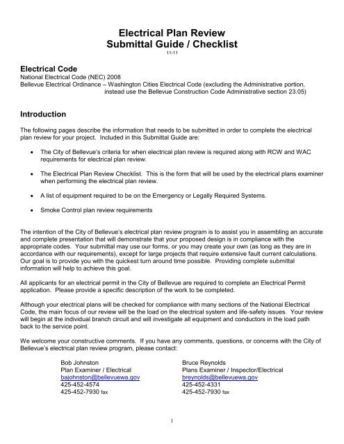
<strong>Electrical</strong> <strong>Plan</strong> <strong>Review</strong><strong>Submittal</strong> <strong>Guide</strong> / <strong>Checklist</strong>11-11<strong>Electrical</strong> CodeNational <strong>Electrical</strong> Code (NEC) 2008<strong>Bellevue</strong> <strong>Electrical</strong> Ordinance – Washington Cities <strong>Electrical</strong> Code (excluding the Administrative portion,instead use the <strong>Bellevue</strong> Construction Code Administrative section 23.05)IntroductionThe following pages describe the information that needs to be submitted in order to complete the electricalplan review for your project. Included in this <strong>Submittal</strong> <strong>Guide</strong> are:The <strong>City</strong> <strong>of</strong> <strong>Bellevue</strong>’s criteria for when electrical plan review is required along with RCW and WACrequirements for electrical plan review.The <strong>Electrical</strong> <strong>Plan</strong> <strong>Review</strong> <strong>Checklist</strong>. This is the form that will be used by the electrical plans examinerwhen performing the electrical plan review.A list <strong>of</strong> equipment required to be on the Emergency or Legally Required Systems.Smoke Control plan review requirementsThe intention <strong>of</strong> the <strong>City</strong> <strong>of</strong> <strong>Bellevue</strong>’s electrical plan review program is to assist you in assembling an accurateand complete presentation that will demonstrate that your proposed design is in compliance with theappropriate codes. Your submittal may use our forms, or you may create your own (as long as they are inaccordance with our requirements), except for large projects that require extensive fault current calculations.Our goal is to provide you with the quickest turn around time possible. Providing complete submittalinformation will help to achieve this goal.All applicants for an electrical permit in the <strong>City</strong> <strong>of</strong> <strong>Bellevue</strong> are required to complete an <strong>Electrical</strong> Permitapplication. Please provide a specific description <strong>of</strong> the work to be completed.Although your electrical plans will be checked for compliance with many sections <strong>of</strong> the National <strong>Electrical</strong>Code, the main focus <strong>of</strong> our review will be the load on the electrical system and life-safety issues. Your reviewwill begin at the individual branch circuit and will investigate all equipment and conductors in the load pathback to the service point.We welcome your constructive comments. If you have any comments, questions, or concerns with the <strong>City</strong> <strong>of</strong><strong>Bellevue</strong>’s electrical plan review program, please contact:Bob JohnstonBruce Reynolds<strong>Plan</strong> Examiner / <strong>Electrical</strong><strong>Plan</strong>s Examiner / Inspector/<strong>Electrical</strong>bajohnston@bellevuewa.govbreynolds@bellevuewa.gov425-452-4574 425-452-4331425-452-7930 fax 425-452-7930 fax1
Requirements for <strong>Electrical</strong> <strong>Plan</strong> <strong>Review</strong>Submit electrical plans for the following installations:Multifamily: 3 units and larger.All work on electrical systems operating at over 600 volts. All educational, institutional, and health or personal care occupancies classified or defined in WAC 296-46B-010(14).All commercial generator or UPS installations.All wind, solar, or fuel cell installations for commercial or residential occupancies.All work in areas determined to be a hazardous (classified) location by the NEC.Existing tenant alterations 2,500 square feet and greater, where the load is increased by 100 amperes orgreater, or the service is altered. This will include sub panels, transformers, UPS systems, andgenerators.Other installations under 2,500 square where there is a significant increase in load (100amps or more) orthe service is altered.If 60% or more <strong>of</strong> lighting fixtures change, contact the electrical plan reviewer.Design, signature, and stamp requirements by a registered electrical engineer are required for the followingelectrical installations:All services or feeders rated 1600 amperes or larger or any special considerations to the service.Installations that require engineering supervision by the NEC.Per the requirements <strong>of</strong> the <strong>City</strong> <strong>of</strong> <strong>Bellevue</strong> ordinances. Ord:23.05.105As required by the building <strong>of</strong>ficial for installations, which by their nature, are complex or hazardous orpose unique design problems.2
<strong>Checklist</strong> – <strong>Electrical</strong> <strong>Plan</strong> <strong>Review</strong>The intent <strong>of</strong> this checklist is to provide a general guideline for electrical plan review. This checklist may not include allitems to be verified for every plan review encountered. This checklist may include more items than a specific set <strong>of</strong>electrical plans may encompass. Please tailor this checklist for the electrical plans submitted and the scope <strong>of</strong> yourparticular job.<strong>Submittal</strong> Items (2 copies <strong>of</strong> each <strong>of</strong> the following)____ <strong>Electrical</strong> plans showing power and lighting for each floor & the location <strong>of</strong> all panelboards.____ <strong>Electrical</strong> plans that are stamped and bear the engineer’s signature who is a Registered Pr<strong>of</strong>essional <strong>Electrical</strong>Engineer by the State <strong>of</strong> Washington.____ <strong>Electrical</strong> panel schedules showing individual loads in VA or KVA and the A.I.C. rating.____ Riser or one-line diagram with wire and raceway size, type, and grounding methods.____ <strong>Electrical</strong> load calculations, including a load summary showing connected loads and all demand/diversity factors.____ Fault current calculations and arc flash calculations through the subpanelboard level.____ Lighting budget calculations per the current adopted Washington State Energy Code.____ Selective coordination information for Emergency, Legally Required, and Elevator systems.____ Arc flash hazard calculations*____ PV system one line and module description sheetOn the 2 <strong>Plan</strong> copies, provide the following information:<strong>Electrical</strong> Load Calculations____ Breakdown <strong>of</strong> connected loads into proper NEC categories (lighting, receptacles, motors,HVAC, kitchen equipment, appliances, etc.)____ NEC demand factors applied to each category <strong>of</strong> load.____ Total connected load in VA or KVA.____ Total calculated load in amps and KVA.____ Panelboard load calculation worksheet completed for all panelboards.____ Starting loads for the worst case (max. starting loads with everything starting that is required to start at the sametime) and any starting variables (s<strong>of</strong>t start, variable frequency drives, etc.) for the Emergency, Legally Required, andOptional Standby systems.Fault Current Calculations on the Riser Diagram____ Submitted on a <strong>City</strong> <strong>of</strong> <strong>Bellevue</strong> form and providing enough information on the riser diagram to verify calculations.Very large projects will require a “Fault Current Summary”.Fault Current Summary must include the following;3
__ The starting nodes for fault current in a cascading format as they relate to the one line diagram.__ The starting fault current at the beginning <strong>of</strong> each conductor.__ The ending fault current at the ending <strong>of</strong> the conductor.__ The conductor’s impedance, size and length.__ The date when the study was performed__ The conduit type (Metallic or Non-Metallic)__ The A.I.C. rating <strong>of</strong> the service, panelboards, and overcurrent devices.____ Utility transformer size in KVA, impedance (%Z), and available fault current.____ Complete the fault current information through the subpanelboard level or provide calculations to below the minimumAIC rating <strong>of</strong> the electrical equipment and overcurrent devices.____ Available fault current shown on the one line diagram for all nodes____ Series rated systems - indicate on the one line or the panel schedules the circuit breaker model numbers for everypanel or switchboard involving a series rated system. Also please provide corresponding series rating charts fromthe manufacturer (with arrows indicating the breaker types) so the series rated system can be verified.This information should be provided in a systematic way as it relates to the one line diagram, down to the point in thesystem that the fault current is less than the fully rated or series rated overcurrent protective device and gear.Riser Diagram (one-line)____ Clearly identify the service point.____ Identify voltages____ Service conduit(s) size & type, number <strong>of</strong> parallel runs, conductor(s) size & type, insulation type, and number <strong>of</strong>conductors.____ Service equipment ampacity, A.I.C. rating and the A.I.C. ratings <strong>of</strong> the overcurrent protection.____ Indicating points (nodes) at line and load points along the one line diagram. The nodes should state the AIC levels atkey points <strong>of</strong> terminations <strong>of</strong> electrical equipment.____ Indication <strong>of</strong> ground fault protection <strong>of</strong> equipment when required.____ Size <strong>of</strong> the grounded service conductor for the maximum unbalanced load.____ Grounding electrode system, including concrete encased electrode, the sizing <strong>of</strong> the grounding electrode conductor,and main bonding jumper for the service equipment.____ Feeder(s) conduit size & type, conductor size & type, and number <strong>of</strong> conductors.____ Type <strong>of</strong> equipment grounding conductor and equipment bonding jumper for feeder(s), size if applicable.____ Panelboard(s) ampacity, A.I.C. rating and overcurrent protection.____ Transformer(s) secondary tap conductor length to overcurrent protective device.____ Grounding electrode system and grounding electrode conductor for transformer(s).____ Size <strong>of</strong> equipment bonding jumper and system bonding jumper for the transformer(s).____ Overcurrent protection <strong>of</strong> transformer(s) complies with NEC 450-3.____ Identify all fuse types (class type)4
Floor <strong>Plan</strong> (Lighting)____ <strong>Electrical</strong> plans denote the type and location <strong>of</strong> all lighting fixtures.____ <strong>Electrical</strong> plans denote all required switch locations.____ Home-run conduit(s) showing size, type, and number <strong>of</strong> conductors.____ Branch circuit(s) properly sized for the load.____ Emergency lighting clearly denoted on plans.____ Unit equipment used for egress lighting complies with NEC 700-12(e).____ Photometric plans for Egress lighting in parking garages. Please provide, for each level <strong>of</strong> building parking,photometric drawings <strong>of</strong> the emergency egress lighting per 2003 IBC section 1006.4, showing 1 ft. candle averageand .1 ft. candle minimum, in a pathway down each drive isle leading to each exit.____ Fill out a lighting summary form.Energy Code Compliance____ <strong>Electrical</strong> plans correspond to the lighting summary; including number and wattage <strong>of</strong> the lighting fixtures, type <strong>of</strong>lighting fixture, the occupancy type, and the watts per square foot allowed.____ Lighting control complies with 1513 <strong>of</strong> the currently adopted Washington State Energy Code. (When required)http://www.neec.net/sites/default/files/neec_codes/WA-EnergyCodes2009.pdf Chapter 15____ Completed copies <strong>of</strong> a lighting summary form. Seehttp://www.neec.net/sites/default/files/neec_codes/forms09/LTG09.4.pdfFloor <strong>Plan</strong> (Power)____ <strong>Electrical</strong> plans denote the location <strong>of</strong> all switchboard(s), panelboard(s), and transformer(s).____ All electrical equipment has working clearance shown as required by NEC Article 110.____ Receptacle outlet locations. Receptacles required by local amendments, for ro<strong>of</strong>tops, for show windows, etc., andas required by NEC 210-52 and <strong>Bellevue</strong> <strong>City</strong> Codes and Ordinances.____ <strong>Electrical</strong> equipment schedule.____ Locations denoted on electrical plans for all motors, compressors, heaters, stationary appliances, etc.____ Homerun conduit(s) showing size, type, and number <strong>of</strong> conductors.____ Branch circuit(s) properly sized for the load.____ Over 112.5 KVA transformers require 1 hour rated construction surrounding them.____ Diagram <strong>of</strong> any transformer vaults including drain pipes, curbing, venting, and fire ratings.5
Panel Schedules____ Panelboard(s) are identified.____ Panelboard busbar rating in amps shown.____ Panelboard voltage rating is shown.____ Main breaker size or main lug only is shown.____ Panel schedule denotes double lugs or feed-through lugs.____ The description or coding is provided for each branch circuit.____ The connected load <strong>of</strong> each branch circuit is shown in VA or KVA.____ The total connected load is shown in VA or KVA.____ The A.I.C. rating <strong>of</strong> the panelboard and overcurrent devices____ Time/current curves showing compliance with the selective coordination requirements for elevators and escalators.This shall be shown to the next common overcurrent device (common to more than one driving machine) abovethe elevator overcurrent device to the level <strong>of</strong> .01 time line.Emergency, Legally Required Standby, or Optional Standby SystemsSee also the section on Equipment System Designations, which follows this section.____ Generator capacity and voltage.____ UPS capacity and voltage.____ System properly sized for the load.____ Indicate that the room, that houses the emergency generating system, has a 2 hour fire rating (NFPA 20)____ Emergency system is totally separate from all other systems.____ Individual transfer switches required.____Grounding electrode conductor properly sized (When required for separately derived systems). State the number <strong>of</strong>“poles” in the transfer switch.____ Signage as required by NEC is denoted on plans.____ Selective coordination <strong>of</strong> overcurrent protective devices for Emergency and Legally Required systems down to the.01 timeline – overlaid time/current curves for each branch from each power source to each branch circuitovercurrent protective device on one sheet.____ Provide 2 hour protection <strong>of</strong> the pressurization fan(s) circuit(s) from the emergency generator to the fan.____ Provide separation <strong>of</strong> the pressurization circuits from other electrical system components6
____ On a high rise building, if there are electrical fire pumps, they need to be calculated into the generator loadcalculation and service load calculationPeak Demand Records (NEC 220.87 or BCC 23.30.220.87)____ Starting and ending dates <strong>of</strong> the metering.____ Highest reading <strong>of</strong> the metering period clearly shown.____ Power factor adjustment shown, when necessary.____ Explain the details <strong>of</strong> seasonal and occupancy adjustment factors.____ Utility demand records or recordings <strong>of</strong> demand metering for the peak period must accompany the submittal.____ Signature <strong>of</strong> the “administrator or engineer” who took the readings.Healthcare Facilities____ Clear definition <strong>of</strong> area use (i.e.: dental, medical, chiropractic, etc.)____ Indicate the ceiling height as it pertains to a Patient Care Area____ Clear definition <strong>of</strong> rooms uses (i.e.: patient room, nurses station, critical care, general care, etc.)____ One line showing separate transfer switches for equipment, life safety, and critical branches____ Ground Fault Protection where required and at the next level as required.____ Wiring methods in patient care areas.____ Selective coordination <strong>of</strong> overcurrent protective devices for the emergency system and subfeeds (where required)Hazardous Locations____ Clear definition <strong>of</strong> area use. Where the classified location starts and stops.____ Wiring methods (type <strong>of</strong> conduit).____ Location <strong>of</strong> sealing fittings where required, and identify the location. (Class 1 Div.1 etc.)____ Depth <strong>of</strong> buried conduit.____ Diagram <strong>of</strong> sump pump showing motors, drain pipes, and all chambers.Smoke Control Systems (high rises and places <strong>of</strong> assembly <strong>of</strong> 1000 persons only)____ Panel schedule (industry standard type) for the emergency panel with connected and demand loads.____ Schedule <strong>of</strong> smoke control components showing equipment, its’ load in amps or volt-amps, conduit typeand size, conductor type and size, and breaker type and size.____ Floor plans showing the location <strong>of</strong> the smoke control components.7
____ Wiring methods for the fire alarm system.____ Show all emergency system wiring methods pertaining to the smoke control.____ Schedule <strong>of</strong> individual smoke control components starting loads that will start at the same time____ Schedule <strong>of</strong> individual smoke control components running loads.____ The total combined loads <strong>of</strong> smoke control components for start up and run (start up and run shownseparately).____ Identify the color marking, protection, and routing <strong>of</strong> the conduit from the generator to the pressurizationfan(s).Arc Flash Calculation____ Provide: (1) the incident energy level calculation in cal/cm squared at 18” from the flash hazard; (2) theflash hazard category, and (3) the flash hazard boundary for each service, distribution board, and panel(4) the date the arc flash calculation was done.Provide this in a cascading format relating to the one line or riser showing:- the device rating and identification- the voltage- the arc gap- the bolted fault current or the available fault currentThe nomenclature used must match the one line diagram for panel/ distribution identification. Please see COBordinance 110.16. http://www.mybuildingpermit.com/Misc/WA%20Cities%20Elect%20Code%2011-12-09.pdfVerification <strong>of</strong> the calculation will not be required where it is stamped and signed by an electrical engineercurrently licensed in the State <strong>of</strong> Washington.An exception allows no flash hazard analysis where all the following conditions exist:- The circuit is rated 240volts or less- The circuit is supplied by one transformer- The transformer supplying the circuit is rated less than 125kvaElectric Vehicle Charging Systems____ Provide the level <strong>of</strong> the supply equipment____ Site or floor plan with location <strong>of</strong> the system including physical protection specifics if required____ Conduit and conductor sizes to the outlets or equipment____ Ratings <strong>of</strong> equipment____ Panel schedule with demand and connected loadPhotovoltaic Systems____ One line diagram <strong>of</strong> the system showing conduit and conductor sizes, connection to the existing service,overcurrent size(s)____ Grounding electrode conductor sizes and location <strong>of</strong> connection(s) to the system____ Where the inverter(s) is physically located____ <strong>Plan</strong> view <strong>of</strong> the array layout on the ro<strong>of</strong> (clearly showing setbacks from the ro<strong>of</strong> edge and peak)____ Spec sheet showing the power ratings etc.____ Penetration location <strong>of</strong> the conductors into the house or attic____ Derating calculation <strong>of</strong> the conductors on the ro<strong>of</strong> and/or in the attic8
Revisions made after <strong>Plan</strong>s approval____ Provide revision symbols (clouds or other effective means) around changes with something to indicatethe date it was changed. These need to stay on the plans throughout the project.____ Provide descriptions <strong>of</strong> specific changes that are proposed in the revised areasEmergency and Legally Required Systems Equipment(what type equipment needs to be on which system)TABLE 403(1)STANDBY (LEGALLY REQUIRED) AND EMERGENCY POWERType <strong>of</strong> EquipmentMaximumTime toEnergizeLoadsMinimum RunTime (Duration)IBC SectionIFC or NFPASectionEmergency Power Systems 1604.2.15 HighrisesExit signs10 seconds2 hours forgenerator power;1011.5.3or 90 minutes forbattery backup604.2.16Undergroundbuildings1011.5.32403.12.6.1Temporary tents,canopies,membranestructures1006.3Exit illumination 10 seconds 8 hours 1006.3604.2.15 Highrises604.2.16Underground9
uildingsAny emergency voice/alarmcommunication including area <strong>of</strong> refugecommunication systems (barrier-free andhorizontal exits)NFPA 7224 hours402.12 Coveredmall buildings403.11 Highrises405.10Undergroundbuildings907.2.1.2Assemblyoccupancies604.2.14 Coveredmall building604.2.15 Highrises604.2.16Undergroundbuildings907.2.1.2AssemblyoccupanciesNFPA 72NFPA 7224 hours403.11 Highrises604.2.15 HighrisesFire detection and fire alarms405.10Undergroundbuildings604.2.16Undergroundbuildings909.20.6.2Smokepro<strong>of</strong>enclosures907907.2.8.3 and907.2.10.2NFPA 72403.11 HighrisesSmoke control systems in high-risebuildings, underground buildings andcovered mall buildings including energymanagement systems are used for smokecontrol or smoke removal60 seconds 2 hours404.6 Atriums405.10Undergroundbuildings909.11909.11 SmokecontrolFire pumps in high-rise buildings andunderground buildings10 seconds8 hours (NFPA20)403.11 Highrises405.10Undergroundbuildings604.2.15 Highrises and NFPA 20604.2.16Undergroundbuildings913.2 All FirePumps10
Smokepro<strong>of</strong> enclosures and elevator shaftpressurization60 secondsfor ventilation 4 hours403.11 Highrises909 and909.20.6.2Any shaft exhaust fans required to runcontinuously in lieu <strong>of</strong> dampersElevator car operation in high-rise andunderground buildings (including controlsystem, motor controller, operationcontrol, signal equipment, machine roomcooling/heating, etc.)Elevator car lighting and communicationsin high-rise and underground buildingsLights, heating, and cooling for buildingfire command center and mechanicalequipment rooms serving the firecommand center60 seconds 4 hours 71660 seconds 4 hours 300310 seconds 4 hours 300360 seconds 24 hours604.2.15 Highrises604.2.16Undergroundbuildings604.2.15 Highrises604.2.16Undergroundbuildings604.2.19 Elevators604.2.15 HighrisesPower (other than lights, heating andcooling) for building fire command center60 seconds 4hoursMechanical and electrical systemsrequired by IFC 27 (hazardous materialsincluding UPS rooms)60 seconds 4 hours Article 27Legally Required Standby 1Pressurization equipment for low-risebuildingsExhaust fans for any loading dock locatedinterior to a building60 seconds 4 hours60 seconds 4 hours909909.20Operation <strong>of</strong> elevators used as accessiblemeans <strong>of</strong> egress in low-rise buildings(including car lighting, communications,60 seconds 4 hourscontrol system, motor controller, operation1007.4 and .53003604.2.19 Elevators1007.4 and .511
control, signal equipment, machine roomcooling/heating, etc.)Fire pumps in low-rise buildings 10 seconds 8 hours913.2 and NFPA20Transformer vault ventilation equipment 60 seconds 4 hoursHeat tape for sprinkler lines and heating insprinkler riser roomsFuel pump system for any legally-requiredsystem60 seconds 24 hours60 seconds 4 hoursSewage disposal pumps 60 seconds 4 hoursTABLE 403(1) FOOTNOTES:1. The fuel pump and associated systems for the emergency or legally required generator shall be provided with powerfrom the generator to maintain fuel supply.FormsCopies <strong>of</strong> these forms are found on the following pages:Fault Current Calculation FormSample One-Line DiagramSample Single-Phase Panel ScheduleSample 3-Phase Panel ScheduleGenerator Calculation FormSample Fault Current Calculation Summary FormPhotovoltaic System One Line and Spec SheetYour submittal may use our forms, or you may create your own (as long as they are in accordance with ourrequirements), except for large projects that require more extensive fault current calculations.12
Reminders and Notes- The seismic bracing calculations and diagrams by engineering standards submitted to the building reviewerfor equipment between 75 lbs and 400 lbs. at 4’ or more above the floor or ro<strong>of</strong> level, or equipment more than400lbs. at ground level or any height.- NEC 110.16 & NFPA 70E field marked warning labels to warn workers (qualified) <strong>of</strong> the potential electricflash hazards.- Washington Cities <strong>Electrical</strong> Code 110.16 A plate or label is required and shall include the flash hazardcategory, the incident energy level in cal/cm(squared) at 18 inches from the flash hazard, and the flash hazardboundary and the date the arc flash calculations were done.- <strong>Bellevue</strong> Fire Department requires the circuit and control wiring going to the stairway and elevator shaftpressurization fans be separate and protected from all other systems in the building. They are required to beprotected by a 2 hour rated assembly. They shall be separated from the emergency system from the transferswitch (if specific to the pressurization fans) or the first distribution point after the transfer switch to the fans.- Revisions to the original approved plans need to be clouded and dated indicating when the change tookplace. The revisions need to be accompanied by a narrative explaining what the change is particular to eachcloud.13
Fault CurrentCalculation FormPermit Number:Date:Project Name:Contractor Name:The following fault current calculation form must be completed and submitted prior to service approval. See instructions andimpedance table on reverse side. Continue these steps until each panel has been addressed or the fault current is below theminimum equipment rating.A. UTILITY TRANSFORMER Value Total FaultImpedanceCurrent1. Rated Capacity ________________KVA2. Secondary Voltage ________________V ____________3. Nameplate % Impedance ________________%Or4. Transformer Short Circuit Amps ________________Amps5. Ohmic Impedance (V (see V defined in step 1 page 2) divided by the short circuit amps)____________Ohms (step #1)B. SERVICE CONDUCTORS1. Conductor Size ________________ Type________(CU or AL)2. Length ________________Ft3. Type <strong>of</strong> Conduit (metal or PVC) ________________4. Impedance per 1000’ ________________Ohms per 1000’5. Number <strong>of</strong> Parallel Runs ________________6. Conductor Impedance (Imp. per 1000’ x length divided by (# <strong>of</strong> parallel runs x 1000))______________Ohms (step #2)7. Total Impedance to Source (A5 + B6) ______________Ohms8. Fault Current to Load Terminals (V (see V defined in step 1 page 2) divided by B7) _____________Amps (step #3)C. SERVICE ENTRANCE EQUIPMENT1. Equipment Rating ________________Amps2. Interrupting Rating _____________A.I.C.D. FEEDER CONDUCTOR1. Conductor Size _________________ Type _________(CU or AL)2. Length _________________Ft3. Type <strong>of</strong> Conduit _________________4. Impedance per 1000’ _________________Ohms per 1000’5. Number <strong>of</strong> Parallel Runs _________________6. Conductor Impedance (Imp. Per 1000’ x length divided by (# <strong>of</strong> parallel runs x 1000))______________Ohms7. Total Impedance to Source (B7 + D6) ______________Ohms8. Fault Current at Load Terminals (V (see V defined in step 1 page 2) divided by D7)______________AmpsE. FEEDER PANEL(step #3)1. Equipment Rating _________________Amps2. Interrupting Rating ______________A.I.C.14
Fault Current Calculation Form, p.2TRANSFORMER REPLACEMENTS: Replacements that result in a higher possible fault current, than that <strong>of</strong> the existingequipment, SHALL be addressed to this department, prior to reconnection <strong>of</strong> existing service equipment.-------------------------------------------FAULT CURRENT CALCULATION INSTRUCTIONS-------------------------------------(STEP #1)Secondary Transformer (I.C. Rating) at its rated voltage, calculate Z-ohms as follows:Transformer Z-ohms = V ( “V” as defined below)Short Circuit CurrentV120/240V 1 3-wire 120208Y/120V 3 4-wire 120240 Delta 3 4-wire 140480Y/277V 3 4-wire 277480 Delta 3 3-wire 277(STEP #2) (Using Cable Impedance Data Table Below)Conductor Impedance =(impedance per 1000’) X length1000 X number <strong>of</strong> parallel runs(STEP #3)Service I.C. = “V” (total Z = transformer Z + cable Z)Total Z(STEP #4)Subpanel I.C. = “V” (total Z = transformer Z + cable Z)Total ZNote:Continue these steps until each panel has been addressed or the fault current is below the minimum equipment rating.CABLE IMPEDANCE DATA (ohms per 1000 feet)Conductors Copper AluminumAWG or KCMILMagneticDuctNon-MagneticDuctMagneticDuctDuctNon-Magnetic#2 0.20 0.19 0.32 0.32#1 0.16 0.15 0.25 0.25#1/0 0.12 0.12 0.20 0.20#2/0 0.10 0.10 0.16 0.16#3/0 0.079 0.077 0.13 0.13#4/0 0.063 0.062 0.10 0.10250KCM 0.054 0.052 0.086 0.085300KCM 0.045 0.044 0.072 0.071350KCM 0.039 0.038 0.063 0.061400KCM 0.035 0.033 0.055 0.054500KCM 0.029 0.027 0.045 0.043600KCM 0.025 0.023 0.038 0.036750KCM 0.021 0.019 0.031 0.02915
Sample 1Ø Panel Schedule17
Sample 3Ø Panel Schedule18
Utility XFRM Voltage AIC (Start) Date Project Title: <strong>City</strong> <strong>of</strong> <strong>Bellevue</strong> Permit Number: PageConductor Conductor Conductor Description: Raceway: AIC AIC AIC CheckedFrom To Size Type (CU/AL) Length/Ft. Imp./1K Ft. Qty./Ph. Metal/PVC Start End Equip/Brkr** The AIC rating <strong>of</strong> the equipment is the lowest value between the breaker and equipmentPlease confirm that the AIC values are shown on the one line/riser diagram20