Electrical Plan Review Submittal Guide / Checklist - City of Bellevue
Electrical Plan Review Submittal Guide / Checklist - City of Bellevue
Electrical Plan Review Submittal Guide / Checklist - City of Bellevue
You also want an ePaper? Increase the reach of your titles
YUMPU automatically turns print PDFs into web optimized ePapers that Google loves.
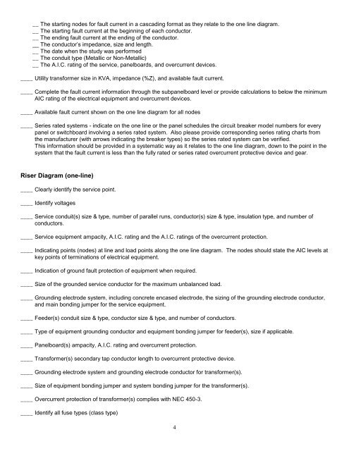
__ The starting nodes for fault current in a cascading format as they relate to the one line diagram.__ The starting fault current at the beginning <strong>of</strong> each conductor.__ The ending fault current at the ending <strong>of</strong> the conductor.__ The conductor’s impedance, size and length.__ The date when the study was performed__ The conduit type (Metallic or Non-Metallic)__ The A.I.C. rating <strong>of</strong> the service, panelboards, and overcurrent devices.____ Utility transformer size in KVA, impedance (%Z), and available fault current.____ Complete the fault current information through the subpanelboard level or provide calculations to below the minimumAIC rating <strong>of</strong> the electrical equipment and overcurrent devices.____ Available fault current shown on the one line diagram for all nodes____ Series rated systems - indicate on the one line or the panel schedules the circuit breaker model numbers for everypanel or switchboard involving a series rated system. Also please provide corresponding series rating charts fromthe manufacturer (with arrows indicating the breaker types) so the series rated system can be verified.This information should be provided in a systematic way as it relates to the one line diagram, down to the point in thesystem that the fault current is less than the fully rated or series rated overcurrent protective device and gear.Riser Diagram (one-line)____ Clearly identify the service point.____ Identify voltages____ Service conduit(s) size & type, number <strong>of</strong> parallel runs, conductor(s) size & type, insulation type, and number <strong>of</strong>conductors.____ Service equipment ampacity, A.I.C. rating and the A.I.C. ratings <strong>of</strong> the overcurrent protection.____ Indicating points (nodes) at line and load points along the one line diagram. The nodes should state the AIC levels atkey points <strong>of</strong> terminations <strong>of</strong> electrical equipment.____ Indication <strong>of</strong> ground fault protection <strong>of</strong> equipment when required.____ Size <strong>of</strong> the grounded service conductor for the maximum unbalanced load.____ Grounding electrode system, including concrete encased electrode, the sizing <strong>of</strong> the grounding electrode conductor,and main bonding jumper for the service equipment.____ Feeder(s) conduit size & type, conductor size & type, and number <strong>of</strong> conductors.____ Type <strong>of</strong> equipment grounding conductor and equipment bonding jumper for feeder(s), size if applicable.____ Panelboard(s) ampacity, A.I.C. rating and overcurrent protection.____ Transformer(s) secondary tap conductor length to overcurrent protective device.____ Grounding electrode system and grounding electrode conductor for transformer(s).____ Size <strong>of</strong> equipment bonding jumper and system bonding jumper for the transformer(s).____ Overcurrent protection <strong>of</strong> transformer(s) complies with NEC 450-3.____ Identify all fuse types (class type)4


