3DQuickMold Training Manual - 3D CAD/CAM Design Software
3DQuickMold Training Manual - 3D CAD/CAM Design Software
3DQuickMold Training Manual - 3D CAD/CAM Design Software

Create successful ePaper yourself
Turn your PDF publications into a flip-book with our unique Google optimized e-Paper software.
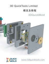
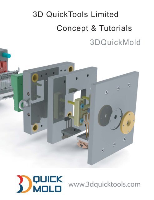
<strong>3D</strong> QuickTools LimitedConcept & Tutorials<strong><strong>3D</strong>QuickMold</strong>MOLDwww.3dquicktools.com
ContentsSOFTWARE INTERFACE .............................................. 5CHAPTER 1. SET PROJECT ....................................... 8CHAPTER 2. SHRINKAGE FACTOR ........................... 8CHAPTER 3. QM-SURFACEPARTING ........................ 93.1 Workpiece ..................................................................................................................... 103.2 Search Cavity/Core faces ............................................................................................ 123.3 Extract parting lines .................................................................................................... 143.4 Create parting surface ................................................................................................. 163.5 Create Cavity/Core ...................................................................................................... 193.6 Save Assembly .............................................................................................................. 19CHAPTER 4. QM-SOLIDPARTING ............................ 224.1 Workpiece ..................................................................................................................... 224.2 Solid Patch .................................................................................................................... 234.3 Parting Surface............................................................................................................ 264.4 Solid Attribute .............................................................................................................. 274.5 Define Parting Surface ................................................................................................ 274.6 Create Cavity/Core ...................................................................................................... 294.7 Paste Bodies .................................................................................................................. 304.8 <strong><strong>3D</strong>QuickMold</strong> Update ................................................................................................. 314.9 Continuous Edges......................................................................................................... 314.10 Box Selection................................................................................................................ 321
4.11 Face Search .................................................................................................................. 334.12 Quick Replace.............................................................................................................. 354.13 Show/Hide Bodies........................................................................................................ 35CHAPTER 5. SUBINSERT MANAGER ...................... 365.1 Components navigator................................................................................................. 375.2 body ............................................................................................................................... 385.3 holder ............................................................................................................................ 435.4 Assembly ....................................................................................................................... 475.5 Tools ............................................................................................................................. 49CHAPTER 6. FEED MANAGER ................................. 516.1 Component Navigator ................................................................................................ 516.2 Tools .............................................................................................................................. 526.3 Path............................................................................................................................... 556.4 Runner ......................................................................................................................... 596.5 Gate design ................................................................................................................... 63CHAPTER 7. LAYOUT MANAGER ........................... 66CHAPTER 8. MOLDBASE MANAGER ...................... 73CHAPTER 9. EJECTOR WIZARD ............................. 829.1 Component navigator .................................................................................................. 829.2 Position .......................................................................................................................... 829.3 Library .......................................................................................................................... 869.4 Edit ................................................................................................................................ 919.5 Tools .............................................................................................................................. 922
CHAPTER 10. COOLING WIZARD ............................ 9810.1 Component Navigator ............................................................................................ 9810.2 Path............................................................................................................................ 9810.3 Parameters ................................................................................................................. 10610.4 Accessory ................................................................................................................... 11010.5 Tools ........................................................................................................................... 110CHAPTER 11. LIBRARY MANAGER ...................... 11211.1 Adding Screw ........................................................................................................ 113CHAPTER 12. SLIDER WIZARD ............................. 11812. 1 Component vavigator ........................................................................................... 11912.2 Body ........................................................................................................................ 11912.3 Component............................................................................................................. 12212.4 Assembly ................................................................................................................ 12412.5 Tools ...................................................................................................................... 125CHAPTER 13. LIFTER WIZARD ............................. 12713.1 Component navigator ............................................................................................ 12713.2 Body ........................................................................................................................ 12813.3 Component............................................................................................................. 13513.4 Assembly ................................................................................................................ 13713.5 Tools ........................................................................................................................... 137CHAPTER 14. ELECTRODE MANAGER ................ 13914.1 Component Navigator .............................................................................................. 13914.2 Body ......................................................................................................................... 1403
14.3 Holder..................................................................................................................... 14514.4 Assembly ................................................................................................................ 14814.5 Tools ....................................................................................................................... 149CHAPTER 15. BOM MANAGER .............................. 150CHAPTER 16. QM- TOOLS ..................................... 15116.1 Part Information .................................................................................................. 15116.2 Cut Relationship................................................................................................... 15216.3 Multiple copy ............................................................................................................. 15216.4 Boolean Operation ............................................................................................... 15216.5 Classify Component .............................................................................................. 15316.6 Create Pocket ........................................................................................................ 15416.7 Pocket Clearance ........................................................................................................ 15516.8 Pocket corner ......................................................................................................... 15516.9 Set configuration ....................................................................................................... 15616.10 Save project ............................................................................................................ 15816.11 Favorite View ......................................................................................................... 158CHAPTER 17. QM-DOCUMENT .............................. 1584
Preparation<strong><strong>3D</strong>QuickMold</strong> is a professional plastic mold design software seamlessly integrated withSolidworks. This manual is based on the Solidworks 2011.Please do the following after the installation:1. Click Tools -> Options->Add-Ins, make sure <strong><strong>3D</strong>QuickMold</strong>2011 is checked2. <strong><strong>3D</strong>QuickMold</strong> advises the user to start project with new SolidWorks part. To do this, youcan open a new part, insert the original plastic model file. This can retain thecompleteness and independency of data of the original part. Adjust a suitable origin andposition. The default mould open direction of <strong><strong>3D</strong>QuickMold</strong> is the Z-axis.<strong>Software</strong> InterfaceThe new user interface looks like the following picture shown. Similar to other SolidWorks UIs,you can re-arrange those icons as you like.1. <strong><strong>3D</strong>QuickMold</strong> pull-down menuClick <strong><strong>3D</strong>QuickMold</strong>11 in the menu bar, pull down menu pops out as follows:5
Each mold design module is listed below:• Set Project:Set the current working models• Shrinkage Factor:Scale the part to allow for shrinkage• QM-SurfaceParting:Surface-based parting• QM-SolidParting:Solid-based parting• Insert Wizard:Sub-insert design• Feeding Wizard:Runner and Gate design• Layout Manager:Arrange the core/cavity layout• Moldbase Manager:Load and edit mold base• Ejector Wizard:<strong>Design</strong> ejectors• Cooling Wizard:Cooling channel• Library Manager:Standard libraries for mold design• Slider Wizard:Slide design• Lifter Wizard:Lifter design• Electrode Wizard:Electrode design• Bom Manager:Bill of materials----------------------------------------------------------------• QM-Tools:Effective tools for mold design• QM-Documents:Activate working models2. <strong><strong>3D</strong>QuickMold</strong> Command ManagersThe corresponding command groups of the above modules are listed below:Surface parting groupSolid parting groupMold design module groupTools group for mold design3. <strong><strong>3D</strong>QuickMold</strong> Toolbars6
Toolbars are available as well, they can be shown up or hidden as needed.They are QM-SolidParting, QM-SurfaceParting, QM-Tools, QM-Wiards and QM-Documentsrespectively.4. <strong><strong>3D</strong>QuickMold</strong> Pop-up MenuIf face is selected, right-click the mouse button, a pop up menu is displayed as following.It is used to set or reset the parting surface.7
Chapter 1.Set ProjectThis is not a mandatory step for <strong><strong>3D</strong>QuickMold</strong> now. Without setting the working project, youstill can use most functions provided in the system, it is mainly used in some particular cases.For the following purposes, you may set your project using the function: If the core/cavity was done by other <strong>CAD</strong> system and imported into SolidWorks fordownstream design or even done by SolidWorks alone, you can use this UI to set yourplastic part, core/cavity to let <strong><strong>3D</strong>QuickMold</strong> to recognize them.For mutilple mold design projects at the same SolidWorks envioroment, you need setyour current working models such as plastic part, core, cavity, product assembly, Projectassembly to tell the system which project you are working on.Chapter 2.Shrinkage FactorEvery plastic material has a shrinkage factor assigned to it, the part hasto be enlarged proportionally to compensate the contraction。Click on,the following page pops out.Different scale factor can be set to the product.The product can be scaled along x, y, z direction.The product can be scaled about the Centroid, the Origin, or acoordinate system selected.8
Different plastic material is available under Resin type. The material database is located at theinstallation folder\ res \ shrinkage factor.txt and it can be edited. Below shows the adding of anew material in the shrinkage factor.txt that is highlighted in red.On the “Product Shrinkage” dialog, under resin type, the newly added resin can be found.Chapter 3.QM-SurfacePartingThis surface-based parting module basically aims to simplify a lot of native SolidWorks partingprocess such as parting-line and shut-off creations.9
3.1 WorkpieceWorkpiece is used to determine the core/cavity size, it is advised to be done before partingsurface。Click on,<strong><strong>3D</strong>QuickMold</strong> will show the minimum size of the current part, thedefault Length, Width and Height are set automatically, the preview as follows.At Definition group, size of work piece and its relative position could be edited.:Length of work piece:Width of work piece:Height of work piece:Offset value along X direction10
:Offset value along Y direction:Offset value along Z directionIf Corner position option is checked, the position of the workpiece relative to the coordinatesystem is shown. The workpiece can be offset by changing the value of x, y, z.The value in Corner position is the minimum value of the workpiece in the x, y, z direction.After setting is completed, click OK.6 reference planes with the workpiece as border are created.(the first five reference planes arehidden,Mold Front is shown; the distance between Mold Front and sketch is the height of theworkpiece, the size of the whole work piece is visualized.A sketch of Block Sketch with Mold Back as reference is also created,This block sketchdetermine the size of the final size of the core and cavity, the dimension of the sketch is thedimension of the projected image of the workpiece on the xy plane.11
3.2 Search Cavity/Core facesThis is a tool for searching faces, by selecting boundary condition and a seed face to propagatethe search of faces on the part surface.This function is similar to the SolidWorks Draft analysis, but additional boundary condition isused to control the researching result.• Edit color:Specify the core/cavity color,by default, green for cavity, red for core.Specify pull direction:If the pull direction is specified, only the faces that satisfy the molddraft condition will be selected.Using this function, only the connected faces are selected and can be knitted together.12
Reverse selection:Reverse the mold open directionFrom: (seed face)To:(Boundaries below): Boundaries could be edge or face type, by selecting the boundaries, thesearching faces will not cross them.In the following sample,specify direction and seed face, click, result as below.Further action:Apply color:Add color on the selected facesRemove color:Remove face color on the selected facesNone:Select the faces alone, user can do any further operation by theirselves.Additional cavity faces:Basides the faces selected automatically, can pick up more faces.Click,all faces on the model are classfied as core or cavity faces by different color.13
3.3 Extract parting linesOnce the core/cavity faces are fully defined, based on the face color, system can use this functionto extract the parting lines and hole loops. Then, this function will try to use Shut-off surface topatch the holes. Under some situations, Shut-off may fail to be created.Exchange cavity/core face: Exchange the face color between cavity and core.Quick cavity:All undefined faces are specified as cavity faces, color changed accordingly.Qucik core:All undefined faces are specified as core faces, color changed accordingly.Extract boundaries:Extract the parting lines and hole loops for shut-off surface.14
Click, All boundary edges will be extracted and classify into outer loop and innerloops automatically based on the current core/cavity faces’ color information:Click ,The outer loops will be set as parting line and inner loops will be used to shut-off theholes on the plastic part。If successful, the following picture will be shown onthe feature tree .Whether Shut-off surface created or not, greatlydepends on the complexity of the holes on the part,do check the feature tree and the Surface Bodiesfolder before you proceed to the next step.By right, the Cavity Surface Bodies and Core Surface Bodies should be under the SurfaceBodies folder. If cannot find them, please do the shut-off manually in SolidWorks. For thecomplex hole, you can choose the no-fill option rather than contact or tangent.15
Note: The Shut-off surface feature can be used once only in SolidWorks. For the complex part,to split the core/cavity using SolidWorks way, user can create their own surface bodies to patchthe holes, and manually move those surface bodies to Parting Surface Bodies folder.3.4 Create parting surfaceThis command is used to create parting surface,if nothing is pre-selected, the SolidWorksParting Surface interface will pops up.If parting lines exist, it is pre-selected automatically.All surface-creating features in SolidWorks can be used to generate parting surface, the mostcommon ones are Parting Surface, Ruled Surface, Extrude Surface, Loft Surface and PlanarSurface.If a reference plane is pre-selected, the following dialog will pop up.16
Extrude surface:Select the reference plane and some edges. The edges will be converted tosketch segments and extrude to the body that the edges lie on.Loft surface:Select the reference plane and some edges. For loft surface, the edge could beeither a solid body edge or surface body edge.17
Radiate surface:Select the reference plane and some edges to create the radiate surface. Mostof time, ruled surface and parting surface are better than radiate surface in mold design.Planar surface:Select the reference plane and some edges to create the planar surface.This option can simplify the planar surface creation. Some addtional edges are crated to enclosea closed planar area.18
3.5 Create Cavity/CoreSupposing the parting line, parting surface and core/cavity surface bodies are all createdsuccessfully, clickwill create the core/cavity automatically.So far, all surface parting related functions are basically SolidWorks features but many steps aresimplified a lot to improve the software performance.3.6 Save AssemblySave the core/cavity bodies into an assembly called product assembly, under this assembly, theoriginal plastic part, the core and cavity are separated components.• Prefix:By default, it is the part name• Assembly name:Assembly name for the product assembly• Cavity name:Cavity name• Cavity material:Can input or select a material name fromthe drop-down list below.• Core name:Core name• Core material:Can input or select a material name fromthe drop-down list below.• Show/hide solid:Show or hide the selected bodies19
Please ensure the pre-selected core/cavity bodies are correct, if not, please pick up themmanually in the graphic area or body folder.• Sidecore name:Name for side coreSelect the side core bodies• Sidecore material : Input or select• Insert name:Name for insert componentSimilar to the side core selection, pick up the insert bodies manually.• Insert material:Input or select.Advanced option:20
Top/Bobbom Face : Specify the top or bottom faceto create the CoreSheet for ejector trimming• Select top face:Top face on cavity• Select bottom face:Bottom face on coreStockSize : Those information will be savec into thefile properties for future use such as BOM.Unit:Unit for the following size.Decimal places:Precision Cavity size:Length of the cavity workpiece:Width of the cavity workpiece:Height of the cavity workpiece Core size:Length of the core workpiece:Width of the core workpiece:Height of the core workpieceThe system will calculate the minimum workpiece for the core/cavity based on the splitcore/cavity bodies and show them as default values for L, W, H. However, users can take theallowance into consideration and input their own values.21
Chapter 4.QM-SolidPartingSolid Parting is a different parting concept from the Surface parting. Here, we will use solidbodies to patch the holes on part, use solid bodies to simplify the parting surface sometimes.4.1 WorkpieceWorkpiece function is used to define the work piece for machine core/cavity insert.Click,<strong><strong>3D</strong>QuickMold</strong> will define the default dimension of the workpiece based onthe body size and create a preview.22
Check Product assembly, <strong><strong>3D</strong>QuickMold</strong> will create a * Assembly.sldasm assembly file (* is thename of the plastic part). The number of Sidecore and Insert can be defined here. It can bedefined in the Product Assembly which will be mentioned later.After setting is completed, click OK,6 reference planes with the workpiece as border arecreated.(the first five reference planes are hidden,Mold Front is shown; the distance betweenMold Front and sketch is the height of the workpiece), A sketch of Block Sketch with Mold Backas reference is also created,This block sketch determine the size of the final size of the core andcavity. Click again can edit the existing work piece.4.2 Solid PatchThis function is used to create the solid bodies to patch holes on part.Extend to next: Extend the selected planar face and terminateonto the part. This function equals the Extrude feature but multipleselections are supported.Extend to plane: Extend the selected face to specified plane23
Extend by distance: Extend the selected planar to a certaindistance.Thicken face: A thicken body is created on the selected facesBy default, all holes on the selected face are removed, for someexceptions, using Excluding loops, select the edge of the holes,those selected holes won’t be removed and remain on thethicken body when completed.A sample shown below, there are holes on the selected face in green, selects the edge on thebottom of the boss, click OK, the thicken body is created as the following picture shown.24
Multiple face: Fill the hole forming by multiple faces. For example, the hole shown below.Circular edges: select the circular edges on the body, a cylindrical body is built with radius0.1mm larger than the radius of the edge.25
Revolved faces: Select revolved faces, this function combines a serial of Solidworks features toform a solid body to fill up the hole.Untrim surface: Some revolved face should untrim the underlying surface first, and then createthe solid body based on the untrimmed one. The below picture shows a very common situation.4.3 Parting SurfaceThis function is normally followed by the Workpiece creation. The six reference planes are usedas references to build the parting surface.User can use any Solidworks surface feature to create the surface and specify them as partingsurface later on. Using this function, the created surface will change to yellow color and set asparting surface automatically.Clickparting for details., the following dialog pops up, please refer to the function in Surface26
4.4 Solid AttributeThis tool is used together with “Paste body” for Solid parting approach in <strong><strong>3D</strong>QuickMold</strong>.Running this function, system will assign the attributes on the selected bodies.Cavity patch: Specify the selected solid body as cavitypatch body, a patch body normally will be pasted to the cavityside later on.Cavity insert: Insert body on cavity sideCore patch: Patch body on core sideCore insert: Insert body on core sideSidecore block: Sidecore bodyGates:Gate bodyUndefined bodies:Select all bodies undefined so farDefined bodies:Select all bodies defined alreadyFeature:When a feature consists of multiple bodies, pick upthis feature on the feature tree, all bodies created by this featurecould be selected automatically.Check: Check the existing bodies for specified type.Reset: Reset the attribute on the body. If wrong attribute isassigned on the body, you need to reset it first, and then assignthe new attribute again.4.5 Define Parting Surface27
There are two ways to define the parting surface: Select face in the graphic or surface body under the body folder and right-click the mousebutton, Set parting surface will do this. Click , the following dialog pops out, pick up the face one by one,finally, click OK to confirm your selection, the selected face will become yellow.28
4.6 Create Cavity/CoreThis function is mainly used:as the final stage of the automatic split core/cavityto regenerate the core/cavity when the parting surface ischanged.to add additional side cores or sub-insert parts to theproduct assemlbyClick, the property manager pop out.If the number of Sidecore and Insert of the workpiece is notspecified before,specify it in the Product assembly。Assembly name:Input name of the product assembly. If thatassembly is already generated in Workpiece, the name field willbe greyed out.Sidecore name:Input the name of the side core, the numberinside the bracket indicate the existing number of sidecore. If thenumber of sidecore is not sufficient, add by selecting a suitablenumber.Insert name:The configuration of Insert is the same assidecoreSketch:Select sketch of the workpiece,<strong><strong>3D</strong>QuickMold</strong> will select the sketch of Block Sketchgenerated in workpiece.Plane:<strong><strong>3D</strong>QuickMold</strong> will automatically select the Mold Front generated in Workpiece as thereference plane;This plane will be used to define the end condition of extrude feature.Custom sketch and plane can also be used. It is recommended to use the default selection.Cavity setting:Cavity name:Input the name of the cavityRe-generate: When the parting surfaces are changed, you need to re-generate the cavity.Core setting: Similar to the Cavity setting butTips: After Re-generate, the newly generated part will replace the previous core/cavity, anyspecial feature on the previous core/cavity will not pass to the new one.29
After the setting is completed, click OK,<strong><strong>3D</strong>QuickMold</strong> will generate * core.sldprt,*cavity.sldprt and re-build * assembly.sldasm, *side core1.sldprt, *side core2.sldprt…for sidecore, *Insert1.sldprt and *Insert2.sldprt…for Insert component.4.7 Paste BodiesNormally, this function is used together with Solid AttributeThe bodies with attribute defined in Solid Attribute can be pasted from the plastic part to targetcomponents such as core/cavity, sub-insert or sidecores in batch.Select component:Select the target component where the bodieswill be pasted.Select bodies:Select the bodies to paste.Select product:By default, the plastic part is automaticallyselected, bodies defined as side cores will be listed out for yourselection.Sidecore list:All Side core bodies defined in the product are listedout here.Cavity bodies:Click this button, the cavity blocks will beselected,they will be pasted to the cavity part.;Core bodies:Click this button, the core blocks will be selected,they will be pasted to the core partSidecore file one by one.Associated:Turn on and turn off the associativity.Auto Sidecores:Click this icon, the following dialogue box popout, click Yes to paste defined sidecore bodies onto the existing30
Auto Inserts:Click this icon, the following dialogue box pop out, click Yes to paste definedinsert bodies onto the existing Insert file one by one.Finally, Click OK,the bodies will then be pasted to the selected target component.4.8 <strong><strong>3D</strong>QuickMold</strong> UpdateClickto update the part or assembly if the cavity patch body, cavity insertbody, core patch body, or core insert body is changed.4.9 Continuous EdgesThis is a tool for searching of edges, through difference combination ofselected faces and edges(there are three combination,three corresponding usage),quicksearches of all desired edges, select face first then edges,click Continuous Edges to proceedwith the search.Usage 1:select one face (or more than one continuous face), on this faces select an edge,clickContinuous Edges,<strong><strong>3D</strong>QuickMold</strong> will search for a close loop among multiple faces. Normally,the parting lines are many but they belong to a few faces only, in this case, to avoid missing thesmall edge selection, this tool could be used.Select two faces and one edge as the following picture shown. Click Continuous Edges, theresulting edges are highlighted as below. It is a complete loop.31
Usage 2:select one or more adjacent faces, on this faces select any two edges, clickContinuous Edges,<strong><strong>3D</strong>QuickMold</strong> will search a partial open loop, the direction of the openloop will follow the first picking up point on the first edges.If the picking up point on the first selected edge is near to the top end, the partial open loop isselected as the below picture shown.4.10 Box SelectionThis is a tool for searching of faces,through a space box defined by someentities, all the faces fully enclosed by the box will be selected,it is commonly used insearching faces for the side core, inserts and electrode. Using these tools, users can avoid themissing of small faces by mouse click selection.32
Define box:define the box dimension,entities can be vertices,edges and face.Uniform clearance:the Uniform clearance will be added in thedimension of the box in the six direction of X,-X,Y,-Y,Z,-Z, non-uniform clearance could also be added.:Clearance valueInclude cross faces:Including faces that are crossing the selectionbox.Solid body:ct faces on solid bodies only.Sheet body:Select faces on sheet bodies only.All bodies:Select faces both on sheet bodies and solid bodiesSearch: Start searching the faces under the current conditions.Knit result:If this option is checked, the selected faces will beknitted after OKWhen set up is done,click OK,<strong><strong>3D</strong>QuickMold</strong> will search andhighlight all the faces that fulfill the search criteria.4.11 Face SearchThis is a tool for searching faces, by selecting boundary condition and a seedface to propagate the search of faces on the part surface.33
Searching sample with different optionFrom: (seed face)Search inwards:Search inward from the seed face’s innerloop until it is bounded by the boundary edges.Search outwards:Search outward from the outer edge of theseed face until it is bounded by the boundary edges.Search both sides:Search both inward and.To be boundaries below:Boundary edges:Click this button, the parting lines that havebeen set will be selected automatically into the list box. Theboundary edges can also be selected manually. Boundary caneither be edges or faces.Specify pull direction:If the pull direction is specified, onlythe faces that satisfy the mold draft condition will be selected.Reverse pull direction: If the pull direction shown is not correct,click this button.Include seed face:Include the seed face in the result list.Search: Start searching faces that fulfill the search criteria.Reverse selection:Reverse the search list, this means allunselected faces on the part will be selected while the highlightedones will be removed from the list.Max face number:Specify the maximum face number to beselected. When the boundary edges are not defined correctly toenclose a regional area, search faces will result in all faces on thepart selected, in this case, max face number can help user to findout the open edges among the boundary edges.Search outwards,Search inwardsSearch both sidesSelect a seed face and specify the pull direction, the face searching can be carried out.34
4.12 Quick ReplaceTo use “Quick replace”, two faces on different solid bodies could be selected, the system willalways use the face on the plastic part to replace the one on other bodies. This means the originalpart won’t be changed whatever the order users pick up the faces.4.13 Show/Hide Bodies35
Select a face or edge on body, click this function, the underlying body will be hidden, if nothingselected, click this function again, all hidden bodies will be shown again.Chapter 5.SubInsert ManagerUsuallly, there are two methods for sub-insert desgin <strong>Design</strong> sub-insert on product, this step is done before mold spliting <strong>Design</strong> sub-insert on core or cavity, it is done after mold splitingClick on to access Subinsert design dialog.Typical design procedures as follows:Define sub-insert body => Create holder => Save sub-insertOn each wizard page, there are some utilities for users to dosome basic design jobs quickly. By pre-selecting some edge, faceor sketch, those functions can be performaned directly withoutfurther dialog shown up.If a design job needs a few parameters to key in and previewis required, you can click “Advanced” button on the bottom of thewizard page.Normally, when you hover the mouse cursor over the bitmapbutton, there is a tooltips to show you what this button means.Most of time, if don’t know how to use those functions,simply click on the button without any selection, there is aninformation dialog pops out to show you how to use it.36
5.1 Components navigatorIf working at assembly model, the assembly and all children components are listed as a tree tohelp user to navigate those models conveniently. Right-click mouse at selected item, there aredifferent Open mode for you to choose. Open part is to activate the selected model.If select Show neighbor components,while the part opens, its neighbor components under theassembly will be displayed as temporary bodies.Different from the Show as neighbor components, if Show as assembly is selected, all childrencomponents are shown as temporary bodies instead of neighbor components alone.Hide pseudo components will hide all temporary bodies if any.37
5.2 bodyThis functions works on part model onlyOn this page, you can design inserts on part directly for thesimple case, create drated insert or cut the insert fromcavity/core model directly.Direct insert body on partThose functions are all required pre-selections of edge,face or sketch.:Select a reference plane and a circular edge to create the round insert body directly on part.This function is used to design a core pin for the mold on core or cavity side.:Same selection as above, but a stepped core pin is created once the button is clicked.38
:Select a reference plane and a face on the part, an extruded body feature is created to beconsidered as insert, normally, this function is used to patch the holes on the face as well.:Extend the selected body face to the bottom face of core or cavity, so it could be taken asan insert body. It is normally used to convert a solid patch to insert body.Sample:Two small solid patches are converted to two insert bodies.Split from main insert:Select in sequence the bottom face of the mold core or cavity and a closed chain edges todefine the sub-insert body.Continuous edge tool is normally used to help user to pick up the chain edges, this way, a closedloop is ensured.39
:Using sketch to define the insert body. Select a sketch, click this ion, the insert body is cutfrom the core/cavity immediately.This is the most flexible way to define an insert body. User can use SolidWorks sketch tools tocreate the insert profile.:Same as SolidWorks core function. To use this function, select a sketch and click thisbutton, the SolidWorks “Core” page will pops out.Compare to the sketch way mentioned above, the core function is good at creating a blind insert.:Same as SolidWorks split function. The splitted bodies normally don’t need the pocketsand holders as the typical rectangular ones or circular ones.:Create a drafted insert body. Select the bottom face and some faces with draft to form theinsert body. An example is shown as the following picture.40
:Some SolidWorks functions are grouped here for user’s convenience:Mirror:Move/Copy:Pattern:Show or hide the created sub-insert bodies, if nothing pre-selected, click this buttonwill hide all existing bodies except the original model.If a planar face is selected, its underlying body is displayed in transparent mode and move awaya certain distance from the original position. Similar to explode view in assembly.41
AdvancedClick the Advanced button on the bottom of the dialog, the Define Body page pops out.: For circular sub-insert:Bottom plane on core/cavityThis plane is actually the sketch plane to create the insert’sprofile.:Edge or vertices are selected as reference to define thecircular insert.If a vertex is selected, a circle centralized at this vertex iscreated.If an edge is selected, a circle centralized at the middlepoint of the edge is created.For multiple vertex and edge selection, the selected entitiesare used to define the minimum circle profile and its position.:DiameterClearance valueThe default circle position and diameter are calculated based onthe selected, however, both position and dimension of the circlecould be changed.Rectangle:For rectangular sub-insert:Edge or vertices are selected as reference to define the rectangular insert.If a vertex is selected, a rectangle centralized at this vertex is created.If an edge is selected, a rectangle centralized at the middle point of the edge is created.For multiple vertex and edge selection, the selected entities are used to define the minimumrectangle profile and its position.Sketch CenterD1:Length of the rectangleD2:Width of the rectangleClearance value42
:Reference coordinate system to define the insert’s center.:Display the position of the center of the Sub-insert relative to the coordinate system. If thecoordinate system is not selected, the part coordiate system is selected. The center of the subinsertcan be changed by changing the setting here.5.3 holderWhen activate the holder tab, you will find two buttons for simple holder creation, the circularone the rectangular one. If Create pocket for holder is checked, a pocket will be created as wellto fit the created subinsert.Simple holder43
:Select the rectangular face and an edge on it, click this button, a rectangular holder iscreated. The holder size is decided by f, h1 and c1 as the picture shown. If Create pocket forholder is checked, the corresponding pocket will be created as well.:Select the bottom face on the insert body, click this button, the circular holder with thespecified dimension is created.AdvancedSome kind of insert holders need more parameters to control its profile and size, those can becompleted in Advanced.There are six types insert holder provided in this page.44
Create Pocket :If it is checked, the pocket for the insertholder will be created.:Circular holder:Bottom face on the insert body:Diameter for the holder:If the ejector head need to cut at single or both sides,this value should be set to be smaller than the diameter.Single side: If checked, ejector head is cut at single side as thefollowing picture shown.: Height of the holder:Rotation angle of the holderCenter Position:Select the reference coordinate system. If not selected, the part coordinate system.: Value for the insert center relative to the selected coordinate system.45
:Rectangular insert holder.:Bottom face on the insert body:Select a linear edge as reference to offset the flange, ifnothing selected, the rectangular holder can be defined bylength and width.The pictures for those two situations are shown below. Thedesign type depends on the selections.:Holder height:Rotation angleIf reference edge is not specified, user can input the length andwidth values directly to form the rectangular holder. By default,the holder center is located at the face center.:Holder length:Holder widthIf a reference edge is selected:Linear reference edge:Offset distance:Holder height:Rectangular flange and circular pocket for the flange. Small flange type.46
:Bottom face on the insert body:Reference edge:Pocket diameter for the flange:Flange Height:Circular flange and circular pocket for the flange. Small flange type.:Bottom face on the insert body:Reference edge:Pocket diameter for the flange:Flange Height:Circular flange and circular pocket for the flange. The flange is tangent to the pocket,clearance at one side.:Bottom face on the insert body:Reference edge:Flange Height:Rectangular flange and rectangular pocket for this flange.:Bottom face on the insert body:Reference edge:Size for the pocket:Flange length:Flange width:Flange Height5.4 AssemblySave the insert body as separate component. By doing this, a component is created and insert intothe current assembly model.47
Insert name and material can be specified while saving the insert component.Under the assembly model, user can pick up one face on the insert body and clickbutton to complete this function.Insert name can be input in the text field.Material can be chosen from the drop down list or input your own material name.48
:By default, the insert is marked as rectangle size if this option is not checked.If it is checked, the insert is marked as round shape, its raw material size can be calculated bydiameter and length.For rectangular size, the insert’s raw material will be calculated by length, width and height.Those information will be used in BOM.Click, the system will save the selected insert as a new component.You can see the newly added insert component in the list and tree.5.5 ToolsSome tools for special needs in insert design.:Select a planar face and a linear edge to create the slot. For precision insert, this is atypical detail.49
:Double flange on the insert. Select the bottom face and two opposite edges to design theinsert flanges.:Select a linear edge, a reference plane is created passing throght the middle pointand perpendicular to the selected edge.:Select two vertices to create a <strong>3D</strong> Sketch point between them.50
Chapter 6.Feeding WizardFeeding wizard is for runner, gate design, usually it is used after Layout. In the option of Layout,creation of a * Runner.sldprt file in * Project.sldasm is set as default, and this file is used forrunner design.Click to start Feeding Wizard.6.1 Component NavigatorPlease refer to the Component Navigator in the insert wizard.51
6.2 ToolsList the existing runners with name, type and size information.Quick tools used to do some modifications.Used on part model only:Select the face required to extend or shorten, set the offset distance, click this iconto perform.:Select the end faces on runner that will add cold well on them, click this icon toperform. Cold wells of Runner with different cross-section are shown as follows.52
::::::References<strong><strong>3D</strong>QuickMold</strong> doesn’t create feed system at the assembly envioroment directly, instead, itdesigns the runner and gate on part file which is prepared when the layout was created.Reference helps to add the faces from the assembly file that is related to define the position ofthe gate to the runner file. The runner is designed then. This method helps to convert the workdone from assembly to part, it can improve the design performance greatly.53
Activate the Tools page, click, the following page is displayed.Show/hide cavity: Show or hide cavity in the currentassembly.Show/hide core: Show or hide core in the currentassembly.Show/hide product: Show or hide product in the currentassembly.Reference faces:select the face to be the reference facefor the runner designSearch instances:for multi-cavity layout, select a faceon product/core/cavity, click this icon, <strong><strong>3D</strong>QuickMold</strong>will automatically add the same face from the othercavities to Reference facesSelect a face on the product, click Search instances, the corresponding faces on other instancesare selected.54
Runner part:Runner will be saved as a separate part,if the runner part is created before, therunner component is selected automatically, otherwise, user can select a new one.Sketch plane:Select a plane as reference for the main runner creation.Click OK, then open * runner.sldprt, the result as follows6.3 PathSome effective tools to define or modify the runner path.The red dot on the icon button represents the selections, two red dots means two selectionrequired. Small red dot should be selected first, followed by the bigger one.:Select the orgin and a point on an edge to create one sketch line.:Select the orgin and a point on an edge to create one sketch line, The selected origin islocated at the middle point of the line created.55
:Select the orgin and a point on an edge to create two sketch lines.The selected origin is located at the middle point of the line created.:Select the orgin and a point on an edge to create a path with one line and two arcs.The line’s middle point is located at the selected origin. Two arcs are tangent to the line.:Select the orgin and a point on an edge to create a path with two lines and two arcs.The two arcs are tangent to each other and tangent to the two lines created.56
:Select the orgin and a point on an edge to create a path with three lines.The line passing through the origin is perpendicular to the other two lines created.:Select the orgin and a point on an edge to create a path with three lines.Similar to the previous one, but different orientation.:Select the orgin and a point on an edge to create a path with three lines.The sketch consists of three lines, and symmetrical about the Origin.57
:Select the orgin and a point on an edge to create a path with three lines.Additional notes:If the first selection is origin, the sketch will be created on the front plane.If the first selection is a sketch point, the newly created runner path will be added onto theexisting sketch that owns the sketch point.If the first selection is a reference plane, it would be the sketch plane for the runner path.For example:Select the reference plane and an edge as the below picture shown,clikA runner path sketch is created on the selected reference plane.Select a sketch line, click this button to delete it quickly. Using this function, no need to edit thesketch.58
6.4 RunnerHorizontal runnerSome tools used for runner creation.:Select a sketch line or connected sketch lines, circular runner and cold well at two endsare created.:Select a sketch point and a sketch line or connected sketch lines, circular runner and coldwell at the selected point are created.:Select two sketch points and a sketch line or connected sketch lines, circular runnerand cold wells at two selected points are created.59
:Select a sketch line or connected sketch lines, circular runner is created.:Select a sketch line or connected sketch lines, U-shaped runner and cold well at two endsare created using the parameter D and a.:Select a sketch point and a sketch line or connected sketch lines, U-shaped runner andcold well at the selected point are created using the parameter D and a.:Select two sketch points and a sketch line or connected sketch lines, U-shaped runner andcold wells at two selected points are created using the parameter D and a.:Select a sketch line or connected sketch lines, U-shaped runner is created.Click Advanced will bring out the Horizontal runner page.:Select sketch segments to define the runner path,segments selected should not be crossed and must becontinuous.The shapes of runner are categorized as follows::1. : Select circle as cross-section of the runner.Parameters :define the diameter for the runner2. : Select semi-circle as the cross-section of the runner .Parameters :define the radius for the runner3. : Select trapezium as the cross-section of the runner.:define the width of the top face of the trapezium:define the depth of the trapezium:define the taper angle of the trapezoid:define the corner radius for the bottom of thetrapezium4. :Select U-shaped as the cross-section of the runner:define the radius for the U-shape runner:define the taper angle of the U-shape60
Create section: After selecting the runner path and the cross-section of the horizontal runner,click this button, a sketch will be created. The selection will be hidden,“Flip section” button will be activated.Flip section:Adjust the direction of the cross-section of runner. Click the function and thesketch will rotate by 180.Runner naming prefix: Name the runnerClick Ok, a runner using sweep feature is created.By pre-selecting an existing runner as reference, when the page pops out, the reference runnertype and dimension are used as default.Vertical runnerUsed to design the runner that is perpendicular to the PL surface, for example main runnerClick, the following dialog pops out.61
:Select a reference plane to be the sketch plane of the verticalrunner, an arrow will appear and indicate the direction for thevertical runner.:If the direction is not correct, click this function to flip thedirection.:Pick up a point to be the centre of the vertical runner sketch,sketch point or sketch segment can be selected, if an segment isselected, will be active.:Adjust the the position ratio of a point on the selectedsegment.End Reference:The ending plane of the runner.Runner naming prefix:Name the runner:Define the diameter of the vertical runner:Define the height of the vertical runner:Define the taper angle of the vertical runner:Define the diameter of the other side of the runnerFor the latter four setting, complete any 3,the remaining one will be computed automatically.After setting up, the preview is shown.Click Create and the feature tree will appear an extrude feature.62
6.5 Gate design:::Click Advanced, the gate design dialog pops out as the following picture shown.Four types of gate are availiavle here : Pinpoint gate, Side gate, Submarine gate and Tunnel gate1. Pinpoint gate:Select line or face to define the position of the gate:Select a plane or a line to define the direction:Flip the direction of the gate:Define the length of the gate. If a circular edge or planarface is selected, this meaure is the extension from the plane orcircle center. If a spherical face is selected, the measure is theextension from the top of the curved surface.:Define the taper angle of the gate:Diameter of the gate63
2. Side gate:Select a sketch point or segment:Percentage position:Plane to define the direction:Flip the direction if needed:Fix/Move half:Change the gatelocation, it could be on fixed half ormoving half.:Define the lenght of gate: Define the width of gate:Define the thickness of gate:Approaching angle A:Approaching angle B:Approaching angle C64
3. Submarine gate:Select gate location:Adjust the the position ratio ofa point on the sketch segment. Thisis activated when a sketch segmentis selected.:Select a reference plane or alinear edge to define the direction:Flip the direction of the gate:Define the length of the gate:Define the angle between thegate and XY plane:Define the angle between gateand runner projected in Z direction:Approaching angle:Diameter of submarine gate4. : Tunnel gate:Select a sketch point or sketch segment:Adjust the the position ratio of a pointon the sketch segment. This is activated whena sketch segment is selected.:Select a reference plane or a linear edgeto define the direction.:Flip the direction of the gateFix/Move half :Change the gate location,it could be on fixed half or moving half.:Inner radius:Outer radius:Offset between two circular center:Define the angle between gate andrunner projected in Z direction65
Chapter 7.Layout ManagerLayout Manager are mainly used for: It can arrange the position of cavities of a muti-cavitymold, a * Project .sldasm (top assembly file) is built.This function can be used after the * Assembly.sldasm(product assembly) is built. To enable this function,the plastic part must be activated. Edit the number and position of cavities of a*Project.sldasm (top assembly file) with finishedlayout.Note: for single-cavity mold, it also requires Layout, otherwise the * Project.sldasm cannot begenerated.If there is not any * Assembly.sldasm file, a warning message will pop out.Clickselection.the Layout Manager pops out. Several patterns are available for66
Available patterns as follows:Single cavity, 2 cavities, 4 cavities, 6 cavities, 8 cavities, LinearSerial (1), Linear Serial (2), and Circular SerialNote:for more cavities layout such as 16, 32, 64, 128 cavities,user can create 8-cavitieslayout. Then in Edit pattern, use Mirror Copy to finishReference edges:They are used for preview purpose only.67
If nothing is pre-selected, <strong><strong>3D</strong>QuickMold</strong> will select the circular edges on the part as the referenceedge. Edge can be added or deleted manually. The quantity of edge enhances the convinence ofviewing the orientation of cavities inside the mold but it does not affect the cavity layout.Block size:By default, the Block size is checked, maximum boundaries of core/cavity block isused to calculate the distance between each cavity.If Block size is unchecked, maximum boundaries of the plastic part are used to calculate thedistance between each cavity.Orientation:Set the relative orientation of the other cavities to the original starting cavityThe position of sidecore and the setting of runner should be taken into consideration when theoriention and direction are changedBy check or uncheck Orientation and Direction, the other cavities can be positioned on any ofthe position in the top, down, left and right of the original cavity68
A: (There may be also B, C, E)Parameters to control the layout dimension, please refer to thepicture shown on the dialog page.Tips: change the orientation of the preview to Front view, the original cavity will look like theiconon the page, you can easily figure out the final layout of multiple cavities.For product which have been already Layout, if Layout is click again, the Edit Pattern Managerwill pop out.X,Y,Z translate:Translate the selected cavity along the X,Y, Z directionA simple to use is when the mold base is inserted, Edit Z toalight the parting surface on the mold base.Radial translate:Move the selected cavity along the linejoining the center of the selected cavity and the center of thelayout.Select the required cavity, enter the translation distance.Note: The value entered in the field will return to 0 after clickingApply as the value is the relative value. When the value hasreturned to 0, no change will appear if Apply is clicked.If the value entered is not suitable, enter the negative value toundo the change.69
Click Apply once the setting is done, the cavity position will update.Rotate: Rotate the selected cavity. Different situations willdepend on Mold Center’s state.• Mold Center is unchecked1. Rotate the selected cavity about a selected point andperpendicular to the Z-axis.2. If several points are selected, the rotation center will be thecenter of the polygon formed by the points, the cavity isrotated perpendicular to the Z-axis.3. If no point is selected, the cavity is rotated about its center• Mold Center is checkedThe cavity is rotated perpendicular to the Z-axis about the Originof the generated * Project.sldasm.Align:alight horizontally or vertically to the selected pointAlight is in sequence,the first selected point or few vertex(moves)alights to the last selected vertex (stationary)For example, selected the vertex of the cavity to be translated andthe destination vertices in sequence.70
Centralise: Adjust the centre of the layout. The center point of the polygon formed by theselected points is alighted to the Origin. This is an important step as the center point has to beadjusted after the cavity is being edited.71
Duplicate:Duplicate the selected cavity, Different situations will appear if Mirror copy ischecked or unchecked• Mirror copy is uncheckedSelect the assembly to be duplicated, click Apply to proceed. The duplicate is overlappedwith the original assembly.• Mirror Copy is checkedPerform mirror copy to the selected cavity, any planar surface can also be selected as mirrorface, this can quickly produce 32-cavities, 64-cavities mold, etc.Duplicate result as shown below.72
Chapter 8.Moldbase ManagerThe moldbase manager can:1. Insert moldbase into the top assembly after Layout2. Edit moldbase after the moldbase was insertedAfter Layout, *Project.sldasm (top assembly file) is generated, Clickbox pops out., the Moldbase dialogueThe complete moldbase can be designed using the Moldbase manager, including standard andcustomized moldbase. The center of mold layout coincides with the moldbase center.Standard moldbase is available in this dialogue box, thedata listed is provided by the suppliers based on thepublished catalog.Typical design process as follows:Moldbase supplier -> Mold base type -> Generaldimension (L & W) -> H1, H2 and H3 ->Gaps betweenfixed and movable halfIn <strong><strong>3D</strong>QuickMold</strong>, standard Moldbase from FUTABA,DME, HASCO and LKM is available for selection, morestandards will be provided in future. Customized moldbasecould be added.Select a type of moldbase, the preview of the selectedmoldbase appears near the dialog (check Show bitmap atthe bottom right corner of the dialogue box to preview). Asshown below.Under Configurations, different dimensions of the moldbase are shown. Select one of them, a <strong>3D</strong>preview appears at the graphic area. This can be view in different orientation.Use the Wireframe option to show a clearer view.73
H1 (cavity): Define the thickness of A plate.Standard thickness is available in the pull down menu.All the value is standardized, custom input is not allowed at this time.If custom input is required, first arbitrarily select a value to generate the moldbase, then clickMoldbase to enter the edit mode to edit.H2(core): for B plateH3(space block) :for C plate74
To edit the thickness of other plates, first generate the moldbase, and then click Moldbase againto perform editing.Offset1:The spacing from cavity plate to moldbase centerOffset2:The spacing from core plate to moldbase centerOffset3:The spacing between ejector plate and bottom plateJob name: Prefix for all components in the mold base. Assembly will not be affected.Total: Height of the mold base, this value for reference only, it cannot be edited directly.Assembly: The relation between the mold layout and the mold baseThere are altogether 6 directions, the X、Y、Z、-X、-Y、-Z direction for selectionThe preview can be seen in the working windowThis option is used for the part not using +Z direction for assembly.Flip orientation: Adjust the relative direction of the moldbase and mold layout.The following pictures show the two different situations.Flip Orientation is checked or unchecked.75
Show bitmap: Show bitmap near the dialog.After setting up, click Apply, <strong><strong>3D</strong>QuickMold</strong> will generate the moldbaseThe moldbase generated will be stored in the current working directory but not the defaultdirectory of the <strong><strong>3D</strong>QuickMold</strong>. It may take time to finish as there are many parts. Click Done toquit from the dialog.A moldbase assembly appears under the * Project.sldasm tree. All reference plane related to themoldbase will be copied into * Assembly.sldasm. Those planes will be used for place somecomponents such as ejectors and mounting screws.76
After the mold base is added, click the Moldbase Managerto enter the Moldbase editing function, current workingwindow will automatically switch to the Moldbaseassembly.;To construct non-standard moldbase, first select a similarstandard one, and then do the custom editing. Thefollowing situation can be carried out in the edit mode. Changing the dimension of the mold plate and theposition of the standard parts. Add or remove extra mold plates. (Such asmanifold plate, double ejecting mold) Insert additional standard parts.Visual setting: set the visibility of different mold basecomponent;Upper half: Show/hide the Upper halfLower half: Show/hide the Lower halfPlates:Show/hide the mold platesAccessories:Show/hide the accessories (guide pins、guide bushings、screws)Show all: Show all components.77
Reverse hide:Show only the selected parts. Select a few components and reverse hide theunselected.Under Option, there are 5 options for moldbase customizationThey are Dimensions, Libraries, Add/Remove, Open/Close, ConfigurationDimensionsDimension of all the plates of the moldbase can be edited:length of moldbase:width of moldbaseFlush moldbase:Check this option, An I type moldbase will become H type.78
:width of bottom plate:thickness of spacer block:width of ejector plate:thickness of plate A:thickness of plate B:height of the spacer blockNotes: For some dimensions not listed in the dialog, user can double click the component in thegraphic area to display its standard dimensions and do the editing. After editing, clicks rebuild orgo to the property tree to perform the edit dimension.For example: double click the bottom plate to display all dimensions, change the dimension from400 to 500.Component position: Edit the position and dimension of the accessories.Make sure that Display Annotations option is checked.Screw offset: Edit the screw position.This function can only edit the screw position on the line up direction(Although there are bothX and Y direction for translation, only the direction along the length of the space block could beedit)Click Apply to translate the screw, click Reset button to move back to the original postion79
Add/Remove: Add or remove selected mold plate (this function can produce multiplenonstandard mold base):add mold plate in the moldbase:remove the added mold plate in the moldbase:reference plate, when adding mold plate, the mold platewill be added above or below the reference plate. Click toshow the preview. If mold plate has to be removed,thiswould be the plate to be removed. the basic plate for the moldbase could not be removed.Note: when a mold plate is selected, <strong><strong>3D</strong>QuickMold</strong> decideswhether a plate can be added above or below the referenceplate. There are some rules for adding a plate:1. Top plate can only be added above it, so it the ejector plate.2. Bottom plate can only be added under it.3. Spacer block is not allowed to be reference plate.Other plate can be added either above or below the referenceplateResult after a plate is added to the current moldbase.80
:length of the mold plate to be addedAs the moldbase is a standard moldbase, the length of the mold plate cannot be edited here, it iscontrolled by <strong><strong>3D</strong>QuickMold</strong>. The length here is for reference only.The length here is defined by the reference plate.:width of the mold plate to be added, it cannot be changed and for reference only:thickness of the mold plate to be added:add a plate above the reference plate, some types of plate cannot be added above thereference plate, this option is disabled for these types of plate:add a plate under the reference plate,some types of plate cannot be added under thereference plate, this option is disabled for these types of platePlate name:Name the mold plate to be addedShow the mold Open/Close condition.click Apply , the upper mold will move up,the upper mold and the ejector plate can be dragged,but only in the Z direction. The lower half is fixed and cannot be dragged.Click Apply again, the moldbase returns to the previous condition, and it cannot be moved.Configuration: Change the configuration of a moldcomponent. All the configuration of all the standard parts islisted. For example, if the mold base is enlarged, screw, pin,etc., have to be enlargedSelection:select the component to be editedComponents:select component form the list. The componentis displayed in SelectionConfigurations:relative configuration,if the configurationhas to be changed,select and change the relativeconfigurationApply all instances:Decide whether to apply the changes tothe parts with same configuration.Note: after editing, some parts may not be changed. ClickRebuild to apply the changes.81
Chapter 9.Ejector WizardEjector Wizard is used to add, edit, and adjust the ejector pin. Ejector pin can be added after themold base has already been loadedClick to start the design of the ejector. The steps are as follows ,Define the position of the ejector pin->Add the ejector pin->Trim the ejector pin->Create pocketson the core and mold plates that the ejector pins are passing through->Adjust ejector pin if it isnot suitable.9.1 Component navigatorPlease refer to the Insert Wizard regarding how to use it.9.2 PositionThose functions work on part model only. They are used to specifythe ejector’s position in the form of 2D sketch points.Actually, the sketch points for ejector’s position could be createdon the Core or Product Assembly file. For example, the ejector thatis used to eject the runner and gate may not locate on the core orProduct, it is usually created on the Product Assembly.The system advises the user to create the sketch on Product file.The function on the position page can assist user to create thesketch points quickly by using simple selections and one click.82
:Select a face, the sketch point at the pick up point:Select a face, the sketch point at the middle of face:Select a circle, the sketch point at the circle center.:Select two edges,the sketch point is located between the two pick up positions.:Select a face,four sketch points are created on the face.:Select a sketch point to remove:Align two selected sketch points in horonzental direction.:Align two selecged sketch points in vertical direction.:Mirror the selected sketch points with a reference central line.:Draw a circle profile at the selected sketch points to represent the regular ejector, steppedejector or ejector sleeve. Sometimes, in order to simplify the ejector design, only the ejectorprofile is drawn to represent the real <strong>3D</strong> ejector model.:Draw a rectangle profile at the selected sketch points to represent the ejector blade. Samereason as above for simplification purpose.:Rotate the rectangle profile drawn bythis icon to rotate the rectangle sketch.,select a sketch line of the rectangle,clickClick Advanced, the following page pops out.83
Select point, edge or face to define the center of the ejector pin here. The center can be definedby the 3 methods below.Screen point: select the point on the screen;Middle point: select the middle point of the edge or face;Circle point: Select the center of circlex, y coordinate system can also be used to define the position ( origin as the default referencepoint)The default reference point of the x, y coordinate is the part origin.The reference point can be defined in the Sketch reference pointWhen the position of the point is definedClick Next to create a sketch point and clear the previous ejector location84
Linear pattern: generate linear pattern for the current selected ejector locationCircular pattern:generate circular pattern for the current selected ejector locationDifferent data row will be activated for different pattern. Click Next to apply.On Advanced group,the profile of the ejector could be drawn to represent more details.85
Decimal places:From 0 to 4, user can select from the listEjector profile:Instead of using sketch point to represent theejector’s position, sometime, the ejector’s profile such ascircle or rectangle are used to represent the ejector.Circular type: Need to specify diametereRectangular type: Need to set the length , width androtation angleIf ejector position sketch is not created before, a 2D sketch iscreated after press OK. If the position sketch exists, newlycreated sketch points will be added to the sketch automatically.9.3 LibraryAdd the ejector to the assembly, generate the ejector part and save it to the working directory.Add ejector is only for assembly file. Select a type of ejector in the library, Click Add ejectors,the Add Ejectors page and the Parameters dialog pop out.86
In parameter, the dimension of each ejector can be edited with reference to the picture at thebottom of the dialog. For example, to define the clearance between the ejector and the mold plate,edit Dia and d as shown in above.Length: Select the length of the ejector. The length of the ejector is associated with theconfiguration. If the length is changed, the configuration will change accordingly.Diameter: select the diameter of the ejector. The diameter of the ejector is associated with theconfiguration. If the diameter is changed, the configuration will change accordingly.Configuration: Select configuration for the ejectors. If the Configuration is changed, the lengthand the diameter will change accordingly.No cut: No cut on the ejector headSingle cut: Cut the ejector head on single sideDouble cut:Cut the ejector head on double sidesNaming ejector:Name for the ejector component87
Position ejector:Select the sketch generated in Position, all the selected ejector locations will be listed insketch point list, and this is a quick selection of all ejector locations.:Select the location to add the ejector. If the sketch is selected in the previous step,thepoints in the sketch will be added automatically to here.The points of ejectors of the same type and same configuration can be selected together.Identical ejectors:Select whether to add the same ejectors for the above selected points. It isespecially for interchanging ejector, reduces the number of different parts in the assembly, as aresult easier to manageReference plane: The reference plane that the ejector will mate to.In <strong><strong>3D</strong>QuickMold</strong>, the Ejecting plane is the default reference plane. Other plane such as Bottomplane will be used to place ejector sometimes.Reverse direction:Reverse the direction of the ejectorSelect a circle:It can determine the diameter of an arc. Select an arc, a message showing thediameter of the arc will appear at the lower left hand corner. It helps to determine the size ofejector easier. Particularlly, for ejector sleeveAfter the setting is done,click the OK button,<strong><strong>3D</strong>QuickMold</strong> will load the ejectorsautomatically,the ejector generated will be saved in the current working directory, it take amoment to generate all ejectors if the Number of ejector is too many.:Used to add non-standard ejectors:Regular ejectorAll parameters to define the regular ejector are listed below, preview is provided to help user tokey in the right value.88
Naming ejector: Name for this kind of ejectorConfiguration:Input the ejector configuration such ascatalog name for BOM referencePosition ejector:Sketch to define the ejector positions:Sketch points to define the ejector positionsIdentical ejectors: select whether to add the same ejectorsfor the above selected points. It is especially for interchangingejector, reduces the number of different parts in the assembly,as a result easier to manage.Reference plane: The reference plane that the ejector willmate to.In <strong><strong>3D</strong>QuickMold</strong>, the Ejecting plane is the default referenceplane. Other plane such as Bottom plane will be used to placeejector sometimes.Reverse direction:Reverse directionSelect a circle:It can determine the diameter of an arc.Select an arc, a message box showing the diameter of the arcwill appear at the lower left hand corner. It helps to determinethe size of ejector easier. Particularlly, for ejector sleeveAdvanced groupNo cut: No cut on ejector headSingle cut: Cut ejector head on single sideDouble cut:Cut ejector head on double sides:Specify the ejector colorAfter the setting is done,click the OK button,<strong><strong>3D</strong>QuickMold</strong> will load the ejectors automatically,the ejector generated will be saved in thecurrent working directory.89
:Stepped ejector, :Ejector blade, :Ejector sleeveIn addition:• When the ejector is added, it is not yet fully constrained. Still can rotate, for ejector blade,additional mate is necessary to align its orientation.• Ejector sleeve will take two steps to complete the design. Put an ejector on the Bottom Planeand Ejector sleeve on the Ejector Plane.90
9.4 EditThe existing ejectors are listed in this page showing the ejector name, position and catalog.Export: Ejector information such as name, position, and catalog can be exported to a text fileunder the current working folder. This text file could be edited as part of BOM for ejectorsUpdate: Update the existing ejector information such as material, hardness and catalog.Edit ejector: To change the fit height and clearance height of ejector and core. Differentparameter can be changed, especially the clearance.Selector ejector:Select ejector to editSimilar ejectors:Select ejectors with same type and sameconfigurationAll ejectors:Select all ejectors and add to the ejector selectionlist.Fit height:The fit height of the ejector and Core is displayedbelow91
Clearance height:The Clearance height of the ejector and Core is displayed belowOriginal length: Total length of the ejector. For reference only, it cannot be edited.Ejectors type: Ejector type. For reference only, it cannot be editedMore parameters:After selection, a dialogue box appears, it displays all the detaileddimensions of the selected ejectors.9.5 ToolsSome advanced tools for ejector design such as pocketing the ejector head.Align:By default, if the ejector head is cut on single sideor both sides, the default orintation is Axis-x. Using thisfunction, user can re-align the ejector to – X or + Y, -Y.Trim Sheet:If the core/cavity are done by <strong>3D</strong>quickMold successfully, by right, there is a sheetbody feature named as CoreSheet in the core was created as well. However, if the core/cavity areimported from other <strong>CAD</strong> system or obtained manually, user can create this sheet body byselecting the bottom face and click this button.Copy Ejector:Copy ejector from one position to another.92
The following tools are used to create the different pockets for ejector head.The icon on the button basically shows the pocket type.:Select the planar face where the ejector is placed and some bottom faces on the targetejectors, click this button, the corresponding pockets are created. This function is used to createpocket for the ejector that is not cut. Dimensions are decided by internal settings.:Same selection as above but a different type of pocoket. This one is particular for theejector that has single or double cuts on the ejector head.:Select the planar face where the ejector is placed and ejector bottom face.Pocket dimension is controlled by “a” as the bitmap shown.:Select the planar face where the ejector is placed and ejector bottom face.Pocket dimension is controlled by “a” as the bitmap shown.:Select the planar face where the ejector is placed and ejector bottom face.Pocket dimension is controlled by “c” as the bitmap shown.93
:Select the planar face where the ejector is placed and ejector bottom face.Pocket dimension is controlled by “b” and “d” as the bitmap shown.:Select the planar face where the ejector is placed and ejector bottom face.Pocket dimension is controlled by “c” as the bitmap shown.:Select the planar face where the ejector is placed and ejector bottom face.Pocket dimension is controlled by “a” as the bitmap shown.:Select the planar face where the ejector is placed and ejector bottom face.Pocket dimension is controlled by “a”, “b” and “d” as the bitmap shown.:Select the planar face where the ejector is placed and ejector bottom face.Pocket dimension is controlled by “a”, “b” and “e” as the bitmap shown.94
:This function is mainly used for1. Trim ejector2. Create pockets for ejectors3. Undo the trimmingTo trim the ejectors automatically, there must be a sheet body named as CoreSheet in the corepart that is actually the entire core faces. When the core/cavity is separated successfully, theCoreSheet should be generated.Trim ejector:Trim ejector so that the end surface of theejector match the core profile.Tool surface:Cutting tool surface,use this surface to trimall the ejector end surface,as default, <strong><strong>3D</strong>QuickMold</strong> willselect the CoreSheet in the *core(* represent the file name ofthe plastic part)part for the tool surface,user can definetheir own tool surface to trim the ejectors.All ejectors:Select all ejectorsSelector ejector:Select ejector manuallyFit height:the height of the ejector fit with the coreValue of the fit height: Select the fit height of the ejectorpocket on the core insert. The value is measured down fromTool surface.95
Clearance height:Select this will influence the pocketing behaviour of the core insert, it is theheight of the clearance pocket measured up from the bottom surface of the core plate or from avertex selectedVertex: Select a vertex as the starting point to measure the clearanceClearance: Select the clearance height. The value is measured from the vertex in downwarddirection.After the setting is completed, click OK, <strong><strong>3D</strong>QuickMold</strong> will trim the ejector automatically, thetrimmed ejectors will then be rebuilt. If there are many selected ejectors, it may take a longertime to trim.96
Pocket ejector:Pocket the mold core and mold plate whichthe ejector passing through.Tool component:Here are the ejectors to create the pocketsAll ejectors:select the ejectors under the current assemblySelector ejector:Select the ejector as pocketing toolAfter set up is completed, click OK,<strong><strong>3D</strong>QuickMold</strong> will pocket the selected mold component,the pocketed component will be rebuilt.Untrim ejector: Restore the trimmed ejectors. Whenperforming Trimming, if there is error on selecting theCoreSheet or the Core requires a great change, use this functionto restore the ejector.97
Chapter 10. Cooling WizardThe uses of Cooling Wizard are to build, edit water channel, and add common standard parts ofcooling to the mold. Normally, the channels are built on the core plate, cavity plate, sidecore andlarger insert such as core/cavity.All the design process of cooling can be completed in thismodule. Four options are provided which are path,parameters, accessory and Tools.10.1 Component NavigatorPlease refer to the chapter Insert wizard10.2 Path<strong><strong>3D</strong>QuickMold</strong> provides some short cuts on this page1. Part pattern: Works for part model only, normallyused on core/cavity part.2. Assembly pattern: Works for assembly only, normallyused on moldbase plate.3. Modify: Delete or make two sketch lines cross4. Free path: A dialog will pop out to create the coolingpath more flexible.Actually, user can use SolidWorks sketch tools to createtheir own cooling path.There are totally 10 icons in Part pattern, we will explainthose functions one by one.98
: Pick up two faces in sequence to create a cooling path with 7 lines.:Pick up three faces in sequence to create a cooling path with 7 lines.:Pick up three faces in sequence to create a cooling path with 7 lines.:Pick up three faces in sequence to create a cooling path with 5 lines.:Pick up three faces in sequence to create a cooling path with 5 lines.:Pick up two faces in sequence to create a cooling path with 5 lines.:Pick up two faces in sequence to create a cooling path with 3 lines.:This function provides two methods of combination.Method 1: Pick up two faces in sequence to create a cooling path with 2 linesMethod 2: Pick up two faces in sequence and one more sketch line as reference to create acooling path with 2 lines. The created sketch line will cross the reference sketch line.: Pick up one face and one sketch line, a single connected sketch line is created.99
:Pick up one face, a sketch line ended at the opposite face is created.The selected points and line above is corresponding to the points and line in red on the icon andform the cooling path corresponding to the black line on the icon. Besides, the order of point andline selection affects the feasibility of constructing the path and the outcome.For the first time to create the cooling path, a <strong>3D</strong>sketch will be created in the feature tree, Ifpositioning the cooling path is requird, edit the sketch.Note: the construction of complex cooling path may require several methods.Assembly pattern:The assembly pattern is for the assembly file only. The followingdemonstrates the use of each commond.:Select a face and a sketch point, click this icon, a sketch line is created.:Select a face and a sketch point, click this icon, two sketch lines are created.100
:Select a sketch line to remove:Select two sketch line in sequence, this function will make the second one intersect withthe first one.For more flexible one, you can click Free path button to create it.The following dialog will pop out.101
Methods available for creating the cooling path:• Simple drill:• Connect drill:• Arbitary drill:• Angular drill:Simple drill:The cooling path is perpendicular to the selected face and extends to a certainlength or passes through a certain face.Drill from:Select a face as reference to construct the coolingpath. The preview of the sketch line is displayed.Drill length:Define the length of the sketch line.Click Create to create the sketch. Click Undo to cancel the last created sketch line.Check Select Up to selection to build path between 2 faces.102
Connect drill:Create a sketch line that is connected to another sketch lineDrill from:Select a face as the starting face of a sketch line,the preview is displayed.Select sketch segment:Select another sketch line as theconnection.Cross sketch:the newly generated sketch line pass throughthe connection path, but the length is defined by dimension.Drill length:Define the length of the sketch line.For a cooling path with many layers, Cross sketch is a useful tool。For example: construct theselected vertical path passing through the two layers of horizontal cooling path.103
Use Solidworks sketch utilities to put more constrain. For example, edit the cooling sketch,Select the point and line as shown, select Concident in relation.Up to sketch:The newly generated sketch line will end at the connection path.Arbitrary dill:For the case that sketch line is not perpendicular to the selected face.Drill from:Starting face of the sketch line to be created.Drill to:Select a face as the ending face of the cooling path,the preview is displayed.Point to point:Create the sketch line by connecting 2selection points on the 2 faces.Parallel YZ:The sketch line is parallel to YZ planeParallel ZX:The sketch line is parallel to ZX planeParallel XY:The sketch line is parallel to XY planeHorizontal:The path is parallel to the x-axisVertical:Created the path is parallel to the y-axisDrill length:Define the length of the sketch line.104
Note: If the selection is not appropriate, there may be contradiction of constrains and the sketchwill be over defined.Angular dill:V shaped connectionDrill from:Select a starting face of the sketch lineParallel YZ:The generated path is parallel to the YZ planeParallel ZX:The generated path is parallel to the ZX planeParallel XY:The generated path is parallel to the XY planeDrill length:Define the length of the sketch lineDrill angle:define the angle of the V-shaped connection.Click Create to create the path.After the setting of path is completed, click OK. The path will bebuilt in a <strong>3D</strong> sketch. If the accurate position of the path has to bedefined, edit the <strong>3D</strong> sketch to make it fully defined.For assembly file, click Free path on the cooling wizard dialog, the following dialog pops outMethods available for creating cooling path on assembly• Simple drill:• Connect drill:• Continuous:The function of Simple drill and Connect drill for assembly file andpart file is nearly the same. The difference is that for assembly file,the Hide/Show function is available hide or show the solid bodies.Continuous: Build the sketch of the path continuously.As shown below, select the point on a sketch line, input the value ofextension in △X,△Y,△Z. translation in 2 or 3 directions isaccepted. Change the value to its negative to reverse direction. Thecreated line is the line joining the selected point and the translatedpoint.105
10.3 ParametersIt is for building the cooling channels. On the Parameters page, Auto Drill and Pipe Drill cancreate the cooling channel quickly, for more complex cooling channel design, click Advanced.106
Auto Drill and Pipe Drill are used to create the cooling channels quickly.Auto Drill:Based on the standard pattern created on the Path page, select the size, the systemwill use the internal rule to create the cooling channel automatically.The following dialog will pop out to warn you in order to avoid the wrong operation.Pipe Drill:Create the cooling channel according the type selected.There are six options for user to decide the channel type and parameters.Parameters are available for customization.107
Select a sketch point on the cooling path, click this button, the system will create the coolingpath.Click Advanced,the following dialog will pop up, for part file and assembly file, the interfaceis slighty difference.Working on the part model, the channel type as the six bitmaps shown on the dialog,corresponding parameters can be customized on the page as well.108
Working on the assembly model, there are six options for cooling channel creation.Simple-Tap:Simple hole and blind endSimple-Simple:Both sides are simple holeSimple-Counterbore:Simple hole and counterbore hole at another endCounterbore-Tap:Counterbore hole with blind hole endCounterbore-Simple:Counterbore hole with simple hole endCounterbore-Counterbore:Both sides are counterbore holes:Select the path on the screen,one path can only be selected every time:Reverse the direction:Define the Diameter of the water channel: Select the configuration of the channel diameter. Select a type, other parameters will changecorresponding to the type. User can check the data of different type of cooling channel in theinstallation directory res \ Cooling Parameters.txt, configuration can be added and changedalso.Start shape:Type of starting shape of cooling channel, which includes SimpleCounterboreWhen Counterbore is selected、 and:Counterbore diameter:Counterbore depthEnd shape:Three end types, there are Tap , Simple and CounterboreWhen Tap is selected for the End shape::Over drill length:Angle at bottomWhen Counterbore is selected for the End shape:Counterbore diameter:Counterbore depthAfter setting a segment, click Next to proceed to set the other segment.109
10.4 AccessorySome typical standard parts for cooling such as End plug and O-ring are provided. The adding ofthese parts is required to perform in assembly files.:Use this command, you can change yourdefault library folder such as share folder in thenetwork.To add standard cooling accessories quickly, you needpre-select a circular edge for most parts.When a part is selected, the corresponding bitmap isshown on the top of the dialog. Configuration list isupdated accordingly.Select your desired configuration from the drop-downlist, and key in your own name if needed, by default,the configuration name is the file name to save.10.5 ToolsSome tools are provided here for some particular purpose use.Quick dimension:Select a sketch point and a linear edge, add dimension quickly.110
New configuration: Create a new configuration on the working part.In case the multiple core/cavities have different cooling channels, this function is useful.Convert channel to solid:Select all cooling channels in the feature tree, click this function, asolid body is created. This function is normally used to help to do the CAE analysis or do someinterference checking at down stream process.Search minimum distance:This function is mainly used to detect if there is any interference or potential interferencebetween the cooling channels and the sub-inserts and ejectors. The minimum 5 distances are listeon the page. To perform this function, you need select the cooling channel features.Pick up one of the listed five pairs of faces, two faces are highlighted to show where theinterference or potential interference area is.111
After cooling channel is created, user can click to edit the Parameter. The dimensionof the cooling channel can be edited here. The position and the relation can be edited using thesketch function of Solidworks.Apply all channels: Apply the changes to all the coolingchannels.Selection:Select the cooling channel in the feature tree orpick up the faces on the graphic.Set transparence:Set the selected face as transparence.Chapter 11.Library Manager112
To increase the design efficency and reduce the duplicating procedure, <strong><strong>3D</strong>QuickMold</strong> provides astandard library manager. Those libraries include locating ring, sprue bushing, screw, spring andparts for slide and lifter.Adding standard parts from the Library to mold assembly can only be used in Assembly file.11.1 Adding Screw113
To add a screw, select a type, a part bitmap is shown. Click Apply, the property manager of thescrew pops out, the size, position, plane and relation can be defined.:Screw mate reference, please select a planar face:Reverse the screw direction:the position of the screw, this should be a sketch point.:mate point: When this option is checked, a concentric condition is applied to the the screwand the selected point:The screw diameter:A reference vertex to determine the screw length:length of the screw:Screw configuration : can be obtained by selecting the length and diameter, once a newconfiguration is selected, the screw length and diameter will be updated accordingly.Save as:Screw name to save114
After the screw is generated, corresponding pocket can be done by using Pocketing in Mold tools.2. Adding spring,To add a spring, at least, two mate constrains should be applied.Position115
:mate reference. It could be the spring origin or the XY plane (Front) in the spring model.:target mate. Mate reference on the assembly model. If the above selection is the springorigin, this face should be a cylindrical face. If the above selection is a plane, accordingly, aplanar face is required to be picked up here.Size:spring configuration:length of spring:Thickness of spring:inner diameter of the spiring:outer diameter of thr springNaming:Prefix:SuffixSave as:spring nameExample:Add spring on the return pinFirst mate: Reference plane + Planar faceSecond mate: Spring origin + Cylindrical face3. Set standard components116
Users can customize their own standard components by this utility.SolidWorks feature can be used to build standard components, make sure the models meet twobasic requirements: All key dimensions are easy to be modified Configuration way to handle different standard sizesType name:Select or key in user-defined type nameSelect type name:Type name that will appear in BOMMaterial name:Select from the drop down list or inputVendor name:Select from the list or inputMate Reference1:Reference plane, face for mate referenceName1: Name for the first mate referenceMate Reference2:Reference plane, face for mate referenceName2: Name for the second mate referenceMate Reference3:Reference plane, face for mate referenceName3: Name for the third mate referenceKey Dimensions:Select the key dimension for standardcomponents, click Add item to add.117
Chapter 12.Slider WizardCustomer can chose the <strong><strong>3D</strong>QuickMold</strong> built-in slide, or build their own slide design componentby-component,feature-by-feature.There are two different methods to design slideOne is to use the whole set of standard parts, where theangular pin, guide rail and slide body are all imported to theassembly. Standard slide are of this method, this approachcould be seen in many other mold design solutions, it looksquite effective, but less flexiability.Another method is to add parts one by one which enhancesthe flexibility. It is implemented on the Component page.These two methods both have their own advantages, userscan choose between them according to the need.118
12. 1 Component NavigatorPlease refer to the chapter in Insert wizard12.2 BodyCreate the slide body by feature, detailed dimensions could be modified by SolidWorks way.+This function applies to part only: Slider body type 1Method: select two planes, click the icon, the first plane determines the orientation of slider body,the second one is the face that the slider body will attach to.Selections as follows in order, Click the icon, the slider body will be created as the followingpicture shows.119
: Slider body type 2Method: same as type 1, A different slider body will be created: Slider body type 3Method: same as type 1, A different slider body will be created: Slider body type 4Method: same as type 1, A different slider body will be created: Create a hole on slider body for angular pin.120
Method: select a face and an edge in sequence as follows, click the icon.: Create two holes on slider body for angular pins.Method: Select a face and an edge in sequence as follows, click the icon.: Slot type 1 for finger camMethod: Select a face and an edge in sequence as follows, click the icon.: Slot type 2 for connection of slider body and slider headMethod: Select a face and an edge in sequence as follows, click the icon.121
: Slot type 3 for connection of slider body and slider headMethod: Select a face and an edge in sequence as follows, click the icon12.3 ComponentThis page contains functions to add standard and non-standardslider componentsClick browse button to change your library folder if you haveyour own standard slider components apart from the installationfolderSelect a component on the tree, the part is pre-viewed on the topof the dialog, click Add, a dialog will pop up to guide you tomate the component to the current assembly.122
Configuration: All available configurations is listed for your optionSave as: Name to save: Add angular pin for sliderMethod: select the cylindrical face and a reference plane in sequence as follows, click the icon.: Add guide rail type 1Method: select the face as shown below, click the icon.: Add guide rail type 2Method: Same as the above: Add wear plate123
Method: select a face and an edge as follows, click the icon.: Add locking block type 1Method: Select two faces in sequence as follows.: Add locking block type 2Method: Select a face and a reference plane in sequence as follows.12.4 AssemblySome pre-defined standard slide structures for use.124
12.5 ToolsSome calculation tools for slider design.T: Stroke distance, obtained by measureS: Obtained based on the T valueL1: By calculationa: By calculationClick the Simulation to the animation dialog125
:Open direction, select planar face to define:Pin direction: Pin angle, the angle between the pin direction and opendirection: Bodies to move along the mold open direction, normally,it includes the angular pin, cavity and cavity plate.: Open distance, drag the below slider control will changethis value dynamatically.: Slide direction, select a planar face to define: Reverse direction if needed: Slide bodies to along the slide direction:Release distance126
Chapter 13.Lifter WizardCustomer can chose the <strong><strong>3D</strong>QuickMold</strong> built-in undercut mold release mechanism, user can alsohave their own lifter design component-by-component, feature-by-feature.There are two different methods to design lifterOne is to use the whole set of standard parts, where the lifterpin, lifter house and wear plate are all imported to theassembly. Standard lifter is of this method, this approachcould be seen in many other mold design solutions, it looksquite effective, but less flexiability.Another method is to add parts one by one which enhancesthe flexibility. It is implemented on the Component page.These two methods both have their own advantages, userscan choose between them according to the need.13.1 Component navigatorPlease refer to the chapter in Insert wizard.127
13.2 BodyThere are some tools for creating the profile of lifter head and tools for lifter body modification.Users can use SolidWorks function to do detailed dimensions.Most of the above functions applies to part only.: Profile type 1 for the lifter headMethod:Select one linear edge and a planar face, click this iconSelection and result as the following picture shown.128
: Profile type 2 for the lifter head. Same method to use as above: Profile type 3 for the lifter head. Same method to use as aboveThe following 4 icons can be used on the assembly or part.:Extend lifter body to the selected planeMethod: select a reference plane and the inclined face on lifter body in order, click the icon. Asshown below.129
:Extend lifter body to the selected plane but using a narrower profile.Method: Select a plane and an inclined face on the lifter body in order, click the icon. As shownbelow.:Extend or shorten the length of lifter body.Different result depends on the selection point.1. To shorten the length, Select the inclined face that is at acute angle with the lifter bottom face,click the icon. As shown below,130
2. To extend the length, select the inclined face that is at obtuse angle with the lifter bottom base,click the icon. As shown below,:Used to create a feature on a special lifter body as the picture shows.To do this, select the inclined face that is at acute angle with the lifter bottom face, click the icon.As shown below,Note:For the following case, please select two faces to runThe result may vary depends on what you select131
The following five icons are applicable on part file only, they are used to modify the lifterbottom area to suit different lifter assembly structure.:Type 1Method: select the inclined face, click the icon.:Type 2Method: select the inclined face, click the icon. As shown below.:Type 3Method: select the inclined surface, click the icon. As shown below.132
:Type 4Method: select the inclined surface, click the icon. As shown below.:Type 5Method: select the inclined surface, click the icon. As shown below.Note: for the following type, select an inclined face and a bottom face in order, click the icon tofinish.133
After selecting two faces, click each icon respectively and the result are shown below.134
13.3 ComponentOn this page, user can add the standard component or non-standard lifter component on theassembly model.By default, the tree shows the lifter standardcomponents available in the system, click Browse, canselect your own library folder.To add component to the assembly, you can select thecorresponding entities on the assembly for matingreference, click Add to insert it to the workingassembly model using the specified configuration andsave it as the name in the text field.When the component is selected in the tree, its bitmapis previewed.Configuration: All configurations availableSave: Name to saveThe following three icons are used on assembly file, using those functions will add non-standardcomponent to the assembly.: Pin. Select the cyclindric face (The hole face).135
: Guide plate. Select a inclined face and a reference plane: Lifter house. Select a cylindrical face and a reference plane136
13.4 AssemblySome standard lifter structures are pre-defined and ready to be customized.13.5 ToolsFunctions here are mainly used to calculate the left design parameters.Available for part model only.T: Can be obtained by measurea: Input or by Calculate137
Simulate: Lifter animation function as the following picture shown.Open direction:Select a planar face to specify the molddirection.Plastic part:Plastic partPin direction:Lifting direction along the lifter pinPin angle:Move bodies:All bodies move together with the lifter pinOpen distance:When drag the slide bar along the slide, theopen distance is updated dynamically.Release distance:Releasing distance value is displayed here.User can check if the undercut is completely released.138
Chapter 14.Electrode ManagerElectrode Wizard is usually used after mold split. It is forthe design of electrode.The electrode design flowDerive part from core, cavity or side core (it could beany kind of part)Create the electrode bodyCreate the holderCreate an electrode assembly14.1 Component NavigatorPlease refer to the chapter Insert wizard.139
14.2 BodyThe functions on this page is used to define the electrode bodyCreate plane:Create reference plane as electrodeposition’s reference of electrde holder. Select a planar face,the offset value in the edit box will be used.Delete face:A similar function like the Solidworks one. It is put here as this function is offenused in electrode design.Select the face, click Delete face, the result as shown below.140
Replace face:Select the face on the electrode to be changed and a face on the core or cavity,click this button the face on the electrode is replaced by the selected face on the core or cavity.Offset face:Extend the selected face, Offset value could be set.:Select 2 vertice to build a <strong>3D</strong> line, it is a Solidworks <strong>3D</strong> curve.Four short-cuts used to create electrode body quickly. The above-mentioned reference plane isused as the sketch plane to create the electrode body.:Select closed chain edges, they are used to define the electrode body’s profile.141
Select four edges as the following picture shown, click this icon to create the electrode body:Select some faces, using their outer edges to define the electrode body’s profileSelect five faces as the following picture shown, click this icon to create the electrode body.: Select some vertices on the part to define the electrode’s profileSelect four vertices as the following picture shown, click this icon to create the electrode body.:Select sketch on the part to define electrode’s profile directly.142
Click Advanced, the following page pops out.Holder plane:Create sketch plane to define the electrodebody,There are two methods to obtain the sketch plane:1. Pass through a vertex and parallel to a reference plane orplanar face2. Parallel to a face or reference plane at a defined distanceDirection:Select a planar face or reference plane to definethe EDM direction.Reverse direction:Reverse the direction, if the EDMdirection is not the default one.Select reference vertex:Select reference vertex to definethe offset value of the holder planeDistance:Input a distance to define the sketch plane,thereis a red dot on the screen to represent the holder position, thisposition must ensure that the electrode’s holder won’t be interferwith the part surface.143
Selection:Select sketch on the part to define electrode’s profile directly.:Select the sketch segment, they should lie on a closed loopMiddle point: Select vertex, edge or face here to define the electrode bodyExample to explain the difference in selecting vertex, edge or face. Vertex:Select a vertex on the part, Extrude feature will extend from the sketch plane tothe body where the vertex belongs.Edge: The initial extrude body will be cut upto the middle point of the edge, then extendto the sketch plane.Face: The initial extrude body will be cut upto the central point of the face, then extend tothe sketch plane.144
14.3 HolderCreate the holder of the electrode,the holder could be circular or rectangular typeCircular holder:Select a face, the system will use thevalues D and H to create the holder, an annotation isattached to the holder as well.Rectangular holder:Select a face, the system will use the values D and H to create the holder,an annotation is attached to the holder as well.145
:Prefix for the electrode bodyClick Advanced, the following picture pops outRectangle:Create a holder with rectanglar shape.Select base face:Select the base face to be the referenceplane to create the holder. Its minimum size is detemined anddisplayed automatically.Reverse direction:Reverse the direction of the holder ifnecessaryFavorite size:Select the standard or customized holder sizeavailable in the system .Block Electrode.txt could be found under the installationfolder, this file could be customized.L:Define the length of holderW:Define the width of holderH:Define the height of holder:Define the angle of rotation of the holderElectrode Label:Electrode label nameElectrode Name:Name for electrodeReference vertices:The default holder center is the center146
of the selected face. However, it can be defined by specifying a reference vertex and its relativeposition.:Select a coordinate system for the position of the electrode.The default center is the face center of the selected planar face:the X coordinate of the centre of the electrode holder relative to the above selectedcoordinate system:the Y coordinate of the centre of the electrode holder relative to the above selectedcoordinate systemCylinder:Create a cylindrical holder:Define the diameter of the holder.:Define the height of the holderMark Side:The orientation of the mark area,four options+X,-Y,-X,+Y for use to choose.:Offset distance147
Click OK, an electrode holder is created. There is an annotation attached to the holder, majorelectrode’s information is displayed on the screen such as its name, coordinate system andpositions.Z1 and Z2 are the electrode’s lowest and highest position value in the selected coordinate system.14.4 AssemblySave the electrode part with multiple bodies into an assembly. The electrode information such asthe name, position and size can be exported for reference.Refresh: Update the electrode information such as the name, position and so on.148
Export: Export the current electrode information to an external text file under working folder.Click Advanced will bring out the following dialog.This dialog will define the electrode component name and its assembly name.Assembly name:Name of the assembly to be createdSelect electrode:Select a solid from the shown body listBody list:List out all shown solid bodies in the partPart name:Input the component name. By default, thecomponent’s name is the solid body’s name in the electrodepart.Change name:Change the selected body name to the inputone below.Associated:If this option is unchecked, the imported bodywill be created in the assembly component. In a certainsituation, the imported bodies could achive a betterperformance.14.5 ToolsSome effective tools for electrode designElectrode fileTo avoid creating the electrodes on the core/cavity partdirectly, we need to create a new Solidworks part with thecore or cavity inserted. This way, the associativity could bemaintained and the total mold assembly won’t becomevery complex.Name:Name for the the new partLink:Specify if the external reference of the new createdpart is locked or not.• If Checked , the feature in the tree indicate that theexternal reference is unlocked.• If Unchecked, The feature in the tree indicate that theexternal reference is locked.:Derive Part from the current one149
:Copy body, select a face on the existing electrode body and two vertices on theelectrode part in order, click this button, electrode body will be copied from the first vertex to thesecond oneChapter 15.BOM ManagerThis function works on assembly models only.:Update the BOM information on the list window: Exit the BOM dialog:Create a text file for the BOM information under the current working folder: Delete the selected items on the list windows.: Show the selected component items on the list window: Hide the selected component items on the list window.As needed, sometimes, some components will be included or excluded from the BOM, please thesettings accordingly.150
Chapter 16.QM- Tools16.1 Part InformationUseful information on the selected solid body can be checked such as part dimension, minimumfaces, project area and so on. They are very important information for mold design but difficultto obtain by Solidworks tools.Message:Report on the selected body’ geometric information suchas number of faces, minimum enclose dimension, radius of curvature,center of gravity, etc.Selection:Entities on the part, it could be vertex, edge and face type.Depending on the different selection combination, buttons below thisselection box will become active or inactive accordingly.Mininum faces: Search for the 10 smallest faces on the part, thisfunction can help user to identify the problematic area on the part.Most of time, invalid faces on the part happens on the small faces, inmanufacturing sense, some small faces should be avoided if possibleto simplify the tool path for machining.Project area: Project area on the Z direction, this value could beused to calculate the molding force and select the right moldingmachine accordingly.Thickness:When one face is selected in the selection box,thisbutton becomes active, click on it, the thickness value on the pickingup position will be shown on the message box.Radius:When there is one face selected in the Selection box,click this button,radius valueon the picking up position is displayed on the message box.151
Angle/Z:Angle value between the normal direction on the selection position and Axis Z.Center point: It is used to create a center point between too selections, this point is shown in <strong>3D</strong>sketch point.• When two vertices are selected, center point is the middle point between two vertices.• When two edges are selected, the middle point of edge is taken as a vertex, those twovertices will form a center point as the above situation.• When one edge and one vertex are selected, the middle point of edge is calculated as avertex, together with another selected one, they will form a center point.Gravity center: Display and create the gravity center.Product weight: Based on the body volume and selected material, the part weight will becalculated and display in the message box.16.2 Cut RelationshipThe face or surface could be selected on graphic area directly, or on the feature tree or surfacebody folder.After selection, click Cut Relationship, a Surface-Imported is created, the circled features canbe deleted if you don’t want to keep the reference.16.3 Multiple copyCopy a surface to multiple destinations defined by vertices,commonly used in the surfacepatching of holes in plastic part.16.4 Boolean OperationTo improve the performance issue, sometime, full associativity is not necessary to be maintainedthroughout the mold design, particularly, if the original part is not a Solidworks native one, inthis case, we can use imported body to handle solid operation such as Boolean operation.152
16.5 Classify ComponentFor external component,define the group of the component,for the recognition and internalmanagement of <strong><strong>3D</strong>QuickMold</strong>, this group setting will influence the activate working modelfunction immediately.Component type:Select the group that the componentbelongs to, in the pull down menu there listed all the groupname of the mold, select here for the desired group of thecomponent.Component subtype:Some ccomponents can be furtherclassified, in this case, the subtype will be availableReset:Reset the component group.Group selection:if there is more than one componentbelong to the same group, click this button and all thecomponent with the same group will be display in the lowerdialogue box and ready to be specified a new group.If the mold is completely designed within <strong><strong>3D</strong>QuickMold</strong>, the system will automatically groupthe relevant component internally. So, the system can recognize which is the core/cavity andmoldbase assembly no matter how you name them.153
16.6 Create PocketCreate pockets for components on the mold plates.Revolve pocket : For the round pocket, please refer to thedescription in the mold base section for details.Extrude pocket : Please refer to the description in the moldbase section.Core/cavity pocket:Particular for the pocket on the cavityplate and core plane for the main inserts that are known ascore and cavity.Target plates:Plate to be pocketed.Show/Hide:Show or Hide the targeted plate.Face:Select a face on the cavity top (if it is the A plate) or a face at the core bottom(if it is forthe B plate)Open target plate after pocketing154
16.7 Pocket ClearanceIf the pocket is done by Insert Cavity, by default, there is no clearance existing between therelated components. This tool can help user to apply clearance.16.8 Pocket cornerTo create the corner clearance for the pocket on the mold platesSelection: Select the area to pocket cornerCorner radius: Set the Corner radiusOffset distance: Offset value from the arc centerAlternate dimension: Another way to represent the center offset.Select a face to specify the area to pocket corner, Click Ok.155
16.9 Set configurationIn a multiple cavities layout, if one instance is changed, other instances may follow the change asthey all have the same configuration by default. However, sometimes, we want the multiplecavities have some slight difference such as the cooling channels’s inlet and outlet position maybe diffirent. In this situation, we need to use different configuration to handle it.Set configuration is used to add a new configuration to existing assembly model and its childrencomponents.Selection: Select an assembly to add a new configuration:List all existing configurationsConfiguration name:Input the new configuration name to addSearch core/cavity:Search the core/cavity under the selectedassembly.An example below showing you how to use this tool.An assembly has 4 cavities, if we try to substract the runner from one of the cavity component,you will find that other 3 cavities are updated accordingly. This is not we want, to fix this issue,we will use the Set configuration function.156
Add one new configuration named as 01 to one of four product assembly instances.Do the “Cavity” again to subtract the runner from the core, you will find that only one instancewith the configuration 01 activated affected, others remain unchanged as before.157
16.10 Save projectSave the entire assembly files including all children components one by one.16.11 Favorite ViewIf nothing selected, click this button, a view with +Z pointing upwards is usedIf two faces are selected, their normal directions are used to define a custom view as the abovepicture shown.Chapter 17. QM-Document1. Project assembly /The top project assembly model2. Moldbase /Moldbase assembly model3. Fix Half / Sometimes, it is called Upper half4. Movable Half /Sometimes, it is called Lower half5. All Components /Show all components6. Feeding part /The part has all runners and gates7. Product assembly /Assembly with core, cavity and product8. Cavity9. Core10. Product158
MOLDUnit 1711, Grand City Plaza, No. 1-17 Sai Lau Kok Road, Tsuen Wan, N.T., Hong KongTel: +852 2788 2832 | Fax: +852 2777 6676 | Web: www.3dquicktools.comAll Rights Reserved © 2012 <strong>3D</strong> QuickTools Limited