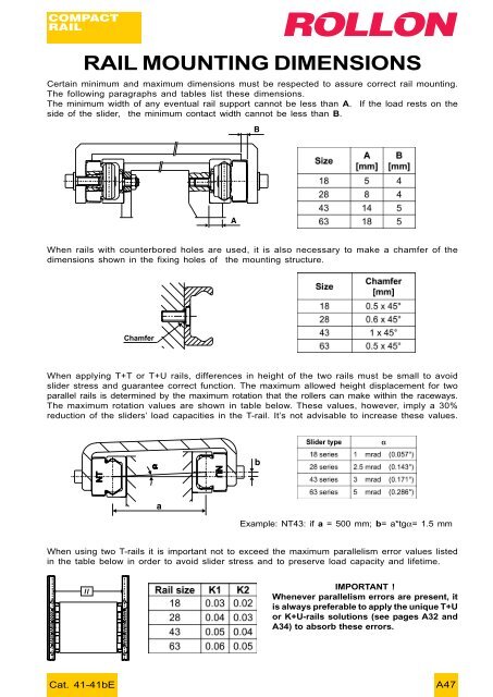
- Page 6 and 7: INDEXRAIL MOUNTING DIMENSIONS......
- Page 9 and 10: SILENT OPERATION LEVELWith today’
- Page 11 and 12: RAILSThree different type rails - e
- Page 13 and 14: SLIDERS- N... SERIES18 SERIESSlider
- Page 15 and 16: SLIDERS- N... SERIES28 SERIESSlider
- Page 17 and 18: RAILS28 SERIESRail weight:1000 g/mH
- Page 19 and 20: SLIDERS- N... SERIES43 SERIESSlider
- Page 21 and 22: RAILS43 SERIESRail weight:2600 g/mW
- Page 23 and 24: 43 SERIESThe sliders of N.43L serie
- Page 25 and 26: RAILS63 SERIESRail weight:6000 g/mW
- Page 27 and 28: CPA / CPN ROLLERSROLLERSThe CPA is
- Page 29 and 30: TORX ® HEAD SCREWSCHARACTERISTICSF
- Page 31 and 32: POSSIBILITIES IN SLIDER MOUNTINGCOM
- Page 37 and 38: In order to obtain the best results
- Page 39 and 40: (5) The lower side of the rail must
- Page 41 and 42: LINEAR PRECISIONRUNNING PARALLELISM
- Page 43 and 44: LIFETIMELIFE CALCULATIONThe dynamic
- Page 45 and 46: - Axial loadNT/CSW18NTE/CSW28NTE/CS
- Page 47: - Axial loadNTE63CSW63- Mx momentNT
- Page 51 and 52: 18 SIZE SLIDERSCoefficient of frict
- Page 53 and 54: - Rail mounting without any support
- Page 55 and 56: MOUNTING OF “T+U” SYSTEMThe mou
- Page 57 and 58: (4) Fix the U.. rail, following the
- Page 59 and 60: VERTICAL MOVEMENTSTATIC VERIFICATIO
- Page 61 and 62: SELECTION FLOW-CHARTThe following f
- Page 63 and 64: EXAMPLES OF APPLICATION3 AXES PALLE
- Page 65 and 66: PLASMA CUTTING MACHINEThis machine
- Page 67 and 68: EXPOSURE UNITIn the photographic ap
- Page 69 and 70: INSERTOUNILINE
- Page 71 and 72: INDEXUNILINE - THE ONLY CHOICE.....
- Page 73 and 74: UNILINE - THE ONLY CHOICEUNILINE is
- Page 75 and 76: “A” FAMILY:Set-screwsMoving tro
- Page 77 and 78: WHICH ACTUATOR TO CHOOSE(PERFORMANC
- Page 79 and 80: A407.5 1542.5 8091.5 165 Stroke91.5
- Page 81 and 82: C55108 200 Stroke108Trolley length(
- Page 83 and 84: A75116 285 Stroke116Trolley length(
- Page 85 and 86: E75116 285 Stroke116* Position of t
- Page 87 and 88: VERSION “L” (Long trolley)“L
- Page 89 and 90: VERSION “H”The H units are “s
- Page 91 and 92: LIFETIMELIFE CALCULATIONThe dynamic
- Page 93 and 94: MOUNTING CONFIGURATIONSAND INSTRUCT
- Page 95 and 96: 2 AXIS GANTRY (Y-2Z and 2Y-Z)In the
- Page 97 and 98: 3 AXIS GANTRY (2X-Y-Z)This example
- Page 99 and 100:
BELT TENSIONINGThe UNILINE linear u
- Page 101 and 102:
MOUNTING ACCESSORIESMETRIC INTERFAC
- Page 103 and 104:
“T” PLATEThis plate allows two
- Page 105 and 106:
OTHER USEFUL INFORMATIONRUNNING PAR
- Page 107 and 108:
The linear slide inside the actuato
- Page 109 and 110:
NotesThe linear actuator is supplie
- Page 111 and 112:
4545Special versionsSpecial version
- Page 113 and 114:
INSERTOTELESCOPIC RAIL
- Page 115 and 116:
INDEXTELESCOPIC RAIL: BEARINGS THAT
- Page 117 and 118:
PRODUCT OVERVIEWAll of the rails in
- Page 119 and 120:
WHAT MAKES ROLLON’S TELESCOPICRAI
- Page 121 and 122:
ELECTROMEDICAL BEDASNLTF44MACHINE T
- Page 123 and 124:
- Single direction stroke (version
- Page 125 and 126:
TECHNICAL DATA:DLCALtotBStrokeTypeL
- Page 127 and 128:
end-stop screwWeight DE22: 2.5 kg/m
- Page 129 and 130:
end-stop screwWeight DBN22: 2.5 kg/
- Page 131 and 132:
ASN SERIESThis slide is formed by a
- Page 133 and 134:
Order code:ASN 63 - 770 - 433Series
- Page 135 and 136:
TECHNICAL DATA:length Lstroke Hleft
- Page 137 and 138:
VERIFICATION OF STATIC LOADAs you c
- Page 139 and 140:
INSERTOEASY RAIL
- Page 141 and 142:
INDEXEASY RAIL: THE SOLUTION IS EAS
- Page 143 and 144:
EXAMPLES OF LOAD CAPACITIES63432211
- Page 145 and 146:
MOUNTING EXAMPLESWith regard to the
- Page 147 and 148:
• “SN35” SERIES15.8M610R2Coun
- Page 149 and 150:
SN63 SERIESSN43 SERIESCat. 41-41bED
- Page 151 and 152:
LIFETIME CALCULATIONThe life of a l
- Page 153 and 154:
INSERTOECOLINE
- Page 155 and 156:
INDEXECOLINE: AFFORDABLE AND INNOVA
- Page 157 and 158:
TECHNICAL DATA AND ORDER CODESRails
- Page 159 and 160:
SETTING SLIDER PRELOAD ANDROLLER OR
- Page 161 and 162:
- “XM37” WITH SINGLE SLIDER “
- Page 163 and 164:
INSERTOX RAIL
- Page 165 and 166:
INDEXTEX - CEX SERIES..............
- Page 167 and 168:
MOUNTED RAIL / SLIDERBeccentric rol
- Page 169 and 170:
ROLLERSCRPACRPNBFG (eccentricity)BD
- Page 171 and 172:
INSERTOCURVILINE
- Page 173 and 174:
INDEXCURVILINE: THE RAIL THAT GOES
- Page 175 and 176:
APPLICATION EXAMPLES:VARIABLE RADIU
- Page 177 and 178:
MOUNTED RAIL / SLIDER(Constant Radi
- Page 179 and 180:
Branches:Via Trieste 26, 20059 Vime