
Create successful ePaper yourself
Turn your PDF publications into a flip-book with our unique Google optimized e-Paper software.
INDEXRAIL MOUNTING DIMENSIONS..............................................................................A47THRUST FORCE.....................................................................................................A48MOUNTING INSTRUCTIONS...................................................................................A50FORMULAE FOR DETERMINING THE LOAD ON THE SLIDER...............................A56SELECTION CRITERIA FOR THE CORRECT COMPACT RAIL SOLUTION..............A58FIELDS APPLICATION............................................................................................A60EXAMPLES OF APPLICATION................................................................................A61ORDER CODES......................................................................................................A66U6 A4Cat. 41-41bE
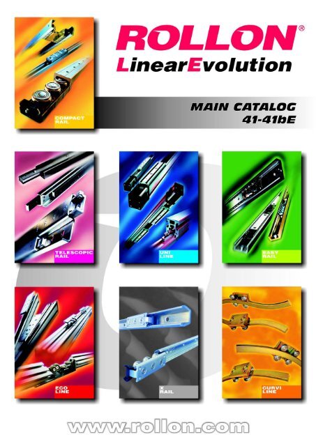
COMPACT RAIL:THE LINEAR MOTION SOLUTIONROLLON’s COMPACT RAIL is different from all other linear bearing systems available in themarket. Compact Rail solves problems.Whereas most linear bearings are descendents of heavy machine tool bearings and thereforeby nature tend to be slow, recirculating-ball carriages mounted on simple round or profiled shafts,ROLLON started from scratch and designed a linear bearing system based on the needs ofmodern design engineers. We realized that while most linear bearings are applied in applicationsrequiring good linear precision, few require machine tool-like, ultra-high precision. High precisiongrade <strong>rail</strong>s (most popular round or profiled shafting fall into this category) are difficult, timeconsuming, and expensive systems that require machining of the mounting surfaces (a costwhich often cannot be passed on to the customer).COMPACT RAIL is a simple, precision, linear bearing system that is easy and inexpensiveto mount to all - even non-machined- surfaces. What’s more, COMPACT RAIL will self-alignto another <strong>rail</strong> if mounting surfaces are not perfectly parallel.We found that many linear bearing applications were in dirty or contaminated environmentsand that engineers were forced to specify external bellows or other costly protective devices.COMPACT RAIL is a well-protected system. The sliders run inside the hardened steel <strong>rail</strong>swhere they are protected. They have spring-loaded wipers which protect the shielded orsealed bearings from debris and damage.Many engineers told us that recirculating ball sliders were slow and noisy and this effectedthe quality of their machines.COMPACT RAIL is a fast (up to 9 m/s) and silent system (much quieter than recirculatingball systems).Our customers told us of their need to make their new machinery as maintenance free aspossible.COMPACT RAIL has “lubed for life” bearings with patented wiper technology that lubricatesthe system as it runs. Even while we have achieved our goals and manufactured the mostcomprehensive linear bearings available, we will continue to strive to build the best productsand surpass the needs of linear motion for the future.“T” RAIL “U” RAIL “K” RAILCat. 41-41bEA5
SILENT OPERATION LEVELWith today’s restrictive regulations for admissible working noise levels, it’s become more andmore important to keep a machine’s operation noise level as low as possible.The COMPACT RAIL system offers very low operation noise level, even when working with highloads and high speed. This is the opposite of recirculating ball sliders that become much noisieras the speed and load increases.Below figure indicates a typical comparison of operation noise level.QUICK AND EASY ASSEMBLYINGThe cost of assembly-time is often neglected during the designing stage as many engineersassume that the time for assembly is a fixed factor, equal for all linear bearings.The COMPACT RAIL system has been studied to facilitate in mounting and to offer high costsavings on assembly-time. In addition, substantial cost savings is also gained due to lowrequirement of the accuracy of the mounting surface finish.The main time saving characteristics are offered by the self-aligning <strong>rail</strong> combinations T/U andK/U, the self-aligning <strong>rail</strong>s with C’sunk fixing holes, and the small number of fixing screws due tothe large pitch of the <strong>rail</strong>s.OPTIMUM PRELOAD SETTINGFor applications where the stiffness or low friction is very critical, the COMPACT RAIL systemoffers the unique possibility of allowing the preload on standard sliders to be set according to theexact needs of the application.All sliders are interchangeable, by just simply resetting the preload.Cat. 41-41bEA7
MAIN COMPONENTSSLIDERS- N... SERIESMaterials:A. Slider body: Aluminium alloy die casting;B. Heads: Polyester,Wipers: Modified Polyamide;C. Caps: Polyester;D. Pins: Steel;E. Rollers: 100Cr6 (52100) Steel;F. Lateral seals: Nytrilic rubber;ACBFDSurface treatment:The slider body is chemical nickel plated.E- C.. SERIESMaterials:A. Slider body: Steel;B. Wipers: Modified Polyamide;C. Pins: Steel;D. Rollers: 100Cr6 (52100) Steel;BACDSurface treatment:The slider body is zinc plated according to ISO 2081.U10 A8Cat. 41-41bE
RAILSThree different type <strong>rail</strong>s - each with a particular raceways shape- are available: T, U and K.T U K- GENERAL CHARACTERISTICSMaterial:Carbon bearing steel;Raceways:Induction hardened;Tolerances:See page A31;Surface treatment:Electrolytic zinc-plating according to ISO 2081 standard (not present on the raceways).See also page A37;- FIXING HOLESThe <strong>rail</strong>s are supplied in two versions, according to the hole type of the fixing screws. C’sunkholes indicated by suffix ..V and counter-bored holes indicated by the suffix ..C. (see page A26for details). I.e. a size 43 T-<strong>rail</strong> with honed raceways and cylindrical fixing holes is indicated bythe code TLC43.- RACEWAYS PRECISION GRADEThe <strong>rail</strong>s are supplied with honed raceways.Cat. 41-41bEA9
GENERAL PERFORMANCELOAD CAPACITIES PER SLIDER- 18 SERIES18Slider typeNo. ofrollersNote: for details about size 18, see page A12C 0 radC 0 axM xM YM z[ N][ N][ Nm][ Nm][Nm]NT183 8202601.5 4.7 8. 2CSW18-603 8202601.5 4.7 8. 2CSW18-804 8203002.8 7.0 24. 7CSW18-1005 9753602.8 9.4 24. 7CSW18-1206 9754403.3 11.8 41. 1- 28 SERIES28Slider typeNo. ofrollersC 0 radC 0 axM xM YM z[ N][ N][ Nm][ Nm][Nm]NTE283 21706406.2 16.0 27. 2NTE28L-5-A5 258090011.5 29.0 81. 7CSW28-80CDW28-803 21706406.2 16.0 27. 2CSW28-1004 217075011.5 21.7 81. 7CSW28-125CDW28-1255 258090011.5 29.0 81. 7CSW28-1506 2580107013.7 36.2 136. 1Note: for details about size 28, see page A16- 43 SERIES43Slider typeNo. ofrollersC 0 radC 0 axM xM YM z[ N][ N][ Nm][ Nm][Nm]NTE433 5500157023.6 60.0 104. 5NTE43L-5-A5 6540221543.6 108.6 313. 5CSW43-120CDW43-1203 5500157023.6 60.0 104. 5CSW43-1504 5500185543.6 81.5 313. 5CSW43-190CDW43-1905 6540221543.6 108.6 313. 5CSW43-2306 6540264552.0 135.8 522. 5Note: for details about size 43, see pages A20 and A21- 63 SERIES63Slider typeNo. ofrollersC 0 radC 0 axM xM YM z[ N][ N][ Nm][ Nm][Nm]NTE633 125006000125271367CSW63-1803 125006000125271367CSW63-2354 1250072002504131100CSW63-2905 1500085002505111100CSW63-3456 15000100003506891830Note: for details about size 63, see page A24M yC 0radC 0axM xMzA10 U12Cat. 41-41bE
SLIDERS- N... SERIES18 SERIESSlider type- CSW.. SERIESNo. ofrollers* For roller characteristics see page A25Type of roller*No. of fixingholesWeight[g]AdjustmentkeyNT18- NU18 3 CPA18- CPN182 30CK18Slider typeCSW18-60-2ZCSW18-60-2RSCSW18-80-2ZCSW18-80-2RSCSW18-100-2ZCSW18-100-2RSCSW18-120-2ZCSW18-120-2RSNo. ofrollersType of roller** For roller characteristics see page A25No. of fixingholesWeight[g]Adjustmentkey3 CPA18- CPN182 40CK184 CPA182 50CK185 CPA184 60CK186 CPA183 70CK18Cat. 41-41bEA11
RAILS18 SERIES Rail weight:550 g/mWith counterbored holesHoles for M4 Torx ®screws suppliedtogether with the <strong>rail</strong>s(see page A27)C’sunk holes for screwsM4x0.7 DIN 7991With countersunk holesRailtypeTLC18 - ULC18TLV18 - ULV18TLC18 ULC18 TLV18 ULV18StandardlengthsL [mm]160 - 240 - 320 - 400 - 480 - 560 - 640 - 720 - 800 - 880 - 9601040 - 1120 - 1200 - 1280 - 1360 - 1440 - 1520 1600 - 16801760 -1840 1920 - 2000*MOUNTED RAIL/SLIDER* Lengths of up to 3760 mmare available upon specialorder. Please consult yournearest branch or distributorfor more informationTL.../NT18 UL.../NU18 TL.../CSW18-T UL.../CSW18-USlider typeC[N]# min. 16.5max. 17.6LOAD CAPACITYThe load capacities indicated in this paragraph,refer to the “standard” positioning of the sliderinto the <strong>rail</strong> with the direction of the fixed rollerscorresponding to that of the radial load.C 0 radC 0 axM xM M z[Nm]Y[ N][ N][ Nm][ Nm]M yC 0radC 0axM x M zsM zdM zdNT1815308202601.5 4.78. 2NU1815308200 0 0 8. 2CSW18-60-..15308202601.5 4.78. 2CSW18-80-..-A15308203002.8 7.0 8.2 24. 7CSW18-80-..-B15308203002.8 7.0 24.7 8. 2CSW18-100-..18309753602.8 9.424. 7CSW18-120-..-A18309754403.3 11.8 24.7 41. 1CSW18-120-..-B18309754403.3 11.8 41.1 24. 7M zs# min. 14.7max. 16.1Note: The load capacities indicated in thetable refer to CSW sliders utilized with T..<strong>rail</strong>s; the values of C 0ax, M xand M yare equalto 0 if used in U-<strong>rail</strong>s.A12 U14Cat. 41-41bE
SLIDERS- N... SERIES28 SERIESSlider typeNo. ofrollers* For roller characteristics see page A25Type of roller*No. of fixingholesWeight[g]AdjustmentkeyNTE28- NUE28 3 CPA28- CPN282 115CK28- N...L SERIESSlider typeNo. ofrollers*Type of roller**No. of fixingholes* The number of rollers varies according to the configuration (see page A16)Weight[g]AdjustmentkeyNTE28L- NUE28L 3 - 5 CPA284 200CK28** For roller characteristics see page A25Cat. 41-41bEA13
- CSW.. SERIES28 SERIESSlider typeCSW28-80-2ZCSW28-80-2RSCSW28-100-2ZCSW28-100-2RSCSW28-125-2ZCSW28-125-2RSCSW28-150-2ZCSW28-150-2RSNo. ofrollersType of roller** For roller characteristics see page A25- CDW.. SERIESNo. of fixingholesWeight[g]Adjustmentkey3 CPA28- CPN282 155CK284 CPA282 195CK285 CPA284 240CK286 CPA283 290CK28Slider typeCDW28-80-2ZCDW28-80-2RSCDW28-125-2ZCDW28-125-2RSNo. ofrollersType of roller** For roller characteristics see page A25No. of fixingholesWeight[g]Adjustmentkey3 CPA282 215CK285 CPA284 300CK28A14 U16Cat. 41-41bE
RAILS28 SERIESRail weight:1000 g/mHoles for M5 Torx ® screwssupplied together with the<strong>rail</strong>s (see page A27)With counterbored holesC’sunk holes for screwsM5x0.8 DIN 7991With countersunk holesTLC28 ULC28 TLV28 ULV28RailtypeTLC28 - ULC28TLV28 - ULV28StandardlengthsL [mm]240 - 320 - 400 - 480 - 560 - 640 - 720 - 800 - 880 - 960 - 10401120 - 1200 - 1280 - 1360 - 1440 - 1520 - 1600 - 1680 - 1760 - 18401920 - 2000 - 2080 - 2160 - 2240 - 2320 - 2400 - 2480 - 25602640 - 2720 - 2800 - 2880 - 2960 - 3040 - 3120 - 3200 - 3280 - 33603440 - 3520 - 3600 - 3680 - 3760 - 3840 - 3920 - 4000 - 4080MOUNTED RAIL/SLIDERTL.../NTE28TL.../NTE28LUL.../NUE28UL.../NUE28LTL.../CSW28-TUL.../CSW28-U# min. 24max. 25.3TL.../CDW28-TUL.../CDW28-U# min. 23.3max. 25.2# min. 23.5max. 25.4Cat. 41-41bEA15
LOAD CAPACITYThe load capacities indicated in this paragraph,refer to the “standard” positioning of the slider intothe <strong>rail</strong> with the direction of the fixed rollerscorresponding to that of the radial load.M yC 0radC 0axM x M zsM zdSlider typeC[N]NTE28L-3-A / NUE28L-3-AC 0 radC 0 axM xM M z[Nm]Y[ N][ N][ Nm][ Nm]M zdNTE28426021706406.2 16.027. 2NUE28426021700 0 0 27. 2CSW28-80-..426021706406.2 16.027. 2CSW28-100-..-A4260217075011.5 21.7 27.2 81. 7CSW28-100-..-B4260217075011.5 21.7 81.7 27. 2CSW28-125-..5065258090011.5 29.081. 7CSW28-150-..-A50652580107013.7 36.2 81.7 136. 1CSW28-150-..-B50652580107013.7 36.2 136.1 81. 7CDW28-80-..426021706406.2 16.027. 2CDW28-125-..5065258090011.5 29.081. 7Note: The load capacities indicated in the table refer to CSW and CDW sliders utilized with T.. <strong>rail</strong>s;the values of C oax, M xand M yare equal to 0 if used in U-<strong>rail</strong>s.The sliders of N.28L series are available in six configurations studied to offer great versatility of use.Slider typeC[N]C 0 radC 0 axM xM M z[Nm]Y[ N][ N][ Nm][ Nm]M zdNTE28L-3-A426021706406.2 29.054. 4NTE28L-4-A4260217075011.5 29.0 54.4 108. 5NTE28L-4-B4260217075011.5 29.0 108.5 54. 4NTE28L-4-C4260217075011.5 29.081. 7NTE28L-5-A5065258090011.5 29.081. 7NTE28L-5-B681634726406.2 29.054. 4NUE28L-3-A426021700 0 0 54. 4NUE28L-4-A426021700 0 0 54.4 108. 5NUE28L-4-B426021700 0 0 108.5 54. 4NUE28L-4-C426021700 0 0 81. 7NUE28L-5-A506525800 0 0 81. 7NUE28L-5-B681634720 0 0 54. 4M zsM zsSLIDER CONFIGURATIONSNTE28L-4-C / NUE28L-4-CNTE28L-4-A / NUE28L-4-ANTE28L-5-A / NUE28L-5-ANTE28L-4-B / NUE28L-4-BNTE28L-5-B / NUE28L-5-BA16 U18Cat. 41-41bE
SLIDERS- N... SERIES43 SERIESSlider type- N...L SERIESNo. ofrollers* For roller characteristics see page A25Type of roller*No. of fixingholesWeight[g]AdjustmentkeyNTE43- NUE43 3 CPA43- CPN432 385CK43NKE433 CRA43- CRN432 385CK43Slider typeNo. ofrollers*Type of roller**No. of fixingholesWeight[g]AdjustmentkeyNTE43L- NUE43L 3 - 5 CPA434 600CK43NKE43L3 - 5 CRA434 600CK43* The number of rollers varies according to the configuration (see page A21)** For roller characteristics see page A25Cat. 41-41bEA17
- CSW.. SERIES43 SERIESSlider typeCSW43-120-2ZCSW43-120-2RSCSW43-150-2ZCSW43-150-2RSCSW43-190-2ZCSW43-190-2RSCSW43-230-2ZCSW43-230-2RSNo. ofrollersType of roller** For roller characteristics see page A25- CDW.. SERIESNo. of fixingholesWeight[g]Adjustmentkey3 CPA43-CPN432 530CK434 CPA432 680CK435 CPA434 840CK436 CPA433 1010CK43Slider typeCDW43-120-2ZCDW43-120-2RSCDW43-190-2ZCDW43-190-2RSNo. ofrollersType of roller** For roller characteristics see page A25No. of fixingholesWeight[g]Adjustmentkey3 CPA432 640CK435 CPA434 950CK43A18 U20Cat. 41-41bE
RAILS43 SERIESRail weight:2600 g/mWith counterbored holesHoles for M8 Torx ®screws suppliedtogether with the <strong>rail</strong>s(see page A27)With countersunk holesTLC43 ULC43 KLC43C’sunk holes for screwsM8x1.25 DIN 7991TLV43 ULV43 KLV43RailtypeTLC43 - TLV43ULC43 - ULV43KLC43 - KLV43StandardlengthsL [mm]400 - 480 - 560 - 640 - 720 - 800 - 880 - 960 - 1040 - 1120 - 12001280 - 1360 - 1440 - 1520 - 1600 - 1680 - 1760 - 1840 - 19202000 - 2080 - 2160 - 2240 - 2320 - 2400 - 2480 - 2560 - 26402720 - 2800 - 2880 - 2960 - 3040 - 3120 - 3200 - 3280 - 33603440 - 3520 - 3600 - 3680 - 3760 - 3840 - 3920 - 4000 - 4080Cat. 41-41bEA19
TL.../NTE43TL.../NTE43LUL.../NUE43UL.../NUE43L43 SERIESMOUNTED RAIL/SLIDERKL.../NKE43KL.../NKE43LTL.../CSW43-TUL.../CSW43-UTL.../CDW43-T# min. 37max. 39.5UL.../CDW43-U# min. 35.6max. 39.5* The K-<strong>rail</strong> allows the K-slider to rotate, thereforethis dimension will change under rotation.For more details see page A34.The K-<strong>rail</strong> must be mounted in such a way thatthe radial load is always carried by the rollers onthe slider in contact with the “V” shaped raceway.# min. 35.9max. 39.8LOAD CAPACITYThe load capacities indicated in this paragraph, refer to the “standard” positioning of the sliderinto the <strong>rail</strong> with the direction of the fixed rollers corresponding to that of the radial load.C 0radM yM x M zsM zdC 0axSlider typeC[N]C 0 radC 0 axM xM M z[Nm]Y[ N][ N][ Nm][ Nm]NTE43122805500157023.6 60.0104. 5NUE431228055000 0 0 104. 5NKE4312280510013200 50.496. 9CSW43-120-..122805500157023.6 60.0104. 5CSW43-150-..-A122805500185543.6 81.5 104.5 313. 5CSW43-150-..-B122805500185543.6 81.5 313.5 104. 5CSW43-190-..146756540221543.6 108.6 313. 5CSW43-230-..-A146756540221552.0 135.8 313.5 522. 5CSW43-230-..-B146756540221552.0 135.8 522.5 313. 5CDW43-120-..122805500157023.6 60.0104. 5CDW43-190-..146756540221543.6 108.6 313. 5Note: The load capacities indicated in the table refer to CSW and CDW sliders utilized with T.. <strong>rail</strong>s; thevalues of C 0ax, M xand M yare equal to 0 if used in U-<strong>rail</strong>s.M zdM zsA20 U22Cat. 41-41bE
43 SERIESThe sliders of N.43L series are available in six configurations studied to offer great versatility of use.Slider typeC[N]C 0 radC 0 axM xM M z[Nm]Y[ N][ N][ Nm][ Nm]NTE43L-3-A122805500157023.6 108.6209NTE43L-4-A122805500185543.6 108.6 209418NTE43L-4-B122805500185543.6 108.6 418209NTE43L-4-C122805500185543.6 108.6 313. 5NTE43L-5-A146756540221543.6 108.6 313. 5NTE43L-5-B196508800157023.6 108.6209NUE43L-3-A1228055000 0 0 209NUE43L-4-A1228055000 0 0 209418NUE43L-4-B1228055000 0 0 418209NUE43L-4-C1228055000 0 0 313. 5NUE43L-5-A1467565400 0 0 313. 5NUE43L-5-B1965088000 0 0 209NKE43L-3-A12280510013200 97.7188. 7NK43L-4-A12280510013200 97.7 188.7 377. 3NKE43L-4-B12280510013200 97.7 377.3 188. 7NKE43L-4-C12280510013200 97.7283NKE43L-5-A14675606519800 97.7283NKE43L-5-B19650816013200 97.7188. 7M zdM zsSLIDER CONFIGURATIONSNTE43L-3-A / NUE43L-3-A / NKE43L-3-ANTE43L-4-C / NUE43L-4-C / NKE43L-4-CNTE43L-4-A / NUE43L-4-A / NKE43L-4-ANTE43L-5-A / NUE43L-5-A / NKE43L-5-ANTE43L-4-B / NUE43L-4-B / NKE43L-4-BNTE43L-5-B / NUE43L-5-B / NKE43L-5-BCat. 41-41bEA21
SLIDERS- N... SERIES63 SERIESSlider type- CSW.. SERIESNo. ofrollersType of roller*No. of fixingholesWeight[g]AdjustmentkeyNTE63- NUE63 3 CPA43- CPN634 1070CK63NKE633 CRA63- CRN634 1070CK63* For roller characteristics see page A25Slider typeNo. ofrollersType of roller*No. of fixingholesWeight[g]AdjustmentkeyCSW63-180-2ZR3 CPA634 1660CK63CSW63-235-2ZR4 CPA635 2170CK63CSW63-290-2ZR5 CPA636 2670CK63CSW63-345-2ZR6 CPA637 3170CK63* For roller characteristics see page A25A22 U24Cat. 41-41bE
RAILS63 SERIESRail weight:6000 g/mWith counterbored holesHoles for M8 “Torx ® screws”supplied together with the <strong>rail</strong>s(see page A27)With countersunk holesC’sunk holes for screwsM10x1.5 DIN 7991TLC63 ULC63 KLC63TLV63 ULV63 KLV63RailtypeTLC63 - TLV63ULC63 - ULV63KLC63 - KLV63StandardlengthsL [mm]560 - 640 - 720 - 800 - 880 - 960 - 1040 - 1120 - 1200 - 1280 - 13601440 - 1520 - 1600 - 1680 - 1760 1840 - 1920 - 2000 - 2080 - 21602240 - 2320 - 2400 - 2480 - 2560 - 2640 - 2720 - 2800 - 2880 - 29603040 - 3120 - 3200 - 3280 - 3360 - 3440 - 3520 - 3600 - 3680 - 37603840 - 3920 - 4000 - 4080Cat. 41-41bEA23
TL.../NTE63UL.../NUE6363 SERIESMOUNTED RAIL/SLIDERKL.../NKE63TL.../CSW63-T# min. 50.5max. 54UL.../CSW63-U* The K-<strong>rail</strong> allows the K-slider to rotate,therefore this dimension will change underrotation. For more details see page A34.The K-<strong>rail</strong> must be mounted in such a waythat the radial load is always carried by therollers on the slider in contact with the “V”shaped raceway.# min. 49.4max. 53.3LOAD CAPACITYThe load capacities indicated in this paragraph, refer to the “standard” positioning of the sliderinto the <strong>rail</strong> with the direction of the fixed rollers (concentric) corresponding to that of the radialload.C 0radM yM x M zsM zdC 0axSlider typeC[N]C 0 radC 0 axM xM M z[Nm]Y[ N][ N][ Nm][ Nm]NTE6330750125006000125271367NUE6330750125000 0 0 367NKE63307501155050450 235335CSW63-180-..30750125006000125271367CSW63-235-..-A307501250072002504133671100CSW63-235-..-B307501250072002504131100367CSW63-290-..366001500085002505111100CSW63-345-..-A36600150001000035068911001830CSW63-345-..-B36600150001000035068918301100Note: The load capacities indicated in the table refer to CSW sliders utilized with T.. <strong>rail</strong>s; ihe values of C 0ax,M xand M yare equal to 0 if used with U-<strong>rail</strong>s.M zdM zsA24 U26Cat. 41-41bE
CPA / CPN ROLLERSROLLERSThe CPA is the eccentric roller used for the preload settingwhile the CPN is the concentric roller. Both the CPN and theCPA rollers are designed for T and U <strong>rail</strong>s.The internal thread of the pivot has a special antilooseningshape, suitable for standard screws.TypeCPA18-2ZCPA18-2RSCPA28-2ZCPA28-2RSCPA43-2ZCPA43-2RSD imensions [ mm]C[N]A B F G D M H eC 0 radWeight[ N][g]144 1.551.8 6 M45.5 0.4 765410423.27 2.2 3.8 10M57 0.6 213010851935112.5 4.5 12M6120.8 6140275060CPA63-2ZR5017.5 2.3 6 18M10161.2 153756250190CPN18-2ZCPN18-2RSCPN28-2ZCPN28-2RSCPN43-2ZCPN43-2RS144 1.551.8 6 M45.5 - 765410423.27 2.2 3.8 10M57 - 213010851935112.5 4.5 12M612- 6140275060CPN63-2ZR5017.5 2.3 6 18M816- 153756250190CRA / CRN ROLLERSThe CRA is the eccentric roller used for the preload settingwhile the CRN is the concentric roller. Both the CRA and theCPN rollers are designed for K <strong>rail</strong>s.The internal thread of the pivot has a special antilooseningshape, suitable for standard screws.TypeD imensions [ mm]C[N]A B F G D M H eC 0 radWeight[ N][g]CRA43-2Z35.6 112.5 4.5 12M6120.8 6140255060CRA63-2ZR49.7 17.5 2.3 6 18M10161.2 153755775190CRN43-2Z35.6 112.5 4.5 12M612- 6140255060CRN63-2ZR49.7 17.5 2.3 6 18M816- 153755775190SPECIAL SLIDERSBy utilizing the rollers shown above, ROLLON can supply special CSW sliders with lengths,holes, and roller positions different from the standard versions.Contact our Technical Department for more information.Cat. 41-41bEA25
RAIL MOUNTING-HOLE CRITERIAROLLON offers two <strong>rail</strong> mounting hole systems for the COMPACT RAIL system:counterbored and countersunksunk.In the two paragraphs below the criteria for which system should be selected is explained.COMPACT “C” - Rails with counterbored holesThere are two main reasons for choosing counterbored mounting holes.1) High linear precision, which implies precise <strong>rail</strong> mounting, can only be offered by counterboredfixing holes. Counterbored fixing holes allow precise <strong>rail</strong> positioning according to an externalreference which assures and controls the required precision tolerances.2) The need to mount a <strong>rail</strong> using fixing holes which are not aligned is a common situation whenhaving only one <strong>rail</strong> and low precision requirements. In this case the counterbored holes areneeded because, having a larger diameter when compared to the screws, they allow the <strong>rail</strong> toadjust slightly during mounting.COMPACT “V” - Rails with countersunk holesSelection of <strong>rail</strong>s with c’sunk holes is often based on the application’s low requirement for linearprecision and the decent alignment of the fixing holes. The use of countersunk fixing holeseliminates the necessity of time consuming <strong>rail</strong> reference positioning, as the <strong>rail</strong> aligns itselfaccording to the average hole position. The use of countersunksunk mounting holes could beused in many handling or automation applications or most applications where the <strong>rail</strong> is mountedto a T-slot.A26 U28Cat. 41-41bE
TORX ® HEAD SCREWSCHARACTERISTICSFor the COMPACT RAIL counterbored hole <strong>rail</strong>s,special dimension screws have been designed withTORX ® fixing housing.The TORX ® socket shallow head screws guaranteehigh tightening torque without plastic deformation orcracks. This increased torque allows the <strong>rail</strong>s toremain well fixed even in the presence of vibrations.Tightening torque is transmitted with safety becausethe guide angle of 15° is very similar to the optimalvalue of torque transmission of gears. The largecontact area - even with a reduced depth - eliminatesany chance of concentrated stress and deformations,with consequent reduction of the wear of housing andkey, minimalizing the risk of the key sliding and“stripping” the housing.The six vertical contact surfaces maintain the key inthe right position, avoiding damage and workingwithout peak loads.very smallcontact arealarge contactareahigh specificpressureHEXAGONALHOUSINGlow specificpressureTORX ®HOUSINGTECHNICAL DATANote: all <strong>rail</strong>s with counterbored fixing holeswill be supplied with these TORX ® screws.Extra TORX ® screws and inserts can beordered. See table at right.Cat. 41-41bEA27
GENERAL INSTRUCTIONS FOR THEUSE OF SLIDERSPOSITION OF THE ROLLERSThe sliders NTE, NUE and NKE are equippedwith rollers which are alternately in contact withthe two raceways.A triangular symbol* engraved on the plasticcaps covering the pivots, identifies theircontact side on the <strong>rail</strong>.The sliders CSW and CDW are equipped withthree, four, five or six rollers, arranged asfollows (as shown in the figure, the fixed rollersare identified by a “o” symbol stamped on thebar in connection with the fixed rollers):*IMPORTANT !Check that the direction of the rollerscorresponds to that of the external loads.PRELOADING THE SLIDERSCorrect preload setting is very important to the quality of movement and to the lifetime of thesystem. Normally the sliders are supplied mounted and preloaded in the <strong>rail</strong>s. When suppliedseparately, the preload must be set by the user. This simple operation must also be carried out ifthe slider is removed from one <strong>rail</strong> and mounted in another.PRELOAD SETTING PROCEDURE:(1) Assure that the raceways are clean.(2) Insert the slider into the <strong>rail</strong>. CSW and CDW sliders must be inserted without wipers. Slightlyloosen only fixing screws of the rollers to be set.(3) Position the slider at one end of the <strong>rail</strong>.(4) For the U-<strong>rail</strong>s a thin, strong support (i.e preload key) must be inserted under the ends ofslider body to maintain the slider horizontal in the flat raceways.(5) Insert the special flat preload key between the <strong>rail</strong> and slider on the side with the triangularsymbol (NTE, NUE, NKE), triangular symbol associated to a red screw’s head (NTE..L, NUE..L,NKE..L) or circular symbol (CSW, CDW).(6) Carefully turn the preload key clockwise until the eccentric roller is in contact with the upperraceway and until any clearance is eliminated. Only a small preload is needed. High preloadsetting increases friction which reduces the lifetime.(7) While holding the position of the rollers firm with the preload key, carefully tighten the fixingscrew. The correct tightening torque of the screws will be applied later. See (10) and drawingbelow.(8) Move the slider along the <strong>rail</strong> to verify the preload setting. The movement should be smoothand at no point of the <strong>rail</strong> should the slider have any clearance.(9) For sliders with more than 3 rollers, repeat this procedure for each eccentric roller. Start preloadsetting with the first roller after the one indicated with red paint. Make sure that all rollers havethe correct contact with the raceways.(10) Using the correct tighteningvalues, tighten all fixing screws.Make sure to block the roller withthe preload key while doing this. Aspecial locking thread inside thepivot guarantees that the roller willremain in the set position.(11) Mount then the CSW andCDW’s wipers and check thatraceways are correctly lubricated.A28 U30Cat. 41-41bE
POSSIBILITIES IN SLIDER MOUNTINGCOMPACT RAIL sliders offer a complete rangeof fixing possibilities. In fact, NTE, NUE, NKEand CSW sliders give the possibility to fix themoving element to the lateral side. In addition,N. 63 can be fixed from behind. CDW slidershave wider body to allow for top or bottom sidemounting.SLIDERS UNDER YAWING MOMENTFor applications where an overhanging load acts on a single slider in one <strong>rail</strong>, and therebycreates a yawing moment (Mz) in one direction, the COMPACT RAIL system offers sliders with 4or 6 rollers in different configurations, each one determined by the roller position available in twoconfigurations, “A” or “B”, determined by the roller positions. The Mz moment capacity of thesesliders changes significantly according to the direction of the moment: clockwise orcounterclockwise. Therefore it is very important to choose the correct combination of sliderconfiguration in a pair of <strong>rail</strong>s when a higher Mz moment is required. Since 3 and 5 rollers slidersare symmetrical, the Mz moment is the same in both directions.CSW with 4 rollersconfiguration AandN...L-4-ACSW with 4 rollersconfiguration BandN...L-4-BSLIDERS UNDER OVERHANGING LOADFor applications where an overhanging load is supported by two sliders in the same <strong>rail</strong> creatingan overhanging load in one direction and consequently an opposite load reaction on each ofthe sliders, it is important to ensure that the correct configurations of the slider are properlypositioned. This means that when using: NTE, NUE and CSW sliders with 3 and 5 rollers, one ofthe sliders has to be mounted inverted so that the slider is loaded on the side with most rollers(this is not possible with NKE sliders, due to different raceway shape). CSW sliders with 4 or 6rollers and the same radial load capacity are mounted with the same load direction. The topmounting CDW sliders cannot be inverted due to the positioning of the rollers in respect to thetop of the <strong>rail</strong> and are therefore offered in “A” and “B” configurations. See figure below.CDW with 5 rollersconfiguration AWORKING TEMPERATURECDW with 5 rollersconfiguration BThe continuous working temperature range is -30°C/+120°C (-22°F/+248°F), with peaks of 150°C(302°F). Higher peak temperatures (160°C/+170°C) (+320°F/+338°F) can be reached by C..seriessliders (sizes 18, 28, 43 only), by dismounting the wipers.Cat. 41-41bEA29
GENERAL TOLERANCESRAIL TOLERANCESL - Dimensional Tolerance on lengthE - True-position Tolerance:the tolerance area is limited from a circle of Ediameter, whose center is in the exact theoreticalcenter of the considered point.- Notes for <strong>rail</strong> mounting with counterbored fixing screws:As indicated on page A26, the c’sunk screw head fits into the countersink and does not permitany adjustment of the <strong>rail</strong>. The counterbored hole in the <strong>rail</strong> permits the counterbored fixingscrew head a certain degree of displacement for optimal <strong>rail</strong> positioning as shown in the figurebelow.T areaMinimum diameter of<strong>rail</strong> fixing holeScrew diameterT area - is the diameter of the displacement area thatthe screw center can be moved within, while stillassuring correct alignment.IMPORTANT !Due to the design of our counterbored screws and holes in the <strong>rail</strong>s, it is necessary to chamferthe mounting holes of the mounting structure. For more details see page A47.A30 U32Cat. 41-41bE
In order to obtain the best results with K+Usystem, it’s advisable to utilize NUE.. slidersin the U-<strong>rail</strong>s.All the following data about U-<strong>rail</strong>s refer to thissolution.It’s important to consider that during themovement, while the slider in the K-<strong>rail</strong> rotates,the slider in the U-<strong>rail</strong> rotates and offers an axialdisplacement. The combination of thesecorrective movements must not exceed themaximum values listed below.Considering the NUE.. slider competely rotatedat its maximum value (2° for 43 size and 1° for63), the maximum and minimum axialpositioning are identified by the values of B 0maxand B 0min, which already take into considerationthe axial displacement due to the rotation. B 0nomis the suggested value for the “nominal”starting position of NUE.. slider in the U-<strong>rail</strong>, tobe utilized for the K+U system:The K+U system can be used in differentconfigurations.Considering the same example made in theprevious chapter, this solution, besides toavoid oscillations an consequent overturningmoments, allows to absorb large errors ofvertical parallelism between the <strong>rail</strong>s, withoutcompromising the sliding quality. This is veryimportant because of the difficulties toguarantee good values of vertical parallelism,especially when the distance between the <strong>rail</strong>sis very great.KUCat. 41-41bEA35
JOINED RAILSGENERAL INFORMATIONSThe maximum lengths of track-<strong>rail</strong>s in one single piece are given on pages A12, A15, A19 andA23. Joined <strong>rail</strong>s obtained by connecting two or more <strong>rail</strong>s can be ordered. Joined <strong>rail</strong>s aresquared, marked, and supplied with additional mounting holes on the ends of the <strong>rail</strong>s to beconnected. The <strong>rail</strong>s are supplied with the two supplementary screws which, providing that thisdescription of the procedure is followed, enable the slider to run smoothly over the joint.Extra threaded holes have to be drilled in the element supporting the <strong>rail</strong> according to the table.The end-screws for all types are supplied with the joined <strong>rail</strong>s and they consist of the samescrews utilized for the fixing of <strong>rail</strong>s with counterbored holes (see page A27).The alignment device can be ordered with the code indicated in table.DIRECTION FOR THE ASSEMBLY OF JOINED RAILSOnce holes for screws are drilled in a straightline on the supporting element, joined <strong>rail</strong>smust be assembled by following thisprocedure:(1) Fix the pieces of the <strong>rail</strong> to the supportingelement by tightening all the fixing screwsexcept the ones close to the end to be joined(do not set the <strong>rail</strong>s on a fixed externalreference plane as you must align theinternal raceways first);(2) Insert the special end screws, withouttightening (see Fig. A);Fig. A(3) Place the alignment device on the jointand tighten uniformly both expandingscrewsuntil alignment the raceways isobtained (see Fig.B);Fig. B(4) After step (3), the bases of the two <strong>rail</strong>smay not be coplanar and there may be a gapbetween <strong>rail</strong> and fixing surface. In this casethe support of the ends of the <strong>rail</strong>s must beassured by inserting shims in the gaps;A36 U38Cat. 41-41bE
(5) The lower side of the <strong>rail</strong> must be supportedalong the joint. If this side also appears to bemisaligned then shims have to be used herealso in order to give correct support to theends (see Fig. C);(6) Tighten thoroughly the special end screwsby inserting the key through the holes of thealignment device (see Fig. D);Fig. C(7) For c’sunk fixing holes, first tighten thescrews close to the joined ends then thescrews moving towards the center of the <strong>rail</strong>.For counterbored fixing holes, first adjust the<strong>rail</strong> in accordance to the reference side (seepage A50), then follow the same procedure;Fig. D(8) Remove the device.PROTECTION SYSTEMSANTICORROSION PROTECTIONThe <strong>rail</strong>s are protected against corrosion through electrolytic zinc-plating, according to ISO 2081standards. The honing of raceways of all <strong>rail</strong>s eliminates the zinc-plating on these surfaces.The raceways are protected by a film of grease.If the application requires linear bearings with a greater degree of protection, it is possible toorder them with chemical nickel plating.In such cases the nickel plating is present on the whole <strong>rail</strong> surface.PROTECTION AGAINST IMPURITIESThe life calculation (see page A41) presumes that the working environment of the linear bearingis clean. In order to achieve clean working conditions, the sliders are equipped with adequateprotection system. NTE, NUE, NKE are equipped with a protection systems composed of lateralseals and strong spring loaded wipers in both heads, for automatically cleaning the raceways.The slider heads can be changed for replacement, or in order to make the same slider utilizableon both T and U <strong>rail</strong>s ,while NKE sliders can only be used with K-<strong>rail</strong>s. In these cases, except forNT18 and NU18, which have snap on heads without grease-nipples, it’s necessary to loosen thegrease-nipple, mount the new heads and re-tighten the grease-nipples using the following torquevalues:CSW and CDW are equipped with strong and flexible wipers which clean the raceways.Cat. 41-41bEA37
PRELOADCLASSES OF PRELOADThe sliders which are adjusted and mountedin the <strong>rail</strong>s at our factory are available in twopreload classes:- K1 standard preload, corresponds to a slider/<strong>rail</strong> combination without clearance or with aminimum preload, in order to obtain thesmoothest run;- K2 medium preload, corresponds to a slider/<strong>rail</strong> combination with preload, in order toincrease the stiffness (see from page A42 toA45).When sliders with K2 preload are used, areduction of load capacity and life must betaken into consideration according to thefollowing table:“y” coefficient has to be used in expression (1)on page A40 (verification under static load).If the setting is made by the user or in case itshould be modified from the original setting, thepreload can either estimated empirically or bysetting the slider outside the <strong>rail</strong> and measuringthe interference that is the distance across thecontact lines of the rollers minus the distancebetween the raceways (see table below).* measured at the point of maximum distance between theraceways.The precise adjustment of the slider preload outside the <strong>rail</strong> requires a special device, availableupon request. Remember that the preload influences the life of linear bearing (see page A41).EXTERNAL PRELOADThe unique construction of the ROLLONlinear bearing also permits preloading of theslider from the outside at selected point alongthe length of the <strong>rail</strong>.Preload can be obtained by compressing theflanges of the <strong>rail</strong> as indicated in the picturein this page.This “local” preload enables higher stiffnessto be obtained only at the points of the <strong>rail</strong>where it’s necessary (for example at thereversing points where higher dynamics loadoccur). This selective preload may increasesthe life of the linear bearing by avoiding thenecessity to have a constant higher preloadapplied over the whole length of the <strong>rail</strong>.Furthermore the force required to move theslider is reduced at those points where ahigher preload is not necessary.It is possible to check the value of externallyapplied preload through two gauges whichmeasure the deformation of the <strong>rail</strong> flanges.These are deformed by a pressure devicewhich acts on them (see drawing at thebottom right).The operation must be made after removingthe slider from the area to be preloaded.From the diagram below, it is possible to obtainthe value of the equivalent load as a function ofthe total deformation of the two flanges.All figures refer to sliders with three rollers.Equivalent load [ % C 0rad]δ [µm]A38 U40Cat. 41-41bE
LINEAR PRECISIONRUNNING PARALLELISMThe precision of the COMPACT RAIL system is determined by the precision of the raceways.Linear precision means the running parallelism of the slider i.e. the maximum deviation of theslider referred to the lateral surface and to the supporting one, during it’s run along the <strong>rail</strong>.The values indicated refer to a <strong>rail</strong> properly mounted to a rigid surface using all the mountingholes. While the <strong>rail</strong> may not seem straight before mounting this will not effect the precision.µmµmLength [mm]Length [mm]Variation of the dimensions between two 3 roller slider in the same <strong>rail</strong>:Cat. 41-41bEA39
VERIFICATION UNDER STATIC LOADCALCULATIONThe values of static load rating given on pages A12, A16, A20, A21 and A24 for each slider,represent the maximum allowable loads, above which a permanent deformation of the racewayscould occur and consequently the running quality could be compromised.The verification is made:- by calculating the forces and the moments acting simultaneously on each slider- by comparing these values with the corresponding load ratings.If:P r, P aare the radial and axial resultants of the external forces, in N;M 1, M 2, M 3are the external moments, in Nm;C 0rad, C 0ax,M x, M y, M zare the load ratings in the various directions, given on pages A12, A16, A20,A21 and A24;z is the security factor (see relative table),the result should be:Security factor z:The safety factor z should be lowest when the dynamic forces to be added to the loads can bedetermined accurately, and higher when overloads may occur, especially dynamic loads suchas shocks and vibrations.Please contact our Application Engineering Department if further information is required.If two or more of the described loads act together, the result should be:[1]If the slider is preloaded, when:the value of y (see the table) should be added in formula [1].A40 U42Cat. 41-41bE
LIFETIMELIFE CALCULATIONThe dynamic load rating C is a conventional load rating used in life calculations. The life towhich this load rating is related is 100 km.The values of C are given for the different series of sliders on pages A12, A16, A20, A21 andA24. Life, load rating and equivalent external load are related to each other by the formula:where:L kmis the theoretical life in km;C is the dynamic load rating in Newton;P is the equivalent external load in Newton;f cis the contact factor;f iis the service factor;f his the stroke factor;The equivalent external load P is the load whose effect is equivalent to the sum of the effects ofthe forces and moments acting simultaneously on the slider. Knowing the various loadcomponents acting on the slider (see page A40), the value of P can be calculated according tothe expression:In the above expression the loads are considered as constant in time. Instantaneous forces notexceeding maximum capacities, do not influence the life and can therefore be disregarded.The factor f crefers to applications where more than one slider pass over the same point in the<strong>rail</strong>, i.e. when the sliders do not pass the same point no reduction factor shall be used. The f cfactor has the following values:The service factor f ihas a similar meaning to that of the safety factor z in the verification understatic load, and is equal to:The stroke factor f htakes account of the fact thatthe raceways are stressed more frequently whenthe slider runs short strokes, with equal total run.The graph gives the values of f h(with strokeslonger than 1 m, f hremains equal to 1):f hStroke [m]Cat. 41-41bEA41
STIFFNESSTOTAL DEFORMATIONThe total deformation of the linear bearing under loads P or Moments M (M Xapplied on oneslider only) is indicated below.As shown in the graphs, the stiffness of the slide can be increased by supporting the flanges ofthe <strong>rail</strong>. The values given in the diagrams refer only to the deformation of the linear bearing,while the structure to which the linear bearing is fixed is considered non-deformable.18, 28, 43 SERIESThe deformations given in the diagrams refer to sliders with three rollers and K1 preload.These values are reduced by 25% in case of K2 preload.- Radial loadNT/NU/CSW18NTE/NUE/CSW28NTE/NUE/CSW43Not supported flangeNT/NU/CSW18NTE/NUE/CSW28NTE/NUE/CSW43Supported flangeA42 U44Cat. 41-41bE
- Axial loadNT/CSW18NTE/CSW28NTE/CSW43- Mx momentNT/CSW18NTE/CSW28NTE/CSW43When the slider supports a momentMx, higher stiffness is obtained byplacing the slider with the rollerspositioned as indicated in the picture.The diagrams refer to this orientation.Cat. 41-41bEA43
63 SERIESThe deformations given in the diagrams refer to sliders with three rollers and K1 preload.These values are reduced by 25% in case of K2 preload.- Radial loadNTE/NUE63CSW63Not supported flangeNTE/NUE63CSW63Supported flangeA44 U46Cat. 41-41bE
- Axial loadNTE63CSW63- Mx momentNTE63CSW63When the slider supports a momentMx, higher stiffness is obtained byplacing the slider with the rollerspositioned as indicated in the picture.The diagrams refer to this orientation.Cat. 41-41bEA45
LUBRICATIONROLLER LUBRICATIONThe rollers are lubricated for life.RACEWAY LUBRICATIONIt is necessary to have a thin film of lubrication that does not allow direct contact of the rollers andthe raceway surfaces. The use of a lubricating grease during normal operation:- minimalizes reduces the friction;- reduces the wear;- reduces the stress on the contact surfaces caused by elastic deformations.- Allows the achieving of the life indicated on page A41.- Contributes to the protection of metal surfaces against corrosion.- Maintenance free auto lubrication systemWith the standard heads available for N series sliders of the 28, 43, and 63 sizes, it is possible toeliminate periodic lubrication maintenance. The heads have a strong felt-like material loadedwith liquid grease that is gradually released during the constant contact with the races. Thesewipers last 2 millions cycles (for the slider lifetime see page A41). Through the grease nipples(see below), it is possible to reload the wipers with a liquid grease (characteristics below).order code:NTE43 L - 3 - Aslider type(NTE, NUE, NKE)dimension(28, 43, 63)long slider versionnumber of rollers(3, 4, 5)configuration(A, B, C)Head order code:W NTE 43- Periodic lubricationheadslider type(NTE, NUE, NKE)dimension(28, 43, 63)The lubrication interval depends on many factors, such as working conditions, speed andtemperature. As a guideline, lubrication every 50,000 cycles, or every six months, is recommended.NTE, NUE and NKE sliders (except the type NT / NU18) are equipped with grease-nipples forperiodical lubrication.The grease used must be lithium soap grease of medium consistency:A46 U48Cat. 41-41bE
RAIL MOUNTING DIMENSIONSCertain minimum and maximum dimensions must be respected to assure correct <strong>rail</strong> mounting.The following paragraphs and tables list these dimensions.The minimum width of any eventual <strong>rail</strong> support cannot be less than A. If the load rests on theside of the slider, the minimum contact width cannot be less than B.When <strong>rail</strong>s with counterbored holes are used, it is also necessary to make a chamfer of thedimensions shown in the fixing holes of the mounting structure.When applying T+T or T+U <strong>rail</strong>s, differences in height of the two <strong>rail</strong>s must be small to avoidslider stress and guarantee correct function. The maximum allowed height displacement for twoparallel <strong>rail</strong>s is determined by the maximum rotation that the rollers can make within the raceways.The maximum rotation values are shown in table below. These values, however, imply a 30%reduction of the sliders’ load capacities in the T-<strong>rail</strong>. It’s not advisable to increase these values.Example: NT43: if a = 500 mm; b= a*tgα= 1.5 mmWhen using two T-<strong>rail</strong>s it is important not to exceed the maximum parallelism error values listedin the table below in order to avoid slider stress and to preserve load capacity and lifetime.IMPORTANT !Whenever parallelism errors are present, itis always preferable to apply the unique T+Uor K+U-<strong>rail</strong>s solutions (see pages A32 andA34) to absorb these errors.Cat. 41-41bEA47
THRUST FORCEFRICTIONAL RESISTANCEThe force that is necessary to move a slider isdetermined by the friction coefficient of the rollers andby the friction of the wipers and lateral seals.The finishing of the raceway surface and rollers allowsto be obtained a very low friction coefficient, with a valueof first separation very similar to the dynamic one. Thewipers and lateral seals have been studied to ensurehigh levels of protection, without compromising too muchthe sliding quality.The friction resistance of COMPACT RAIL systemdepends also on external factors, such as lubrication,preload and the presence of moments. In the followingtables the friction coefficients of each slider type (forCSW and CDW sliders, the factor m shas not to beconsidered) are shown.P* the load P is in grams.The values indicated in the table are valid with an applied load greater than the 10% of themaximum.For lower values, it’s possible to calculate the values of m from the graphs on the following page(referred to three roller sliders), the formulas of the above table are still valid.CALCULATION OF THRUST FORCEWith the data shown on the table above, and by utilizing the following formula: it is possible tocalculate the value of the minimum force necessary to move the slider.where m wand m smust be calculated with the formulas shown on the same table.Example of calculation:Considering a NT43 with an applied radial load of 100 Kg, from the table we obtain a m of 0.005,while from the formulas we have:from this, the minimum thrust force is:A48 U50Cat. 41-41bE
18 SIZE SLIDERSCoefficient of friction ( µ) Coefficient of friction ( µ)Coefficient of friction ( µ)Coefficient of friction ( µ)Load ratio (P/C 0)28 SIZE SLIDERSLoad ratio (P/C 0)43 SIZE SLIDERSLoad ratio (P/C 0)63 SIZE SLIDERSLoad ratio (P/C 0)Cat. 41-41bEA49
MOUNTING INSTRUCTIONSSINGLE RAIL MOUNTINGReferring to the external applied load, the <strong>rail</strong>can be mounted in the two different positions,as shown in fig. A.It is necessary to remember that when the <strong>rail</strong>is used in pos. 2 ”axially”, the load capacity isreduced because the sliders utilize radialcontact ball bearings.Therefore, whenever possible, the <strong>rail</strong> shouldbe mounted in such a way that the externalloads acting on the rollers are mainly radial.The number of fixing holes for the standardtrack-<strong>rail</strong>s, using screws of resistance class10.9, is sufficient to support the stated loads.For critical applications where vibrations arepresent and/or high stiffness is required, it issuggested to provide a <strong>rail</strong> support as shownin fig B. to reduce the stress on the screwsand eliminate flange movements.The mounting of the <strong>rail</strong>s with counterboredholes requires the presence of alignmentreference, this reference can be used directlyas a supporting plane for the <strong>rail</strong>s or not.All the alignment instructions indicated in thischapter refer to <strong>rail</strong>s with counterbored holes,because the <strong>rail</strong> alignment with c’sunk holesis determined by the alignment degree of thefixing holes; see also page A26.Fig. AFig. B- Rail mounting by utilizing the reference plane as support(1) Drill the holes on the fixing structure and be surethat the supporting plane is clean and burr-free.(2) Press the <strong>rail</strong> against the plane, and insert allthe screws, without tightening them. See fig. C;(3) Maintaining the <strong>rail</strong> firmly pressed against theplane, tighten the screws, beginning from one of thetwo <strong>rail</strong> ends, with the torque indicated in the table.See fig. D.Fig. CFig. DA50 U52Cat. 41-41bE
- Rail mounting without any support(1) Drill the holes on the fixing structure and thenposition the <strong>rail</strong>, insert the slider and the screwswithout tightening them. See fig. E;Fig. E(2) Mount a gauge on the slider (so as to measurethe difference of the distance between the sliderand the reference plane), move it to the <strong>rail</strong> centerand set gauge to zero. Move the slider backwardsand forwards for a length equal to two hole pitchesand carefully adjust the <strong>rail</strong> till the hand of gaugeindicates “0” along this whole length.Tighten the three screws positioned in this <strong>rail</strong>central part with the correct torque. See fig. F;Fig. F(3) Position the slider at one <strong>rail</strong> end, andcarefully adjust the <strong>rail</strong> till the hand of gaugeindicates “0”. Tighten the last screw of the <strong>rail</strong> withthe correct torque and then repeat the operationfor the other <strong>rail</strong> end. See fig. G;(4) Starting from one <strong>rail</strong> end, move the slidertowards the <strong>rail</strong> centre, tighten all the otherscrews, taking care of adjusting the <strong>rail</strong> so as toread on the gauge a value always very close to“0”. Then repeat the operation, starting from theother <strong>rail</strong> end.Fig. GCat. 41-41bEA51
MOUNTING OF TWO “T” PARALLEL RAILS(1) Prepare the supporting plane, cleaning it frommetallic parts and dirt, fix then the first <strong>rail</strong>,following the instructions for the mounting of asingle <strong>rail</strong>, as indicated in previous paragraph.(2) Mount the second <strong>rail</strong>, by utilizing only thescrews positioned at the <strong>rail</strong> ends and centralpart. Tighten the screw in position A and measurethe distance between the raceways of the two<strong>rail</strong>s. See fig. H;AFig. HB(3) Fix the screw in position B, in a way that theraceways distance has a value very similar to theone measured in A (max. difference: 0.1 mm).See fig. I;Fig. I(4) Fix the screw in position C, in a way that theraceways distance has an intermediate valuebetween A and B ones, or with a maximumdifference of 0.1 mm. (Example: if A=0 andB=+0.1, C must be inside to the interval: +0.2mm,-0.1mm). See fig. L;CFig. L(5) Fix all other screws. See fig. M.Fig. MA52 U54Cat. 41-41bE
MOUNTING OF “T+U” SYSTEMThe mounting of the <strong>rail</strong>s can be made following two different methods, the first is quicker, butless precise:- Method 1It is advisable to use this procedure when the distancebetween the <strong>rail</strong>s is less than 350 mm; exceeding thisvalue, utilize METHOD 2.Fig. N(1) Fix the T... <strong>rail</strong> to the structure, by following thealignment instructions, described on pages A50 andA51.(2) Fix the U.. <strong>rail</strong>, without tightening the screws.(3) Insert the sliders into the <strong>rail</strong>s and mount the movingtable, without tightening its fixing screws.(4) Move the table towards the <strong>rail</strong> centre, and tightenits fixing screws with the correct torque.Fig. O(5) Tighten the centre screws of the <strong>rail</strong> with the correcttorque. See fig. N.(6) Move the table to one <strong>rail</strong> end and tighten the restof the <strong>rail</strong> screws, beginning from this end towards theother one. See fig. O.- Method 2This procedure guarantees high precision of the <strong>rail</strong>smounting.(1) Fix the T... <strong>rail</strong> to the structure, by following thealignment instructions, described in the previous pages(see pages A50 and A51).(2) Fix the U.. <strong>rail</strong>, with the same procedure. You mustuse the same reference plane utilized for the T <strong>rail</strong>alignment.(3) Mount the table on the sliders and tighten its fixingscrews.Cat. 41-41bEA53
MOUNTING OF “K+U” SYSTEMConsidering that K+U system has been studied to absorb errors of parallelism in all directionswhen two <strong>rail</strong>s are utilized (see also page A34 for details), the easiest method of mounting isoffered given by the use of c’sunk screws, because in this way, the possible errors of disalignmentwould not represent a any problem, thanks to the flexibility of the system.On the contrary, when a good final alignment quality of the <strong>rail</strong>s is required or when the holes arepoorly aligned, it is suggested to utilize <strong>rail</strong>s with counterbored holes and follow a particularprocedure of mounting, that will be described in these pages. Due to the fact that K and U sliderscan rotate around their longitudinal axis, it’s necessary to utilize an external reference plane soas to reach the desired alignment. In the following example, the two reference planes for K andU <strong>rail</strong>s are also utilized to support the <strong>rail</strong>s.- Mounting procedureFig. P(1) Fix the K.. <strong>rail</strong> to the structure, by followingthis procedure:drill the holes on the fixing structure of the K <strong>rail</strong>and be sure that the supporting plane is cleanand burr-free;(2) Lean the <strong>rail</strong>, putting it against the plane, andinsert all the screws, without tightening them. Seefig. Q;Fig. Q(3) Mantaining the <strong>rail</strong> firmly pressed against theplane, tighten the screws, beginning from one ofthe two <strong>rail</strong> ends, with the torque indicated on thetable. See fig. R;Fig. RA54 U56Cat. 41-41bE
(4) Fix the U.. <strong>rail</strong>, following the procedure ofthe previous items 1 and 2;(5) Insert the sliders into the <strong>rail</strong>s and mountthe moving table, without tightening its fixingscrews;(6) Move the table toward the <strong>rail</strong> center, andtighten its fixing screws with the correct torque(7) Tighten the center screws of the <strong>rail</strong>s withthe correct torque. See fig. S;Fig. S(8) Move the table toward the <strong>rail</strong> ends andtighten the rest of the <strong>rail</strong> screws, beginning fromthis end toward the other one. See fig. T.Fig. TCat. 41-41bEA55
FORMULAE FOR DETERMINING THELOAD ON THE SLIDERHORIZONTAL MOVEMENTSTATIC VERIFICATIONLoad on the sliders:HORIZONTAL MOVEMENTSTATIC VERIFICATIONLoad on the sliders:in addition each slider instressed by a moment:HORIZONTAL MOVEMENTSTATIC VERIFICATIONLoad on the sliders:HORIZONTAL MOVEMENTSTATIC VERIFICATIONP.S. It is intended that the slidernr.4 is always the one nearest tothe application point of the loadA56 U58Cat. 41-41bE
VERTICAL MOVEMENTSTATIC VERIFICATIONLoad on the sliders:HORIZONTAL MOVEMENTSTATIC VERIFICATIONLoad on the sliders:Centre of gravity of the moving elementDriveDirectionHORIZONTAL MOVEMENT Inertial force --Verification with moving element of weight Fwhen the movement reverses.where g -- gravity accelerationv -- speed of the moving elementt 1-- acceleration and deceleration timet -- total timeLoad on the sliders when the movement reverses:Cat. 41-41bEA57
SELECTION CRITERIA FOR THECORRECT COMPACT RAIL SOLUTIONTHE IMPORTANCE OF THE CORRECT CHOICEThe choice of the best product to use for an application is always important and many aspects ofthe application must be carefully analyzed and evaluated before the final decision can be made.COMPACT RAIL offers a large range of sizes and types of <strong>rail</strong> and sliders - each with the sametime and money saving advantages: reduced assembly time, absorbsion of mounting andstructural errors and the fuctionality of the <strong>compact</strong> design. These products can be combined inmany ways giving the perfect solution for most applications.The following paragraphs list some of the most important criteria needed in choosing whichCOMPACT RAIL solution is best for a particular application.DESCRIPTION OF THE SELECTION CRITERIAThe criteria listed below and in the flow-chart on the next page are common to all applications.Knowledge of these is sufficient for selecting the correct COMPACT RAIL solution.ACTING LOADS: The first step is always to define the different loads (radial, axial, moments etc)acting on the sliders. All data about the weight, position of the center of gravity, drive forces, anddistances of external forces must be known or at least carefully estimated. Dynamic forces mustalso be calculated, making sure that they do not exceed the admissible capacities. Once thisdata and the number of <strong>rail</strong>s and sliders needed is known, the loads on the most stressed slider(see pages A56 and A57) can be calculated and this information can be used to determine thelifetime.SPEED: Since the different size <strong>rail</strong>s offer different maximum speeds, this factor can be decisivewhen choosing the solution. (see page A6)STIFFNESS: When high stiffness is required, larger sized <strong>rail</strong>s/sliders should be used(see page A42)LINEAR PRECISION: Linear precision of COMPACT RAIL system is shown on page A39.SELF-ALIGNMENT: It is always of great importance to verify the parallelism errors of the fixingstructure or the real possibility of mounting <strong>rail</strong>s precisely before choosing which system. If acertain axial assembly error can be expected, a solution that can absorb parallelism errors likethe T+U system is recommended. If the expected assembly error is not only axial, then the K+Usystemis the best choice. (see pages A32 and A34)COUNTER-BORED / C’SUNK FIXING HOLES:Based on the required linear precision and the alignment of the fixing holes, the type of fixingscrew system is chosen; one with counter-bored or c’sunk fixing holes. When there are noparticular requirements, the c’sunk <strong>rail</strong>s offer the quickest and easiest assembly due to theirself-aligning properties (see page A26)LIFETIME: Very often a certain lifetime of the linear bearing must be met or exceeded so thetheoretical lifetime of the bearing become the most important factor. Important parameters in thelifetime calculation are the stroke, frequency of movement, environment conditions and thepresence of preloads.Short strokes and high frequency stresses the raceways much more than long strokes and lowfrequency. The selection of a larger <strong>rail</strong>/slider combination will improve the lifetimein these applications.Polluted environments can cause a reduction in the lifetime. In these cases the well protectedN.. sliders and nickel plated <strong>rail</strong>s offer an excellent solution (see page A41).A58 U60Cat. 41-41bE
SELECTION FLOW-CHARTThe following flow-chart will guide you through the necessary selection criteria in choosing thecorrect COMPACT RAIL solution of <strong>rail</strong>/slider combination.Cat. 41-41bEA59
FIELDS OF APPLICATIONThe application fields where the COMPACT RAIL system have been applied successfully areinnumerable. However, some of the most common are listed below and in the next pages.MACHINESTOOLSTRANSPORTATION(TRAIN, BUSES,DOORS etc.)PACKAGINGMACHINERYMEDICALEQUIPMENTAUTOMATIONAND ASSEMBLYOther important applications fields are:- Robotics and automatic manipulation- Photographic exposure device- Handling- Manufacturing- Graphic printing equipment- General mechanical constructions- Doors and safety guards in generalA60 U62Cat. 41-41bE
EXAMPLES OF APPLICATION3 AXES PALLETIZERThe palletizer below moves wooden or plastic boxes by the means of an adjustableclamp. All three axes use a pair COMPACT RAIL <strong>rail</strong>s, dimensioned in accordance tothe requirements indicated in the table below. A system of size 63 T+U <strong>rail</strong>s withc’sunk fixing holes is used for the Y-axis to assure easy assembling of the considerablylong stroke.For the other axes, pairs of T-<strong>rail</strong>s with counter-bored fixing holes are used to obtainthe required stiffness and assembly precision. Simple construction and assemblyare important, together with a reliable problem-free operation despite a certain degreeof impurities in the environment.Cat. 41-41bEA61
TRAIN DOORSApplications for the transportation industry like the external train and bus door shownbelow have used COMPACT RAIL solutions for many years due to the long lifetimeand high resistance to strong vibrations.In this case, the upper part of the two doors is supported by a K-<strong>rail</strong> with four NKE43sliders which allow a smooth movement while absorbing alignment errors betweenthe top fixing supports and the bottom ones. The lower doors utilize a U-<strong>rail</strong> with fourNUE43 sliders which take any overturning moments. Both <strong>rail</strong>s use c’sunk fixingscrews for easy <strong>rail</strong> assembly and self-alignment.The <strong>rail</strong>s are chemical nickel plated for high corrosion resistance since they areexposed to the outside environment.A62 U64Cat. 41-41bE
PLASMA CUTTING MACHINEThis machine obtains various plate shapes, cut from steel or metallic plates, by themeans of a plasma arch. The long Y-axis utilizes a pair of T+U <strong>rail</strong>s with c’sunk fixingholes for easy <strong>rail</strong> assembling.The X axis takes advantage of the precise mounting of counter-bored holes for thepair of T+U <strong>rail</strong>s which are used for cutting. The main requirements for this applicationare that it be silent, quick, and precise.Cat. 41-41bEA63
X-RAY TABLEThe COMPACT RAIL system has been successfully applied in the medical equipmentfield for years. The following an X-ray table is a good example.The table moves forwards and backwards along the desired length. A pair of T+U<strong>rail</strong>s with counter-bored mounting holes absorbs the parallelism errors while offeringa smooth, maintenance free, low friction movement.A64 U66Cat. 41-41bE
EXPOSURE UNITIn the photographic application below, the pair of T+U-<strong>rail</strong>s move the exposed platestowards the development device.A linear system that absorbs large parallelism errors is needed since the weldedmounting structure offers very low precision.In addition, smooth and silent movement with no lubrication in order to maintain thevery clean environment is required.Cat. 41-41bEA65
ORDER CODESSliders can be ordered separately or already mounted and preloaded in the <strong>rail</strong>.The order codes for the different possibilities are listed below.SLIDERS- N... SERIESNT E 28slider type(NT, NU, NK)self lubricating kit(standard for sizes 28, 43, 63)dimension(18, 28, 43, 63)NT E 43 L - 4 - Cslider type(NT, NU, NK)- C.. SERIESself lubricating kit(standard for sizes 28, 43)dimension(28, 43)long sliderversionNumber ofrollers(3, 4, 5)configuration(A, B, C)CSW 43 - 230 - 2RS - B -Uslider type(CSW or CDW)dimension(18,28,43,63)slider body lengthconfiguration(A or B, only whennecessary)type of wiper(T or U)RAILSrollers protection shield type(2Z, 2RS or 2ZR for “63” size)T L V 43 - 4640 (3600+1040)<strong>rail</strong> shape(T, U, K)surfacefinishing (L)fixing-holes type(C or V)dimension(18,28,43,63)total length (mm)length of each single piece (mm)(in case of joined <strong>rail</strong>s)MOUNTED RAILS AND SLIDERSULC63 - 7200 (3600+3600) -2- NUE63 -K2<strong>rail</strong> typeand sizetotal length(in mm)length of eachsingle piece(in mm)No. of sliderslidertypeclass of preload(standard K1 can be omitted)A66 U68Cat. 41-41bE
INSERTOUNILINE
U70INSERTOUNILINE
INDEXUNILINE - THE ONLY CHOICE.................................................................................B5FAMILIES.................................................................................................................B6WHICH ACTUATOR TO CHOOSE(performance according to applied load type).........................................................B9LOAD CAPACITIES................................................................................................B10A40.........................................................................................................................B11A55.........................................................................................................................B12C55.........................................................................................................................B13E55.........................................................................................................................B14A75.........................................................................................................................B15C75.........................................................................................................................B16E75.........................................................................................................................B17ED75.......................................................................................................................B18VERSION “L” (Long trolley)......................................................................................B19VERSION “D” (Double trolley)...................................................................................B20VERSION “H” (Slave unit)........................................................................................B21VERIFICATION UNDER STATIC LOAD...................................................................B22LIFETIME...............................................................................................................B23CALCULATION METHODS(M zand M yfor long and double trolley versions, motor torque calculation)........................B24MOUNTING CONFIGURATIONS AND INSTRUCTIONS...........................................B25MOTOR/GEARBOX CONNECTION.........................................................................B30BELT TENSIONING.................................................................................................B31LUBRICATION........................................................................................................B32MOUNTING ACCESSORIES(motor interface plates, mounting plates and mounting blocks, T-nuts).............................B33OTHER USEFUL INFORMATION.............................................................................B37Cat. 41-41bEB3
INDEXLINEAR UNIT A100C...............................................................................................B38DIMENSIONS..........................................................................................................B39ATTACHMENTS ON THE SLIDER...........................................................................B39MOTOR CONNECTIONS (Version A - B)...................................................................B40NOTES...................................................................................................................B41ACCESSORIES.......................................................................................................B41TECHNICAL CHARACTERISTICS OF THE STANDARD VERSION..........................B42SPECIAL VERSION................................................................................................B43LINEAR UNIT WITH LONG SLIDER (A100C...L).....................................................B43LINEAR UNIT WITH TWO SLIDERS (A100C...D)....................................................B43ORDER CODES......................................................................................................B44U72 B4Cat. 41-41bE
UNILINE - THE ONLY CHOICEUNILINE is a family of linear actuators designed to facilitate the work of the design engineer.Assembled with only the best components, UNILINE actuators are of the highest quality.By specifying a UNILINE actuator, the design engineer must no longer spend time selecting,purchasing, and testing various components to provide linear movement. Instead, the designeris free to focus on those other parts of the machine that will set it apart from the competition.UNILINE’s strength resides in the many advantages it offers:• It is a complete solution. Based on the linear <strong>rail</strong> from the ROLLON COMPACT RAIL familymounted in an extruded aluminum-alloy profile, it is compatible with the myriad of standardmounting accessories found in the market;• It is versatile. With many configurations and sizes available, including versions with extra longand/or multiple trolleys;• It is smart. Allowing the designer to spend time elsewhere instead of in the details of the linearmotion;• It is safe. With the linear <strong>rail</strong> and slide placed inside the extrusion, the units easily surpassmodern safety norms protecting workers from moving parts;• It makes economic sense. The highest quality components are skillfully assembled and areready to mount and go;• It is esthetically pleasing in its <strong>compact</strong> and clean lines;• It is rapid in movement and in its delivery to you;• It is a ROLLON product, which in itself is a guarantee of quality, timeliness, and service.Cat. 41-41bEB5
FAMILIESBelow and in the following pages, ROLLON presents the physical aspects of its UNILINE familyof linear actuators for a quick and easy comparison. These pages allow you to have a betteridea of which unit best fits your application. Please consult pages B10 - B18 for specific detailsof each product. For more information, please consult our Application Engineering Department.“A” FAMILY:The A’s have a COMPACT “T”-<strong>rail</strong> mounted flat inside the profile. This simple configuration isperfect for most applications.27.34051.542.5557153.5759040A4055A5575A75“C” FAMILY:The C’s have a COMPACT “T”-<strong>rail</strong> mounted face to face with a Compact “U”-<strong>rail</strong>. This configurationis ideal for vertical or single axis or where great M ymoments are present.42.5 34.355C5555717175C75“E” FAMILY:The E’s have a COMPACT “T”-<strong>rail</strong> mounted flat inside the profile and one Compact “U”-<strong>rail</strong>mounted externally. This configuration offers superior rigidity and is well suited for single axisapplications or where a great M xmoment is present.4753.57590905572.5E55“ED75” FAMILY:The ED75 have a Compact “U”-<strong>rail</strong> mounted flat inside the profileand two Compact “U”-<strong>rail</strong>s mounted externally; one on each side.This configuration offers superior rigidity and is well suited forsingle axis applications or where a great moments are present.75100E75ED7553.59075135U74 B6Cat. 41-41bE
“A” FAMILY:Set-screwsMoving trolleyBelt tension screwsLateral sealsBelt tension deviceRoller sliderBelt wiperTLV <strong>rail</strong>Horizontalhead capBall bearingToothed beltPlastic jointExtruded structural profileHead(driving/idle)JointSnapringsProtective capToothed pulleyLateral capOrder code:A 40 - 800 -Pfamilysize(40, 55, 75)stroke(in mm)version with pulleyshaft housing in inches“C” FAMILY:Set-screwsMoving trolleyBelt tension screwsLateral sealsBelt tension deviceBelt wiperRoller sliderULV <strong>rail</strong>Ball bearingHorizontalhead capTLV <strong>rail</strong>Toothed beltPlastic jointExtruded structural profileHead(driving/idle)SnapringsProtective capToothed pulleyJointLateral capOrder code:C 55 - 900 - Pfamilysize(55, 75)stroke(in mm)version with pulleyshaft housing in inchesCat. 41-41bEB7
“E” FAMILY:Set-screwsMoving trolleyBelt tension screwsLateral sealsBelt wiperBelt tension deviceRoller sliderTLV <strong>rail</strong>Horizontalhead capToothed beltHead(driving/idle)Plastic jointSnapringsBall bearingExtrudedstructural profileJointULV <strong>rail</strong>Order code:E 75 - 1500 -Rollers(directly mountedon the trolley)PProtective capToothed pulleyLateral capfamilysize(55, 75)stroke(in mm)version with pulleyshaft housing in inches“ED75” FAMILY:Moving trolleyLateral sealsBelt wiperSet-screwsBelt tension screwsBelt tension deviceRoller sliderULV <strong>rail</strong>RollersSnapringsHorizontalhead capBall bearingULV <strong>rail</strong>Protective capExtruded structural profileToothed beltJointToothed pulley Lateral capULV <strong>rail</strong>Order code:ED 75 - 1800 -familysize(75)stroke(in mm)Plastic jointPHead(driving/idle)Rollersversion with pulleyshaft housing in inchesU76 B8Cat. 41-41bE
WHICH ACTUATOR TO CHOOSE(PERFORMANCE ACCORDING TO APPLIED LOAD TYPE)C 0radRadial Load:FAMILIES FAMILIESACEEDLoad CapacityM XMx Moment:ACEEDRigidityFAMILIESAxial Load:ACEEDLoad CapacityMy Moment:C 0axRigidityM yFAMILIESLoad CapacityMZ Moment:ACEEDM ZRigidityFAMILIESACEEDLoad CapacityRigidityNote: Same size UNILINE actuators with loadsapplied to a single unit were used in thesecomparisons.Load CapacityRigidityCat. 41-41bEB9
LOAD CAPACITIESAs indicated below, the load capacities refer to the standard product with one trolley.Load capacities of versions with long or double trolleys are significantly higher (see pages B19-B20). If various forces act contemporarily on a unit, these forces must be taken into considerationwhen calculating the load capacity. The various loads applied must be compared with the unit’smaximum capacities in the respective directions. These ratios must be added together and thesum must never exceed the desired safety factor (see page B22).For more information, contact our Application Engineering Dept.“A” FAMILYC 0axM xM zMyTypeC 0 radC 0 axM xM yM z[ N][ N][ Nm][ Nm][Nm]C 0radA408203002.8 5.6 13. 1A55217575011.5 21.7 54. 4A755500185543.6 81.5 209“C” FAMILYNote: The values refer to the standard product with one trolley.C 0axM xM z MyTypeC 0 radC 0 axM xM yM z[ N][ N][ Nm][ Nm][Nm]C 0radC55300164018.5 65.6 11. 7C75750435085.2 21736. 1Note: The values refer to the standard product with one trolley.“E” FAMILYC 0axM xM z MyTypeC 0 radC 0 axM xM yM z[ N][ N][ Nm][ Nm][Nm]C 0radE552175150025.5 43.4 54. 4E755500371085.5 163209Note: The values refer to the standard product with one trolley.“ED75” FAMILYC 0axM xM zM yTypeC 0 radC 0 axM xM yM z[ N][ N][ Nm][ Nm][Nm]C 0radED7555008700400.2 696240Note: The values refer to the standard product with one trolley.B10 U78Cat. 41-41bE
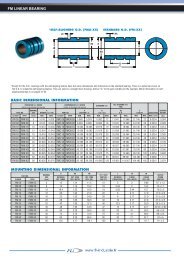
A407.5 1542.5 8091.5 165 Stroke91.5Trolley lengthNo.4 M4 fixing holes(max. 1900 mm with one length of guiding <strong>rail</strong>,for longer stroke see note on page B37)Housing for shaft Ø10 h7with 3x3 keyslot **A57* 26*43.56*2020* Position of the T-nuts of our interfaceplates (see pages B33 and B34).** In the inch versions (order codesuffix “P”), the shaft housing is Ø3/8”with 1/8” x 1/8” keyslot.A530SECTION A-A0.5 39 0.5N.2 slots2.2Ø 32Ø 14.9148.216.54051.540920LOAD CAPACITIES402.3 2.340C 0axM xM z MyC 0radC0 radN][ C0 ax[ N]Mx [ Nm]My [ Nm]Mz [Nm]8203002.8 5.6 13. 1Note: radial load C 0radis considered to be applied along the axis of the internal <strong>rail</strong>(see page B6).OTHER FEATURESMomentof inertia Iy [ cm4] 12Momentof inertia Iz [ cm4] 13. 6Maxspeed [m/s]3Weightof unit with stroke zero [g] 1459Weightof unit per meter [g]3465Massof slider [g]220Strokefor shaft revolution [mm] 85Typeof guiding <strong>rail</strong>TLV18Typeof sliderCSW18 spec. 4 rollersPitchdiameter of pulley [m]0.02706Momentof inertia of mass of each pulley [gmm 2] 5055Massof belt [g/m]41Max.Belt Tractive Force Fm ax[ N]875S tandard belt tension [ N]160Standardstarting loadless torque [Nm]0.14B elt length [ m]2 x stroke (in m)+ 0.515Cat. 41-41bEB11
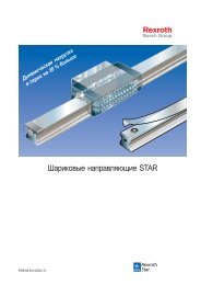
A55108 200 Stroke108Trolley length (max. 3070 mm with one length of guiding<strong>rail</strong>, for longer stroke see note on page B37)Housing for shaft Ø12 h7with 4x4 key slot **A67.5* 32.5*50.512.5*25*27.527.5* Position of the T-nuts of our interfaceplates (see pages B33 and B34).** In the inch versions (order codesuffix “P”), the shaft housing is Ø1/2”with 1/8” x 1/8” keyslot.A1.55212 28SECTION A-A0.5 54 0.5N.6 slots2.22555158.216.571Ø 47Ø 24.927.5559552.35 2.3555LOAD CAPACITIESC 0axM xM zMyC dC 0rad0 ra N][ C0 ax[ N]Mx [ Nm]My [ Nm]Mz [Nm]217575011.5 21.7 54. 4Note: radial load C 0radis considered to be applied along the axis of the internal <strong>rail</strong>(see page B6).OTHER FEATURESMomentof inertia Iy [ cm4] 34. 6Momentof inertia Iz [ cm4] 41. 7Maxspeed [m/s]5Weightof unit with stroke zero [g] 2897Weightof unit per meter [g]4505Massof slider [g]475Strokefor shaft revolution [mm] 130Typeof guiding <strong>rail</strong>TLV28Typeof sliderCSW28 spec. 4 rollersPitchdiameter of pulley [m]0.04138Momentof inertia of mass of each pulley [gmm 2] 45633Massof belt [g/m]74Max.Belt Tractive Force Fm ax[ N]1330Standardbelt tension [N]220Standardstarting loadless torque [Nm]0.22B elt length [ m]2 x stroke (in m)+ 0.630B12 U80Cat. 41-41bE
C55108 200 Stroke108Trolley length(max. 1850 mm with one length of guiding<strong>rail</strong>, for longer stroke see note on page B37)Housing for shaft Ø12 h7with 4x4 key slot **A50.567.5* 32.5*12.5*25*27.527.5* Position of the T-nuts of our interfaceplates (see pages B33 and B34).** In the inch versions (order codesuffix “P”), the shaft housing is Ø1/2”with 1/8” x 1/8” keyslot.A1.5 521228SECTION A-A0.5 54 0.5N.4 slots2.227.58.216.555Ø 47Ø 24.95571915LOAD CAPACITIES552.35 2.3555C 0axM xM zMyC dC 0rad0 ra N][ C0 ax[ N]Mx [ Nm]My [ Nm]Mz [Nm]300164018.5 65.6 11. 7Note: radial load C 0radis considered to be applied along the axis of the internal <strong>rail</strong>(see page B6).OTHER FEATURESMomentof inertia Iy [ cm4] 34. 4Momentof inertia Iz [ cm4] 45. 5Maxspeed [m/s]3Weightof unit with stroke zero [g] 2971Weightof unit per meter [g]4605Massof slider [g]549Strokefor shaft revolution [mm] 130Typeof guiding <strong>rail</strong>TLV18/ULV1 8Typeof slider2 CSW18 spec. 4 rollersPitchdiameter of pulley [m]0.04138Momentof inertia of mass of each pulley [gmm 2] 45633Massof belt [g/m]74Max.Belt Tractive Force Fm ax[ N]1330Standardbelt tension [N]220Standardstarting loadless torque [Nm]0. 3B elt length [ m]2 x stroke (in m)+ 0.630Cat. 41-41bEB13
E55Housing for shaft Ø12 h7with 4x4 key slot **108 200 Stroke108Trolley lengthA67.5* 32.5*(max. 3070 mm with one length of guiding<strong>rail</strong>, for longer stroke see note on page B37)50.512.5*25*27.527.5* Position of the T-nuts of our interfaceplates (see pages B33 and B34).** In the inch versions (order codesuffix “P”), the shaft housing is Ø1/2”with 1/8” x 1/8” keyslot.A1.5 7112 28SECTION A-A0.5 54 0.5N.5 slots2.227.58.216.5254055Ø 47Ø 24.95571915552.35 2.3555LOAD CAPACITIESC 0axM xM zMyC 0radC0 radN][ C0 ax[ N]Mx [ Nm]My [ Nm]Mz [Nm]2175150025.5 43.4 54. 4Note: radial load C 0radis considered to be applied along the axis of the internal <strong>rail</strong>(see page B6).OTHER FEATURESMomentof inertia Iy [ cm4] 34. 6Momentof inertia Iz [ cm4] 41. 7Maxspeed [m/s]3Weightof unit with stroke zero [g] 3167Weightof unit per meter [g]5055Massof slider [g]635Strokefor shaft revolution [mm] 130Typeof guiding <strong>rail</strong>TLV28/ULV1 8Typeof sliderCSW28 spec. 4 rollers / 4 CPA18Pitchdiameter of pulley [m]0.04138Momentof inertia of mass of each pulley [gmm 2] 45633Massof belt [g/m]74Max.Belt Tractive Force Fm ax[ N]1330Standardbelt tension [N]220Standardstarting loadless torque [Nm]0. 3B elt length [ m]2 x stroke (in m)+ 0.630B14 U82Cat. 41-41bE
A75116 285 Stroke116Trolley length(max. 3420 mm with one length of guiding <strong>rail</strong>,for longer stroke see note on page B37)* Position of the T-nuts of ourinterfaces plates (see pagesB33 and B34).A53.571.5* 34.5*Housing for shaft Ø14 h7with 5x5 key slot **16.2*35*36.2** In the inch versions (order codesuffix “P”), the shaft housing is Ø5/8”with 3/16” x 3/16” key slot.SPECIAL VERSIONS (upon request):A38.8Ø16 h7 with 5x5 keywayØ19 h7 with 6x6 keywayØ18 for compression couplingØ24 for compression coupling56514.536SECTION A-A2.3 70.4 2.3N.6 slots2.238.88.216.5357590Ø 5536.2Ø 29.575920754.85754.85LOAD CAPACITIESC 0axM xM z MyC dC 0rad0 ra N][ C0 ax[ N]Mx [ Nm]My [ Nm]Mz [Nm]5500185543.6 81.5 209Note: radial load C 0radis considered to be applied along the axis of the internal <strong>rail</strong>(see page B6).OTHER FEATURESMomentof inertia Iy [ cm4] 127Momentof inertia Iz [ cm4] 172Maxspeed [m/s]7Weightof unit with stroke zero [g] 6729Weightof unit per meter [g]9751Massof slider [g]1242Strokefor shaft revolution [mm] 160Typeof guiding <strong>rail</strong>TLV43Typeof sliderCSW43 spec. 4 rollersPitchdiameter of pulley [m]0.05093Momentof inertia of mass of each pulley [gmm 2] 139969Massof belt [g/m]185Max.Belt Tractive Force Fm ax[ N]4480Standardbelt tension [N]800Standardstarting loadless torque [Nm]1.15B elt length [ m]2 x stroke (in m)+ 0.792Cat. 41-41bEB15
C75116 285 Stroke116Trolley length(max. 3000 mm with one length of guiding <strong>rail</strong>,for longer stroke see note on page B37)* Position of the T-nuts of ourinterfaces plates (see pagesB33 and B34).A71.5* 34.5*53.5Housing for shaft Ø14 h7with 5x5 key slot **16.2*35*36.2** In the inch versions (order codesuffix “P”), the shaft housing is Ø5/8”with 3/16” x 3/16” key slot.SPECIAL VERSIONS (upon request):A38.8Ø16 h7 with 5x5 keywayØ19 h7 with 6x6 keywayØ18 for compression couplingØ24 for compression coupling56514.536SECTION A-A2.3 70.4 2.3N.4 slots2.28.216.57590Ø 55Ø 29.538.87536.2920754.85754.85LOAD CAPACITIESC 0axM xM zMyC 0radC0 radN][ C0 ax[ N]Mx [ Nm]My [ Nm]Mz [Nm]750435085.2 21736. 1Note: radial load C 0radis considered to be applied along the axis of the internal <strong>rail</strong>(see page B6).OTHER FEATURESMomentof inertia Iy [ cm4] 108Momentof inertia Iz [ cm4] 155Maxspeed [m/s]5Weightof unit with stroke zero [g] 6853Weightof unit per meter [g]9151Massof slider [g]1666Strokefor shaft revolution [mm] 160Typeof guiding <strong>rail</strong>TLV28/ULV2 8Typeof slider2 CSW28 spec. 4 rollersPitchdiameter of pulley [m]0.05093Momentof inertia of mass of each pulley [gmm 2] 139969Massof belt [g/m]185Max.Belt Tractive Force Fm ax[ N]4480Standardbelt tension [N]800Standardstarting loadless torque [Nm]1. 3B elt length [ m]2 x stroke (in m)+ 0.792B16 U84Cat. 41-41bE
E75116 285 Stroke116* Position of the T-nuts of ourinterfaces plates (see pagesB33 and B34).Trolley lengthA53.571.5* 34.5*(max. 3420 mm with one length of guiding <strong>rail</strong>,for longer stroke see note on page B37)Housing for shaft Ø14 h7with 5x5 key slot **16.2*35*36.2** In the inch versions (order codesuffix “P”), the shaft housing is Ø5/8”with 3/16” x 3/16” key slot.SPECIAL VERSIONS (upon request):A38.8Ø16 h7 with 5x5 keywayØ19 h7 with 6x6 keywayØ18 for compression couplingØ24 for compression coupling514.53695SECTION A-A2.3 70.4 2.3N.5 slots2.236.28.2916.520 35557590Ø 55Ø 29.54.8538.84.85757575LOAD CAPACITIESC 0axM xM zM y C0 radN]C 0rad[ C0 ax[ N]Mx [ Nm]My [ Nm]Mz [Nm]5500371085.5 163209Note: radial load C 0radis considered to be applied along the axis of the internal <strong>rail</strong>(see page B6).OTHER FEATURESMomentof inertia Iy [ cm4] 127Momentof inertia Iz [ cm4] 172Maxspeed [m/s]5Weightof unit with stroke zero [g] 7544Weightof unit per meter [g]10751Massof slider [g]1772Strokefor shaft revolution [mm] 160Typeof guiding <strong>rail</strong>TLV43/ULV2 8Typeof sliderCSW43 spec. 4 rollers / 4 CPA28Pitchdiameter of pulley [m]0.05093Momentof inertia of mass of each pulley [gmm 2] 139969Massof belt [g/m]185Max.Belt Tractive Force Fm ax[ N]4480Standardbelt tension [N]800Standardstarting loadless torque [Nm]1. 3B elt length [ m]2 x stroke (in m)+ 0.792Cat. 41-41bEB17
ED75116 330 Stroke116* Position of the T-nuts of ourinterfaces plates (see pagesB33 and B34).Trolley length49.5A53.571.5* 34.5*13536A(max. 2900 mm with one length of guiding <strong>rail</strong>,for longer stroke see note on page B37)16.2*35*36.2SECTION A-A2.3 70.4 2.35538.836.275907538.8Housing for shaft Ø14 h7with 5x5 key slot **** In the inch versions (order codesuffix “P”), the shaft housing is Ø5/8”with 3/16” x 3/16” key slot.SPECIAL VERSIONS (upon request):Ø16 h7 with 5x5 keywayØ19 h7 with 6x6 keywayØ18 for compression couplingØ24 for compression couplingN.4 slots2.28.216.5Ø 55Ø 29.592075924.85754.85LOAD CAPACITIESC 0axM xM zM yC 0radC0 radN][ C0 ax[ N]Mx [ Nm]My [ Nm]Mz [Nm]55008700400.2 696240Note: radial load C 0radis considered to be applied along the axis of the internal <strong>rail</strong>(see page B6).OTHER FEATURESMomentof inertia Iy [ cm4] 127Momentof inertia Iz [ cm4] 172Maxspeed [m/s]5Weightof unit with stroke zero [g] 9850Weightof unit per meter [g]14400Massof slider [g]3770Strokefor shaft revolution [mm]160Typeof guiding <strong>rail</strong>ULV43/ULV2 8T ype of sliderCSW43 spec. / CSW28 spec.Pitchdiameter of pulley [m]0.05093Momentof inertia of mass of each pulley [gmm 2] 139969Massof belt [g/m]185Max.Belt Tractive Force Fm ax[ N]4480Standardbelt tension [N]1000Standardstarting loadless torque [Nm]1. 5B elt length [ m]2 x stroke (in m)+ 0.920B18 U86Cat. 41-41bE
VERSION “L” (Long trolley)“L”-versions have a longer trolley mounted on two internal sliders instead of one. The load andmoment capacities obtainable, particularly the M yand M z, are much higher than those of the baseversions. For the M yand M zmoment capacities which refer to a specific trolley length please refer topage B24.A40L7.5 1542.5 = =42.5Trolley length(min/max. 240-250-260... 400 mm)N. 6 fixing holes M4StrokeTypeC0ra[N]dC0 axN][ Mx [ Nm]My [ Nm]Mz [Nm]Max stroke with max trolleylength [mm] *A40L16406005.6 from22to70from61to1921660* The values refer to the maximum length of a non joined <strong>rail</strong>. For longer strokes see note on page B37.A55L, C55L, E55LTrolley length(min/max. 310-320-330... 500 mm)TypeC0 rad[ N]C0 ax[ N]Mx [ Nm]My [ Nm]Mz [Nm]StrokeMax stroke with max trolleylength [mm] **A55L4350150023from82to225from240to6522770C55L600328037from213to525from39to961550E55L*4350300051from165to450from239to6522770* Only length 310 mm is considered standard, longer trolleys are considered special products.** The values refer to the maximum length of a non joined <strong>rail</strong>. For longer strokes see note on page B37.A75L, C75L, E75L, ED75L*Trolley length(min/max. 440-450-460... 700 mm)TypeC0 rad[ N]C0 ax[ N]Mx [ Nm]My [ Nm]Mz [Nm]StrokeMax stroke with max trolleylength [mm] **Order code:A 55 900 400 Lfamily(A, C, E...)A75L11000371087.2 from287to770from 852to22823000C75L15008700170.4 from 674to1805from116to3112610E75L*110007420171from 575to1540from 852to22823000ED75L*110008700400.2 from1174 to2305from 852to22822500* Only length 440 mm is considered standard, longer trolleys are considered special products.** The values refer to the maximum length of a non joined <strong>rail</strong>. For longer strokes see note on page B37.size(40, 55, 75)- -stroke(in mm)Trolley length(in mm)-Plong trolleyversionversion with pulley shafthousing in inchesCat. 41-41bEB19
VERSION “D”(Double trolley)“D”-versions have an extra trolley connected to the first by a toothed belt. The load and momentcapacities obtainable, particularly the M yand M z, are much higher than those of the base versions.For the M yand M zmoment capacities which refer to a specific distance between trolley centersplease refer to page B23.A40D1542.5 80165N. 4 fixing holes M47.5Distance between trolley centers(min. 235 mm, hereafter 240-245-250-... mm)StrokeTypeC0 rad[ N]C0 ax[ N]Mx [ Nm]My [ Nm]Mz [Nm]Max distance withstroke 0 [mm] *Max stroke with min.distance [mm] *A40D16406005.6 from70to570from 193to155819001660* The values refer to the maximum length of a non joined <strong>rail</strong>. For longer strokes see note on page B36.A55D, C55D, E55DDistance between trolley centers(min. 300 mm, hereafter 305-310-315-... mm)StrokeTypeC0 rad[ N]C0 ax[ N]Mx [ Nm]My [ Nm]Mz [Nm]Max distance withstroke 0 [mm] *Max stroke with min.distance [mm] *A55D4350150023from 225to2302from 652to667730702770C55D600328037from492to3034from 90to55518501570E55D4350300051from 450to4605from 652to667730702770* The values refer to the maximum length of a non joined <strong>rail</strong>. For longer strokes see note on page B36.A75D, C75D, E75D, ED75DDistance between trolley centers(min. 416 mm, hereafter 424-432-440-... mm)TypeC0 rad[ N]C0 ax[ N]Mx [ Nm]My [ Nm]Mz [Nm]Max distance withstroke 0 [mm] *StrokeMax stroke with min.distance [mm] *A75D11000371087.2 from771to6336from 2288to18788 34163000C75D15008700170.4 from 1809to13154 from312to226830242610E75D110007420171from 1543to12673 from 2288to18788 34163000ED75D1100017400800.4 from 3619to24917 from 2288to15752 28642450* The values refer to the maximum length of a non joined <strong>rail</strong>. For longer strokes see note on page B36.Order code:A 75 600 704 Dfamily(A, C, E...)size(40, 55, 75)- -stroke(in mm)distance betweentrolley centers (in mm)-Pdouble trolleyversionversion with pulley shafthousing in inchesB20 U88Cat. 41-41bE
VERSION “H”The H units are “slave units” with a COMPACT RAIL U-<strong>rail</strong> inside. The U-<strong>rail</strong> and slider allow theunits to function and absorb parallelism errors in the mounting structure. The H units consist ofthe aluminum profile, a U-<strong>rail</strong> and slider, and the trolley. There are no pulleys and there is nobelt. These units must always be mounted close together with another UNILINE actuator (notanother H unit).5 30TipoC0 rad[ N]C0 ax[ N]Mx [ Nm]My [ Nm]Mz [Nm]H404051.5H408200 0 0 13. 1H40L16400 0 0 da61a 192H40D16400 0 0 da192a 155814Note: the only loads these units can be subjected to are radial load andMz moment.401.5 5212 28TipoC0 rad[ N]C0 ax[ N]Mx [ Nm]My [ Nm]Mz [Nm]H55255571H5521750 0 0 54. 4H55L43500 0 0 da239a 652H55D43500 0 0 da652a 667715Note: the only loads these units can be subjected to are radial load andMz moment.555 6514.5 36TipoC0 rad[ N]C0 ax[ N]Mx [ Nm]My [ Nm]Mz [Nm]H75357590H7555000 0 0 209H75L110000 0 0 da852a 2282H75D110000 0 0 da2288a 1878 820Note: the only loads these units can be subjected to are radial load andMz moment.75Order codes:H 40 - 500familyHfamilyHfamilysection(40, 55, 75)section(40, 55, 75)stroke(in mm)55 - 800stroke(in mm)75 - 1000section(40, 55, 75)stroke(in mm)--400trolley length(in mm)704LDdistance betweentrolley centers (in mm)long trolleyversiondouble trolleyversionCat. 41-41bEB21
VERIFICATION UNDER STATIC LOADCALCULATIONThe values of static load rating, given on page B10, represent the maximum allowable loadsabove which a permanent deformation of the raceways could occour and consequently the runningquality could be compromised.The verification is made:- by calculating the forces and the moments acting simultaneously on the unit trolley.- by comparing these values with the corresponding load ratings.If:P r, P aare the radial and axial resultants of the external forces (N);M 1, M 2, M 3are the external moments (Nm);C 0rad, C 0ax, M x, M y, M zare the load ratings in the various directions given on page B10;C 0axM xM zM yC 0radz is the safety factor (see relative table);the result should be:If two or more of the described loads act together, the result should be:[1]The safety factor z should be lower when the dynamic forces to be added to the loads can bedetermined accurately, and higher when overloads may occour, especially dynamic loads suchas shocks and vibrations.Zneither shocks nor vibrations; smooth and low frequency reverse;high precision in assembly; no elastic yielding1 - 1.5normalassembly condition;1.5 - 2shocksand vibration; high elastic yield; high reverse frequency 2 - 3. 5Please contact our Application Engineering department if further information is required.B22 U90Cat. 41-41bE
LIFETIMELIFE CALCULATIONThe dynamic load rating C is a conventional load rating used in life calculations. The life towhich this load rating is related is 100 km. The values of C are indicated for each family of linearunit in the table below.Life, load rating and equivalent external load are related to each other by the formula:- L kmis the theoretical life in km;- C is the dynamic load rating in Newton;FamiliesA C E EDHTypeA40A55A75C55C75E55E75ED75H40H55H75C [N] 1530426012280560147042601228098151530426012280Note: for long and double trolley versions the value of dynamic load rating “C” is double.- P is the equivalent external load in Newton;The equivalent external load P is the load whose effect is equivalent to the sum of the effects offorces and moments acting simultaneously on the trolley.P can be calculated with the following formula:In the above expression the loads are considered as constant in time. Instantaneous forces donot influence the life and can therefore be disregarded.- f cis the contact factor (1 for standard trolley; 0.8 for long and double trolley versions);- f iis the service factor. It has a similar meaning to that of the safety factor z in the verificationunder static load. it is equal to:f ineither shocks nor vibrations; smooth and low frequency reverse;clean working environment; low speed (2.5 m/s) and high reversefrequency; very polluted working environment1 - 1.51.5 - 22 - 3.5- f his the stroke factor;The stroke factor f htakes account of the fact thatthe raceways are stressed more frequently whenthe slider runs short strokes with equal total run.The graph gives the values of f h(with strokeslonger than 1 m, f hremains equal to 1):f hStroke [m]Cat. 41-41bEB23
CALCULATION METHODSM Zand M YFOR LONG TROLLEY VERSIONOn page B19 the moment M zand M yload capacities relative to minimum and maximum longtrolley are shown. To calculate the moment M zand M yload capacities for other trolley lengths usethe following formulas:Where:- M znand M ynare the M zand M ymoments that refer tothe specific length of trolley (Nm);- L nis the length of the trolley (mm);- L minis the minimum length of the trolley indicatedon page B19 (mm);- k is a constant value:A4074A55- E55 110C55130A75- C75 - E75 - ED75 155ED75(M ) 270y- M z minand M y minare the minimum M zand M ymomentsindicated on page B19 (Nm);M Zand M YFOR DOUBLE TROLLEY VERSIONOn page B20 the moment M zand M yload capacities relative to minimum and maximum distancebetween trolley centers are shown. To calculate the moment M zand M yload capacities for differentdistances between trolley centers, use the following formulas:Where:- M znand M ynare the M zand M ymoments which referto the specific distance between trolley centers (Nm);- I nis the distance between trolley centers (mm);- I minis the minimum distance between trolleycenters indicated on page B20 (mm);- M z minand M y minare the minimum M zand M ymomentsindicated on page B20 (Nm);MOTOR TORQUE CALCULATIONThe motor torque C mneeded on the driving pulley can be calculated using the following formula:Where:- C mis the motor torque (Nm);Max torque for standardbelt tensionSee page B31.- C vis the standard starting loadless torque indicatedfor each family from page B11 to page B18 (Nm);- F is the force applied on the belt (N);- D pis the pitch diameter of pulley indicated for eachfamily from page B11 to page B18 (m);Please contact our Application Engineering department if further information is required.B24 U92Cat. 41-41bE
MOUNTING CONFIGURATIONSAND INSTRUCTIONSIn this chapter the most typical mounting configurations of UNILINE units are shown below.For more information about these and other configurations, please consult our applicationengineering dept.Depending on the technical characteristics (loads, speed, acceleration, etc.), your applicationmay have different requirements even if it seems to fit a particular example shown.For more information, please consult our application engineering dept.All plates mentioned in this chapter come with all the holes necessary for connecting any twounits. They also come complete with T-nuts and screws.Please note that in case the plates are used with “C” family units, some fixing holes on thesupporting profile are not used because the profiles have only one slot. This does not effect theperformance.When connecting two or more units please make sure that the connection is made to the profilebody and not the heads alone.SINGLE UNITAs the tables on page B9 show, the correct choice of UNILINE units depends heavily on the typeof loads the unit is subject to. The most important factor in the choice of a single unit is often therigidity of the system. Which family will offer the most rigidity is strictly related to the type andlocation of load the system is subject to.In an application with an Mx moment load as seen in the example below, page B9 will show thatthe “E” - “ED” families of actuators would be the best choices.EEDPARALLEL UNITSa) With syncronized drive shaft:Generally, the best solution would be a pair of “A” family actuators. Their load capacities andrigidity would give a high level of reliability to the system. Please specify “synchronized” whenordering (see page B37).b) Without syncronized drive shaft:This solution is not advisable unless the distance between the units is minimal (if the distance istoo great, a single drive could possibly cause “misalignment” of the nondriven unit’s slider inphases of acceleration/deceleration). If positioned at close distance, generally the best solutionwould be a pair of “A” family actuators or a combination of “A” family and “H” family actuators(please contact our Application Engineering department for more information).a) b)A A H ACat. 41-41bEB25
2 AXIS GANTRY (2X-Y)This example shows a gantry where the connection of the two axes is obtained by attaching thetwo parallel unit trolleys with the central unit heads by means of a pair of T-plates(Rollon part # APC-1). See detailed drawing on page B35.Unit “1”EUnit “2”AATo connect the units tomotors or reducers, use theproper interface plates (seepages B33 and B34)The mounting procedure is as follows:1. Fix the plates to unit 1, the Y-axis, by inserting the screws and T-nuts in the proper holes andslots (see Fig.1 as reference). Assure the T-nuts are rotated 90° in their slots when tightened.Recommended tightening torque is 10 Nm (max.).2. Attach plates to the unit 2 trolleys making sure to center unit 1 on the trolleys (see Fig. 2).Assure the T-nuts are rotated 90° in their slots when tightened. Recommended tightening torqueis 10 Nm (max.)Fig.1 Fig.2Unit “1”ScrewsAPC-1 plateUnit “1”T-nutsScrewsT-nutsAPC-1 plateUnit “2”B26 U94Cat. 41-41bE
2 AXIS GANTRY (Y-2Z and 2Y-Z)In the examples below two typical mounting configurations of 2-axis manipulators are shown.The difference between them is the direction of movement of the axes; in the first case the “single”axis is horizontal, in the second it is vertical. For this reason and for the fact the acting loadscould also be different, the units used are of different types (for more information, please consultour Application Engineering dept.). In both cases APF-2 mounting blocks are used. These blocksconnect the supporting profile of the single unit to the center of the trolleys of the parallel units.The mounting instructions of the blocks are on page B36.AEEDCAAAUnit “2”To connect the units tomotors or reducers,use the properinterface plates (seepages B33 and B34)Unit “2”Unit “1”Unit “1”The mounting procedure is as follows:1. Insert the projecting part of the mounting block into the lower slot of unit 1 (see page B36).2. Position the block so that the hole is 90° to the mounting surface (centered on unit 2 trolley).Insert, if necessary, a shim between the block and the trolley (shim not supplied).3. Insert the fixing screws in the block and tighten. Recommended tightening torque is 10 Nm(max.)4. Repeat steps 1-3 for the necessary number of blocks.Unit “2”Shim(not supplied)T-nutShim(not supplied)T-nutScrewUnit “1”APF-2 blockAPF-2 blockScrew Unit “2”Unit “1”Cat. 41-41bEB27
X-Y GANTRYAnother typical application of linear actuators is the “XY-gantry”. In this first example, a unit isfixed to the other by connecting its trolley and the other unit’s profile using the APF-2 mountingblocks. Consequently, the moving part of the system must be connected to the “C” family unittrolley. The mounting instructions of the APF-2 blocks are exactly as in the previous examples.To connect the units tomotors or reducers, usethe proper interface plates(see pages B33 and B34)CEEDX-Z GANTRYIn this second example, one unit is fixed to the other by connecting the two trolleys using anX-plate (Rollon part # APC-3; for a detailed drawing of the plate see page B36). Consequently,the moving part of the system will be connected to the supporting profile of the vertical unit.To connect the units tomotors or reducers, usethe proper interface plates(see pages B33 and B34)Unit “1”EDEEEDUnit “2”The mounting procedure is as follows:1. Fix the plate to unit 1 trolley by inserting the screws and T-nuts in the proper holes and slots(see Fig.1 as reference). Assure the T-nuts are rotated 90° in their slots when tightened.Recommended tightening torque is 10 Nm (max.)2. Attach plate to the unit 2 trolley making sure to center unit 1 on the trolley (see Fig. 2).Assure the T-nuts are rotated 90° in their slots when tightened. Recommended tightening torqueis 10 Nm (max.)Fig.1Unit “2”Fig.2Unit “1”APC-3 plateUnit “1”T-nutsAPC-3 plateScrewsScrewsT-nuts Unit “2”B28 U96Cat. 41-41bE
3 AXIS GANTRY (2X-Y-Z)This example is a 3-axis gantry obtained by connecting four linear actuators. The vertical axis isattached to the center unit by connecting the trolleys with an X-plate (Rollon part# APC-3; for adetailed drawing of the plate see page B36). The connection between the parallel units and thecenter one is obtained using a T-plate (Rollon part# APC-1; for detailed drawings of the platesee page B35). The plate mounting instructions are the same as the previous examples.EDETo connect the units tomotors or reducers, use theproper interface plates(see pages B33 and B34)EDEAA3 AXIS GANTRY (2X-2Y-Z)In this case, the vertical axis Z is mounted between two parallel units 2Y to improve the stiffnessof the complete assembly. The connection of the vertical profile with the trolleys of the 2Y units ismade using right-angle plates (Rollon part# APC-2; for detailed drawings of the plate see pageB35). The connection between the 2Y units and the 2X units is obtained using the APF-2 mountingblocks (for mounting instructions of the blocks see previous examples).ATo connect the units tomotors or reducers, usethe proper interface plates(see pages B33 and B34)Unit “2”Unit “1”AACAThe following are the mounting instructions for the APC-2 plates:1. Fix the plate to unit 1 trolley by inserting the screws and T-nuts in the proper holes and slots(see Fig.1 as reference). Assure the T-nuts are rotated 90° in their slots when tightened.Recommended tightening torque is 10 Nm (max.)2. Attach plate to the unit 2 profile (see Fig. 2). Assure the T-nuts are rotated 90° in their slotswhen tightened. Recommended tightening torque is 10 Nm (max.)Fig.1 Fig.2ScrewsAPC-2 plateT-nutsUnit “1”ScrewsAPC-2 plateUnit “2”T-nutsUnit “1”Cat. 41-41bEB29
MOTOR / GEARBOX CONNECTIONProper interface plates must be used in connecting a motor/reducer to the unit.ROLLON offers these plates in two different types shown on pages B33 and B34.Whether using ROLLON’s or your own plate, ensure that the mounting plate will not interfere withyour stroke. Also, it is the customer’s duty to ensure that plate and unit will properly supportmotor/gearbox weight (Call Application Engineering Department for more information).The metric plate comes with holes that mount to any unit, but they have to be “adapted” to themotor/reducer used (from this point on we will always consider the presence of a reducer betweenunit and motor). The plates have a centering bore that should be used as a reference whendrilling the reducer mounting holes. If the reducer flange covers the “plate-unit” fixing screws, the“plate-reducer” connection must be made by drilling through holes on the reducer and threadedholes on the plate. On the contrary, if the flange leaves enough space to tighten the “plate-unit”screws, depending on the reducer hole type (threaded or not), spot-faced holes on the plate(with the screw head housing on the “unit side”) in the first case, or threaded holes in the secondcase, must be drilled.Once the plates are “adapted” to the reducer, it’s possible to start mounting.The mounting procedures will be different depending on the reducer hole type (threaded or not).The following are the mounting instructions:A) Reducer with threaded holes (use the drawingson pages B33 and B34 as reference):1. Place the plate against the reducer using thecentering bore as reference and fasten using T-nuts and screws.2. Fix the reducer-plate assembly to the unit’s T-slots.3. Insert the reducer shaft into the pulley housingaligning the key with the keyseat and pushing ituntil the plate comes in direct contact with the unit.4. Tighten the screws assuring the T-nuts arerotated 90° in their slots. Recommendedtightening torque is 10 Nm (max.)Reducer fixingscrewsReducerUnitT-nutsInterface plateUnit fixing screwsMotorB) Reducer with through holes (use the drawingson pages B33 and B34 as reference):Unit1. Place the plate against the unit and fastenusing T-nuts and screws.T-nuts2. Insert the reducer shaft into the pulley housingaligning the key with the keyseat and pushing itInterface plateuntil the plate comes in direct contact with the unit.3. Attach the reducer to the threaded holes of theReducerplate. The interface plates for the A40 units comewith four fixing holes, even if only two of them areMotorused for connection; the other two holes are forsymmetry and allow the plate to be used on bothsides of the unit.Unit fixing screws4. For the “C” family one of the four holes, inparticular the one on the upper right corner (seeReducer fixing screws“standard” plate drawing on page B33), is not usedfor the connection to the unit and must be left without screw and T-nut.The motor/reducer plates for the A40 come with four mounting holes even if only two of theseare used to mount to the unit. The extra holes make the plate symmetrical and allow it to beused on any side of the unit. For C units, only three holes will be used. The upper hole on thebody will not be used to mount to the unit.B30 U98Cat. 41-41bE
BELT TENSIONINGThe UNILINE linear units are all supplied with standard belt tension suitable for most applications.See table below for values.The belt tension system located at the trolley’s end allows different belt tension settings accordingto technical requirements. For variation please follow procedure below (the reference valuesare the standard ones).1. Decide the needed belt tension variation.2. The number of turns that the tension screws “B” must be turned for the required belt tensionvariation can be found in the charts below.3. Calculate the length of the belt (in meters), with the formula:L= 2 x stroke (m) + 0.515 (for “40” size units);L= 2 x stroke (m) + 0.630 (for “55” size units);L= 2 x stroke (m) + 0.792 (for “75” size units).L= 2 x stroke (m) + 0.920 (for “ED75” units).4. Multiply the numbers of turns (step 2) by the belt length in meters (step 3).5. Loosen the set-screw “C”.6. Turn the belt tension screws “B” to the value obtained in step 47. Fasten the set-screw “C”.CBelt tension [N]400300200100040 size55 size0 0.5 1 1.5 2Turns of belt tension screws“B” per meter of beltBelt tensioning valuesAB40size 55size75sizeED75150075 size160N 220N 800N 1000 NBelt tension [N]100050000 0.5 1 1.5 2Note: the forces applied on the belt mustnever exceed the belt tension valueotherwise the repeteability of position andbelt resistance cannot be guaranteed.In case higher tension values are requiredwe suggest contacting our ApplicationEngineering department.Turns of belt tension screws“B” per meter of beltExample:To increase the belt tension from 220 N to 330 N for a A55-1070:1. Variation = 330 - 220 = 110 N.2. From the chart we find the value of 0.5 turns, which will increase the belt tension by 110 N forevery meter of belt.3. From the formula of step 3, the belt length (in meters) is:L= 2 x stroke (m) + 0.630 = 2 x1.070 + 0.630 = 2.77 m.4. The total number of turns is therefore 0.5 x 2.77 = 1.4 turns .5. Loosen the set-screw “C”.6. Turn the belt tension screws “B” 1.4 turns, using an external reference to obtain a precisesetting.7. Fasten the set-screw “C”.Cat. 41-41bEB31
LUBRICATIONUNILINE units are supplied with the internal <strong>rail</strong>s already lubricated to guarantee correct operationwithout maintenance for a period equal to about 100 km of travel. After this period, it’s necessaryto maintain the <strong>rail</strong>s to guarantee optimal performance. It is recommended that machines bestopped when performing maintenance.The lubrication procedure is as follows:- “C” family units:1. Move the trolley to one end of the unit.2. At about half the stroke press and manually move thebelt in order to see one of the two <strong>rail</strong>s inside the unit (seefigure at right).3. By using a grease syringe (not supplied by ROLLON)or an alternative tool (i.e. brush), apply a conspicuousquantity of grease on the raceways (we suggest a lithiumbased grease of medium consistency).4. Move the trolley manually back and forth for thecomplete stroke in order to distribute the grease on theoverall <strong>rail</strong> length.5. Repeat the steps 1-4 for the other internal <strong>rail</strong>.- “A” and “E” family units:Lubrication of these units is possible by following steps 1-4 of the procedure above. (For the Efamily, the lubrication of the external <strong>rail</strong> can be done by following step 3 or any other method).Furthermore, these units also have a lateral hole on the trolley, which allows the grease, bymeans of a proper conduit, to arrive directly on the raceways of the internal <strong>rail</strong>. By using thishole, lubrication can be done in two ways:1. Use of a grease syringe:When using a grease syringe, insert the needle of the syringeinto the hole and then inject the grease in the relative conduit(see figure at right).Please note that the grease has to fill the whole conduit in orderto lubricate the <strong>rail</strong> properly; for this reason, we recommend agreat quantity of grease.2. Use of an automatic greasing system:To connect the unit to an automatic greasing system, use aproper adapter/connector that attaches to the threaded holeLubrication conduiton the side of the trolley. The advantage of this solution is the possibility of <strong>rail</strong> re-lubricationwithout stopping the machine.It’s always recommended (during the maintenance period of the whole machine on which theunits are mounted or whenever a machine-stop is foreseen), to clean the <strong>rail</strong>s before lubricationin order to avoid the presence of a great amount of exhausted grease on the inside of the <strong>rail</strong>s.The cleaning can be done as follows:1. Loosen the set-screws “C” of the belt-tensioning device “A” located on the upper part of thetrolley (see figure at right).2. Loosen completely the belt tensioning screws “B” and removethe tensioning devices.3. Lift the belt in order to access the internal <strong>rail</strong>s.C4. Clean the <strong>rail</strong> raceways with a clean and dry cloth, trying toeliminate all the residual grease and dirt that can form duringAnormal operation (move the trolley first to one end of the unit andthen to the other, in order to clean the entire <strong>rail</strong> length).5. Apply a conspicuous amount of grease on the raceways (in theBmost preferred way).6. Re-insert the tensioning devices in their housings, the relativescrews and reset the belt tensioning (for this procedure, follow the instructions on page B31).7. Fasten the set-screws “C”.U100 B32Cat. 41-41bE
MOUNTING ACCESSORIESMETRIC INTERFACE PLATEThese plates come with the necessary dimensions and proper holes to mount to the units (seedrawings). The reducer/motor mounting holes can easily be drilled on the plates by the user to fitmost metric reducers/motors.All plates come with M6 screws and T-nuts for mounting to the units.Housing for M6 screws(to be used for fixing on theextrusion slots)Lmotor sideIMNunit side* Area of plate to beremoved if used for ED75(Adding 20 mm to totallength of unit will renderthis modificationunnecessary).x=20; y=35 mmDEAFx *y *BHGCUnitsizePlate codeA[mm]B[mm]C[mm]D[mm]E[mm]F[mm]G[mm]H[mm]I[mm]L[mm]M[mm]N[mm]40A40-AC211040831243.5 2017.5 1410Ø 202 Ø 3255A55-AC2126551002550.5 27.5 181510Ø 302 Ø 4775A75-AC2135701063553.5 361918.5 10Ø 352 Ø 55Order code:A40-(A40, A55, A75)AC2“NEMA” PLATEThese plates mount to the unit and to most standard NEMA sized motors or reducers. (NEMA 23for the size 40 families; NEMA 34 for the size 55 families; NEMA 42 for the size 75 families). Theposition of the holes that mount to the unit is identical to those of the “standard” interface plates.All plates come with M6 screws and T-nuts to use in mounting to the units.Order code:A40 - AC1 - P(A40, A55, A75)Cat. 41-41bEB33
- “NEMA” plates for “40” and “55” sizes:11OLMotor side36.56.6NAP2 10Unit side45°BDF90°QHGCEUnitsizePlate codeA[mm]B[mm]C[mm]D[mm]E[mm]F[mm]G[mm]H[mm]L[mm]N[mm]O[mm]P[mm]Q[mm]40A40-AC1-P11070831243.5 3517.5 29Ø 20Ø 32Ø 39Ø 5 Ø 66. 755A55-AC1-P1261001002550.5 501837.5 Ø 30Ø 47Ø 74Ø 5. 5 Ø 98. 4- “NEMA” plate for “75” size:5710.5 35Motor side7551357.145°y *90°42.512035125.713.536.5* Area of plate to beremoved if used for ED75(Adding 20 mm to totallength of unit will renderthis modificationunnecessary).x=20; y=60 mmx *2 10Unit side1953.5106U102 B34Cat. 41-41bE
“T” PLATEThis plate allows two units to be mounted perpendicular to each other as in the example onpages B26 and B29. The plate will not interfere with the strokes of either unit.It comes with M6 screws and T-nuts for mounting.This plate cannot be used for ED75 unit! (Please consult our Application Engineering Departmentfor more information).1655555 10Housing for M6 screws(to be used for fixing on the extrusion slots)6 65 54UnitsizeMounting holes onthe trolleyMounting holes onthe profile40Holes1Holes 455Holes2Holes 515075Holes3Holes 63223321165 4 561123side to put in contactwith the profileOrder code:APC - 1side to put the contactwith the trolley“RIGHT ANGLE” PLATEThis plate allows the right angle mounting of two units. The trolley of one unit can be mounted tothe side of the other as in the example on page B29. The plate will not interfere with the strokesof either unit. It comes with M6 screws and T-nuts for mounting.This plate cannot be used for ED75 unit! (Please consult our Application Engineering Departmentfor more information).6556Housing for M6 screws(to be used for fixing on the extrusion slots)7384side to put the contactwith the trolley8side to put in contactwith the profileUnitsizeMounting holes onthe trolleyMounting holes onthe profile40Holes1Holes 47532112355Holes2Holes 575Holes3Holes 6321123165Order code:APC - 2Cat. 41-41bEB35
“X” PLATEThis plate allows two units to be mounted perpendicular to each other as in the examples onpages B28 and B29. The plate will not interfere with the strokes of either unit.It comes with M6 screws and T-nuts for mounting.6 6Housing for M6 screws(to be used for fixing on the extrusion slots)5 516052.5 553322114 44 45 5112233UnitsizeMounting holes forfirst unit trolleyMounting holes forsecond unit trolley40Holes1Holes 455Holes2Holes 575Holes3Holes 66 652.5 5516010Order code:APC - 3MOUNTING BLOCKMultiple mounting blocks are used to mount a unit to a mounting surface. They can also be usedto mount two units together with or without an interface plate (see examples on pages B27, B28and B29). The blocks will fit in any of the T-slots in each of the units.8.5A5 357.3 2040A420No. 2 holes Ø 4.5Ø 6.515 7.530Section A-A- Insert the projecting part of the mounting blockinto the lower slot of the unit aluminum profile;- Position the block longitudinally, in accordancewith the holes position on the supportingstructure. Insert, if necessary, a shim (notsupplied) between the block and the supportingplane;- Insert the screw/screws into the block andtighten.Order code:APF - 2T-NUTSAll UNILINE unit profiles have 8 mm slots, in which it’s possible to use T-nuts with M4, M5 andM6 holes. ROLLON can supply sets of 100 pieces of T-nuts with M6 holes. Recommendedtightening torque is 10 Nm (max.)7.91.56Order code:M616.5KIT - 4 (set of 100 pcs.)U104 B36Cat. 41-41bE
OTHER USEFUL INFORMATIONRUNNING PARALLELISMRunning parallelism for all standard families and sizes is equal to 0.8 mm (see drawing below):REPEATABILITY OF POSITIONINGRepeatability of positioning is equal to 0.1 mm for all standard families and sizes.UNITS USED IN PAIRSWhen multiple units are to be mounted parallel and run together using a connecting shaft, indicatein the order that the key slots of the pulleys must be synchronized.EXTRA LONG UNITSUnits of considerable length are possible. These units are sometimes difficult to transport andmay have to be shipped disassembled. Please contact our Application Engineering departmentfor more information.DIMENSIONAL TOLERANCES ON STROKESAND LENGTHSIn order to always guarantee the minimum stroke required, the actuators will have positivetolerances. These tolerances can be quantified relative to the stroke of the unit:For strokes < 1m: +0; +10mm;For strokes > 1m: +0; +15mm;For strokes greater than standard, the tolerances could be slightly higher.WORKING TEMPERATUREThe working temperature range is -20°C / +80°C (-4°F / +176°F).Cat. 41-41bEB37
LINEAR ACTUATOR A100CThe ROLLON linear actuator simply and reliably solves the problems of a moving axis.Fully interlocked multi-axis robots can be quickly established by fixing one or more actuators toa basic structure and then adding motors and drive controls.The ProblemUp to now, linear actuator could be divided into two categories: units using ball recirculatingsystems and units using rollers. Although the ball recirculating actuators offer high load capacityand stiffness, they are generally oversized compared to their structural profile. They are very noisyand unable to work at high speed because of the constraints inherent in the ball recirculatingsystem.b Until now, actuators using rollers, while capable of high speed and less noise, havebeen undersized compared to their structural profile and limited by low load capacity andmoderate stiffness. The most complete versions have rollers made by profiled ball bearingsrunning on steel rods which are only partially sunk into the outside of the structural profile andtherefore remain visible.In general, rollers are no more than plastic covered ball bearings running directly onto aluminum.ROLLON's solutionThe original design of the ROLLON linear actuator A100C has been achieved after extensivedevelopment and use of FEM techniques. The A100C combines the high load capacity, stiffnessand <strong>compact</strong>ness of a ball recirculating actuator with the high speed and low noise of a actuatorwith rollers. The result is an optimal integration of structural profile, <strong>rail</strong> and linear slide.Completely enclosed system withlongitudinal seals and brushes inthe headsBelt tensioning systemincorporated in the headHeads arealuminiumcastingsPolyurethane toothed beltwith internal steel cablesLinear bearing with rollers offershigh stiffness and load capacity(COMPACT RAIL System)Fixture for electricmotor connectionExtruded self-supportinglight alloy structural profileU106 B38Cat. 41-41bE
The linear slide inside the actuator is from the ROLLON COMPACT RAIL system, which is basedon the original concept of a slider with rollers running inside a carbon steel channel-shaped <strong>rail</strong>.The raceways are induction hardened and positioned internally for protection. The section, the<strong>rail</strong> profile and slider rollers have been optimised using FEM techniques. The rollers comprise aprecision double row angular contact ball bearing with an internal eccentric pivot. The extra-thickouter ring is profiled for optimum running inside the <strong>rail</strong>. The result is a slide-roller system havinghigh axial/radial load capacity and high stiffness. The internal eccentric pivots allow adjustmentof the rollers in order to achieve a required preload suited to the application. The extrudedstructural profile has been carefully proportioned to obtain a balance between stiffness of the slideand stiffness of the profile. The external sides of the structural profile have tee slots to allow theactuator to be easily fixed to support structures or other profiles. Transmission is achieved byusing a polyurethane toothed belt of the AT series, which has been reinforced with internal steelcables to give low extention, very high stiffness, resistance to wear and reliability with a nomaintainanceguarantee. The motor heads are aluminum castings. One incorporates the belttension system, while the other contains the driving pulley and the fixtures for the attachment ofthe motor on both sides. The linear actuator is available in two versions:- Version A: The driving pulley is fitted with a hollow shaft with a key slot. If the application requiresa double projecting shaft solution, a slotted shaft (included with the unit) may be inserted into thehollow shaft.- Version B: The driving pulley is fitted with a smooth hollow shaft that can be attached to the motorby compression coupling.The mechanical movement is completely protected by longitudinal seals and brushes in theheads.DimensionsL = 540 + stroke123 stroke3001177947 556557.532.5 45 19.510.3100 20.1122.51051007 6Attachments on the sliderM6 holes for end-stroke sensors (on both sides)Adjustableeccentric rollersBelt-lockingscrews1010252020 2545Fixed rollersLubricating nipple35 35 130 35M8 fixing holesCat. 41-41bEB39
Motor connections: version AM 619*39.516819*66568465101Hollow shaft for key slot A 6 x 6 x 32 ISO773Version A offers two possibilities:2Slotted shaft (with keyslot A 6 x 6 x 32 ISO773with snap rings(included with actuator)19*31.3 31.3Dimensions withshaft inserted* 20 mm available upon request!a) the hollow shaft with the key slot allows direct connection through an appropriate interface plateto a motor (or reducer) with a projecting shaft.b) inserting the slotted shaft into the hollow shaft of the driving pulley, a motor and an eventualintermediate shaft can be connected to the head by a sleeve joint giving a double projecting shaftsolution. In this case a joining box containing the sleeve joint must be obtained.a)b)Sleeve jointMotor Reducer Interface plateMotorJoining boxMotor connections: version BThe smooth hollow shaft allows the drivingpulley to be connected to the motor shaftby compression coupling. If the motorshaft is Ø19, ROLLON’s compressioncoupling (available as an accessory, seeAccessories) can be attached to the insideof the hollow shaft, avoiding unnecessaryencumbrance between the motor and thehead.In this case an appropriate interface plate,connecting the coupling flange of themotor to the motor head, must be procured.6565M 6101244 239.568Compression couplingExternal connector16MotorInterface plateU108 B40Cat. 41-41bE
NotesThe linear actuator is supplied with a factory assembled and adjusted slider, in order to obtain thesmoothest slide without play; this adjustment is suitable for the majority of applications.If needed, it’s possible to modify the adjustment by acting on the two central rollers (ask forinformation from the ROLLON Technical Service).The belt has a factory preload of 1000 N per arm, but can be adjusted using the two regulatingscrews on the tension head.The belt preload value must be determined in function of the force acting on the belt when working.To obtain the best position precision, the belt tension must always be greater than the forcetransmitted, depending on the loads applied and the unit’s law of motion. If the belt preload ischanged, the correct alignment of the driven pulley can be verified by removing the lids on thesides of the head (ask for information from the ROLLON Technical Service).The torque applied to the drive pulley, necessary to move a loadless slider horizontally withstandard belt tension, is equal to 2.3 Nm. If the belt tension is increased, the torque requiredincreases.AccessoriesCompression couplingOrder code: AC-10MA012419M 66.3 842.9 10Max torque transmissible: 63 NmCat. 41-41bEB41
Technical characteristics of the standard versionPaMxPrMyMzU110 B42Cat. 41-41bE
4545Special versionsSpecial versions of linear actuator with a longer slider or with two sliders can be provided uponrequest.Linear actuator with long slider (A100CL)L = 644 + stroke404stroke4535 35 234 35This actuator offers higher loadmoments due to the extendedlength of the slider.Linear actuator with two sliders (A100CD)L = 540 + distance between the centers of sliders + strokedistance between the centers of slidersstroke35 35 130 3530035 35 130 35300This actuator offers notably higherM yand M zload moments whichvary in function of the distancebetween the centers of the sliders.Cat. 41-41bEB43
Order codesStandard linear actuator A100CA100C - 800 - AFamilyStroke(in mm)Motor connectionversion (A or B)The available strokes are from 170 to 3420 mm, with intermediate sizes every 50 mm.Linear actuator with long slider A100C...LA100C - 900 - 404 L - AFamilyStroke(in mm)Slider length(in mm)Longer sliderversionMotor connectionversion (A or B)The available strokes are from 166 to 3316 mm, with intermediate sizes every 50 mm.Linear actuator with two sliders A100C...DA100C - 600 - 704 D - BFamilyStroke(in mm)Distance betweencenters of slider(in mm)Double sliderversionMotor connectionversion (A or B)The available strokes are from 174 to 3024 mm, with intermediate sizes every 50 mm.The distances available between the centers of the sliders are from 396 to 996 mm,with intermediate sizes every 50 mm.The sum of the stroke and the distance between the sliders cannot be more than 3420 mm.U112 B44Cat. 41-41bE
INSERTOTELESCOPIC RAIL
U114INSERTOTELESCOPIC RAIL
INDEXTELESCOPIC RAIL: BEARINGS THAT MOVE OUTSIDE THE BOX...........................C4PRODUCT OVERVIEW.............................................................................................C5LOAD CAPACITIES..................................................................................................C6WHAT MAKES ROLLON’S TELESCOPIC RAILS THE WORLD’S BEST?..................C7APPLICATIONS EXAMPLES.....................................................................................C8DS SERIES.............................................................................................................C10DSS LOCKING SYSTEM.........................................................................................C12DE SERIES.............................................................................................................C14DBN SERIES..........................................................................................................C16LTF44 SERIES........................................................................................................C18ASN SERIES...........................................................................................................C19DMS63 SERIES......................................................................................................C22PRODUCT SELECTION..........................................................................................C24VERIFICATION OF STATIC LOAD...........................................................................C25SPEED...................................................................................................................C25OPENING AND CLOSING FORCE..........................................................................C25LIFETIME...............................................................................................................C25TECHNICAL APPLICATION SUGGESTIONS...........................................................C26TEMPERATURE......................................................................................................C26ANTICORROSIVE PROTECTION............................................................................C26LUBRICATION........................................................................................................C26Cat. 41-41bEC3
TELESCOPIC RAIL: BEARINGSTHAT MOVE OUTSIDE THE BOXROLLON’s TELESCOPIC RAIL products are so different from existing drawer slides that we hesitateto call them by that name. The idea behind TELESCOPIC RAILs was to create a linear bearingthat telescoped beyond its mounting structure. Our engineers had to think outside the box to dothis since this sort of product really didn’t exist.Before ROLLON attacked the problem, drawer slides were simple, bent steel products suited fordesk drawers, filing cabinets, keyboard trays and other light duty applications. In fields wherehigh load capacities, reliability, low deflection, and smoothness of movement are important for adrawer slide-type extension, there has never really been a solution. Engineers were forced touse homemade solutions or to double up on thicker gauge bent steel drawer slides.Drawer slides existed and linear bearings, of course, but drawer slides that could be used 24/7with high loads and good precision were nowhere to be found. With our TELESCOPIC RAILfamily, our engineers succeeded in creating a telescopic linear bearing – similar in movement toa drawer slide but in function closer to a linear bearing.ROLLON’s family of TELESCOPIC RAILs are the industry leader.TELESCOPIC RAIL products are made from cold-drawn bearing steel – never from bentsheet metal.TELESCOPIC RAIL products have hardened 60 HRc races to provide the smoothestmovement at all times.TELESCOPIC RAIL work well with shocks and vibrations that render other slides inoperativeimmediately.TELESCOPIC RAIL products have minimal deflection at the tip of the fully extended slide –even while carrying maximum loads.TELESCOPIC RAIL products can reach strokes of over 2 m (6.5 ft) in one direction and candouble that by doing the same out the other side.The TELESCOPIC RAIL family contains the following types of products:• Telescopic slides with hardened races• Telescopic slides with non-hardened races• Semi-telescopic slides with <strong>rail</strong>s that extend more than half of their length out of either side ofthe fixed part of the slide.Fixed memberIntermediate memberMoving memberEndstopsInternal ball cageNote: This drawing refers to DS series.U116 C4Cat. 41-41bE
PRODUCT OVERVIEWAll of the <strong>rail</strong>s in the TELESCOPIC RAIL family are constructed from cold-drawn carbon steel.There are five different families which can be divided into completely telescopic slides withinduction hardened races (DS, DE, DBN), completely telescopic slides without hardened races(LTF44), and semi-telescopic <strong>rail</strong>s with induction hardened races (ASN).• “DS” SERIESThis slide is formed by identical fixed and moving memberswith hardened raceways and an S-shaped intermediatemember. This thin, space saving configuration gives the slidesvery high load capacities and rigidity.DS2884DS431201728• “DE” SERIESThis slide is formed by identical fixed and moving membersand an I-shaped intermediate member. This configuration’sshort, almost square, configuration gives the slides very rigidmovements and very high radial load capacities.DE22DE35222235DE28DE432628433444• “DBN” SERIESThis slide is formed by identical fixed and moving memberswith hardened, internal raceways and an almost squareintermediate member. This <strong>compact</strong> configuration gives theslides similar load capacities for both radial and axial loads.DBN22DBN3522342235DBN28DBN4326442843FULLY TELESCOPIC WITH NON-HARDENED RACES:• “LTF44” SERIESLTF4444This slide is formed by a fixed member, an identical movingmember and an S-shaped intermediate member.This non-hardened slide saves space due to its unique profile.11.25• “ASN” SERIESThis slide is formed by a fixed member and a differently shapedmoving member. Both members have hardened raceways.This thin slide offers semi-telescopic movement. The movingmember can extend over half its length out one side of thefixed member (it can also provide the same movement out theopposite side).ASN3517ASN221135ASN432222ASN284313ASN63286329Cat. 41-41bEC5
LOAD CAPACITIESThe load capacities listed below are calculated with the <strong>rail</strong>s used in pairs, in their fully extendedposition and with the load applied in the center of mass of the moving members. Load capacitiesper pair are listed below in order to give an idea of the strength of the slides (Please see thefollowing pages for a complete list of single <strong>rail</strong> load capacities).The values in the tables refer to a pair of <strong>rail</strong>s.• “DS” SERIESC 0radNote: Dimensions are in mm; “2 x C 0rad” is in newton and represents the maximum applicable load to a pairof <strong>rail</strong>s.• “DE” SERIESC 0rad• “DBN” SERIESNote: Dimensions are in mm; “2 x C 0rad” is in newton and represents the maximum applicable load to a pairof <strong>rail</strong>s.C 0rad• “LTF44” SERIESNote: Dimensions are in mm; “2 x C 0rad” is in newton and represents the maximum applicable load to a pairof <strong>rail</strong>s.C 0rad• “ASN” SERIESNote: Dimensions are in mm; “2 x C 0rad” is in newton and represents the maximum applicable load to a pairof <strong>rail</strong>s.C 0radNote: Dimensions are in mm; “2 x C 0rad” is in newton and represents the maximum applicable load to a pairof <strong>rail</strong>s.U118 C6Cat. 41-41bE
WHAT MAKES ROLLON’S TELESCOPICRAILS THE WORLD’S BEST- SMOOTHNESS OF MOVEMENTWhen choosing a telescopic slide, this key factor is often overlooked. This is unfortunate because,in the field, it is often the most important factor. After all, a slide that moves poorly is at best,frustrating and at worst, dangerous.Smoothness of movement is an area where ROLLON’s TELESCOPIC RAIL slides excel. In fact,a quick analysis of the slides’ characteristics reveals that the induction hardened races allowsmooth and sturdy movement even at the maximum capacity listed in the catalog. The hardenedraceways allow this same sweet movement even when impacts, shocks, and vibrations are present.This type of smoothness is difficult to obtain from slides made from bent sheet metal or aluminumunder the best of circumstances and is near impossible to in active environments. The nonhardenedraceways of lesser quality slides will tend to permanently deform or brinell in typicalapplications which will cause difficult, uneven movement or even failure. ROLLON’s TELESCOPICRAIL slides are rigid enough to allow only minimal deflection at maximum capacity (see below).This is important because when closing a slide, if there is deflection, the applied load must bepushed up an inclined plane. TELESCOPIC RAIL slides provide such smooth movement, therereally is no other choice.- HIGH LOAD CAPACITYThe load capacity is clearly one of the most important factors evaluated when choosing atelescopic slide. ROLLON’s TELESCOPIC RAIL slides combine high load capacity with <strong>compact</strong>dimensions. Many drawer slide manufacturers present industrial slides in their catalogs andgive them relatively high load capacities. This can cause confusion when compared to aTELESCOPIC RAIL slide with an obviously stiffer and higher quality design but with a similarcapacity. It is therefore important to note that the load capacities indicated in this catalog reflectthe maximum working loads that the slide will carry in a continuing, repetitive manner – ie. twentyfourhours a day, seven days a week. ROLLON’s TELESCOPIC RAIL slides are actual telescopiclinear bearings and not “drawer slides” and are therefore designed to be lasting, workingcomponents.- EXTREMELY LIMITED DEFLECTIONAll of the elements in the TELESCOPIC RAIL slides have been designed to remain as stiff aspossible and to allow as little deflection as possible in the fully extracted position. As mentionedbriefly above, the smoothness of movement depends heavily on the lack of deflection in theextracted position. The load on a slide that deflects when opened must be lifted and pushed upan inclined plane in order to close. Oversize actuators and motors that are often needed tocompensate for this lifting and pushing movement do not need to be specified due to the rigidityprovided by ROLLON’s TELESCOPIC RAIL slides. The eccesive manual labor and effort neededto move a deflecting drawer slide is certainly not needed to close a TELESCOPIC RAIL slide.The mechanical and economical advantages of our high-quality slides are notable.- ASSEMBLING ACCURACYROLLON is able to guarantee extreme quality, accuracy, and reliability for all of the componentsof the TELESCOPIC RAIL family. Smooth movement, lack of play, and low coefficient of frictionseparate these <strong>rail</strong>s from industrial “drawer slides” found elsewhere. When choosing a telescopicslide, there really is no other choice.Cat. 41-41bEC7
APPLICATION EXAMPLESThe slides in the TELESCOPIC RAIL family can be used in a multitude of application fields andin many different configurations. Although most typical applications use a pair of slides mountedparallel, the quality, high load capacities, and low deflection offered by these slides allow thedesign engineer an opportunity to creatively use other configurations to best solve an application.TRAIN BATTERY EXTRACTIONDSVEHICLE HANDICAP STEPDEU120 C8Cat. 41-41bE
ELECTROMEDICAL BEDASNLTF44MACHINE TOOL DOORENCLOSURESDBNDEPRODUCT EXPOSITION UNITSOTHER APPLICATION EXAMPLES:- Train, subway, and light <strong>rail</strong> cars and buses: Internal and external door movements, extendingluggage carriers, etc.- Industrial automation: telescopic press arms, product extraction and retrieval systems, etc.- Other sectors where it is necessary to extract, expand, move, or extend.Cat. 41-41bEC9
Order code:DS S 28 -DS SERIESThe new DS series telescopic slide is formed by a fixedmember and an identical moving member - both with hardened,internal raceways - and an S-shaped intermediate member.The characteristic S-shaped member gives the slide a veryhigh moment of inertia of mass which in turn allows the slideto be very thin and yet extremely strong and rigid. This rigidityand high load capacity translates to very low deflection evenwhen the <strong>rail</strong> is loaded and in a completely open position.This is true for both long and short strokes. The DS series isavailable in two sizes: size 28 and size 43. These sizes referto the outside dimensions of the fixed and moving membersof the slides.The DS series <strong>rail</strong>s have built in catches with rubber endstopsthat will stop the slide for slow manual movements. For fast orautomatic movements, we suggest adding external endstopsto the structureThe DS series <strong>rail</strong>s are available with single direction ordouble direction strokes.-Single direction stroke (version “S”). The moving membercan extend out of only one side of the slide. It moves slightlymore than its total length.-Double direction stroke (Version “D”). The moving membercan extend out of both sides of the slide. The movementallowed out each side is slightly less than the member’s totallength. It is important to note that the intermediate member ofall “D” version slides can freely move slightly less than half itslength in either direction when the slide is closed. Whenclosing a “D” version slide, the return of the intermediatemember is not automatic. When the moving element hasstarted the stroke in the opposite direction, it will catch theintermediate member and force it to return. The members havecatches with rubber endstops for this purpose.PLEASE CONSIDER THAT INTERNAL CATCHES CANNOT BEUSED TO BLOCK THE MOVING LOAD, EXTERNALENDSTOPS MUST BE ADDED!The DS series slides are designed to be mounted so that theapplied load acts in a radial direction in respect to the slide.Upon request, slides with special length strokes can beordered. For single direction stroke versions (“S” versions),special strokes can be up to 130% of the closed length of theslide while still maintaining high load capacities and lowdeflection. For more information, please contact ourengineering department.610 - 668Countersunk hole for M8 screw (DIN7991)Countersunk hole for M5 screw (DIN7991)5235Scale 1:1DS28DS43281784120SeriesVersion(S or D)Height offixed member(28 or 43)Length of fixedmemberStroke H(if different fromstandard only)Note: For special versions, the stroke H can only vary from thestandard values listed on the next page by a multiple of thefollowing values:DS..28…: 19 mm (Example: DSS28-930-969)DS..43…: 30 mm (Example: DSS43-1010-1066)U122 C10Cat. 41-41bE
- Single direction stroke (version “S”):Weight DS28: 7.9 kg/mWeight DS43: 14.6 kg/mC 0radm n n n n mLength LMoving memberStroke HFixed memberIntermediate memberNote: Load C 0radis intended for single telescopic <strong>rail</strong>- Double direction stroke (version “D”):Note: Load C 0radis intended for single telescopic <strong>rail</strong>Intermediate memberFixed memberStroke Hm n n n n mLength LStroke HMoving memberNote: Load C 0radis intended for single telescopic <strong>rail</strong>Note: Load C 0radis intended for single telescopic <strong>rail</strong>Cat. 41-41bEC11
“DSS” LOCKING SYSTEM(only for closed position)The DSS series TELESCOPIC RAIL heavy duty drawer slide comes with end-stops in thecompletely open and closed position.While these stops are designed to stop the slide from over extending in manual movements,they will not stop any external forces such as vibrations or inclined planes from moving theloaded slide. In many applications it is necessary to block the <strong>rail</strong>s in place in a completelyclosed position.Most applications in the transportation sector have this need. Whether train, bus, camper, naval,or military applications, there is frequently a need to have slide movement blocked during vehiclemovement and released only when desired.Our robust blocks are able to stop elevated longitudinal forces of up to a 3G acceleration withthe maximum loads (over 2500 lbs) applied to a pair of <strong>rail</strong>s. The stops themselves are simple:push down the lever and free the slide from the closed position.Like the slides, the locks are zinc plated but can be ordered with chemical nickel plating forelevated corrosion resistance. ROLLON recommends using one block per slide if used in pairs.U124 C12Cat. 41-41bE
TECHNICAL DATA:DLCALtotBStrokeTypeL LtotA B C DD SB28 from 290 to 1490*L+ 5284176335D SB43 from 530 to 1970*L+ 69120289545* For more information including information about our DSS heavy duty drawer slides(Telescopic Rail), please see page C11. Please also feel free to contact ourApplication Engineering Department.TypeF ax(Nm)DSB282460F maxDSB435630Order code (<strong>rail</strong> with locking system):DS B 28 -610 - 668SeriesVersion withlocking systemHeight offixed member(28 or 43)Application examples:- Trains: battery cages, doors- Electronic racksLength of fixedmemberStroke(if different fromstandard only)- Military- NavalCat. 41-41bEC13
DE SERIESThis slide is formed by identical fixed and moving members andan I-shaped intermediate member and is almost square. The I-shaped intermediate member allows the <strong>rail</strong>s to carry high loadsespecially when the load is applied in a radial direction (referringto the drawings at right, the load would be vertical). The loadcapacity for loads applied axially is lower. When mounted, thisslide offers a single direction stroke equal to slightly more thanthe closed length. Please consult our engineering departmentfor more information.Both the fixed and moving element can be supplied withcountersunk mounting holes (as in the drawings at right) byindicating the letter “V” when ordering or with threaded throughholes (M4 for DE22, M5 for DE28, M6 for DE35 and M8 for DE43)by indicating the letter “F” when ordering.A double direction stroke is obtainable by removing the endstopscrews at the end of each side of the intermediate member. Theslide will not disassemble with the removal of these screws dueto a system of built-in pins. (Although the pins are strong enoughto stop the ballcage and to return the intermediate member, theyare not designed to stop a moving member carrying a load.External endstops must be added for this purpose). It is importantto note that when the endstop screws are removed, theintermediate member can freely move slightly more than half itslength out either side. When closing a DE slide with the endstopscrews removed, the return of the intermediate member is notautomatic. When the moving element has started the stroke inthe opposite direction, it will catch the intermediate member andforce it to return.The stroke H listed on the next page refers to a single directionstroke. With the endstop screws removed as explained above,the stroke is equal to 2H.Upon request, slides with special length strokes can be ordered.Special strokes can be up to 130% of the closed length of theslide while still maintaining high load capacities and lowdeflection. For more information, please contact our engineeringdepartment.352822Scale 1:134DE22DE282622DE35Countersunk hole for M4screw (DIN7991)Countersunk hole for M5screw (DIN7991)Countersunk hole for M6screw (DIN7991)44DE43Order codes:DE F 35 - 690 - 806Series Type of hole(“F” for threaded orHeight ofintermediateLength of fixedmember“V” for countersunk) member(22, 28, 35, 43)Stroke H(if different fromstandard only)43Countersunk hole for M8screw (DIN7991)Note: For special versions, the stroke H can only vary fromthe standard values listed on the next page by a multiple ofthe following values:DE..22…: 15 mm (Example: DEF22-210-237)DE..28…: 19 mm (Example: DEV28-290-315)DE..35...: 24 mm (Example: DEV35-450-518)DE..43...: 30 mm (Example: DEF43-930-996)U126 C14Cat. 41-41bE
end-stop screwWeight DE22: 2.5 kg/mWeight DE28: 4.0 kg/mWeight DE35: 6.1 kg/mWeight DE43: 10.5 kg/mC 0radm n n mFixed member Moving memberStroke HLength LStroke HIntermediate memberNote: Load C 0radis intended for single telescopic <strong>rail</strong>Note: Load C 0radis intended for single telescopic <strong>rail</strong>Note: Load C 0radis intended for single telescopic <strong>rail</strong>Note: Load C 0radis intended for single telescopic <strong>rail</strong>Cat. 41-41bEC15
DBN SERIESThis slide is formed by identical fixed and moving membersand an almost square-shaped intermediate member. Thissturdy intermediate member allows the <strong>rail</strong> to be mountedwith the load acting radially or axially while practicallymaintaining the same load capacity (listed on the next pageas C0rad). When mounted, this slide offers a single directionstroke equal to slightly more than the closed length.A double direction stroke is obtainable by removing theendstop screws at the end of the fixed and moving members.The slide will not disassemble with the removal of thesescrews due to a system of built-in pins. (Although the pinsare strong enough to stop the ballcage and to return theintermediate member, they are not designed to stop amoving member carrying a load. External endstops mustbe added for this purpose). It is important to note that whenthe endstop screws are removed, the intermediate membercan freely move slightly more than half its length out eitherside. When closing a DBN slide with the endstop screwsremoved, the return of the intermediate member is notautomatic. When the moving element has started the strokein the opposite direction, it will catch the intermediatemember and force it to return.The stroke H listed on the next page refers to a singledirection stroke. With the endstop screws removed asexplained above, the stroke is equal to 2H.Upon request, slides with special length strokes can beordered. Special strokes can be up to 130% of the closedlength of the slide while still maintaining high load capacitiesand low deflection. For more information, please contactour engineering department.352822R 1R 3Scale 1:1DBN22DBN28DBN35342622Countersunk hole for M4screw (DIN7991)Countersunk hole for M5screw (DIN7991)Countersunk hole for M6screw (DIN7991)Order codes:SeriesDBN 22 - 370 - 422Height of fixedmember(22, 28, 35, 43)Length of fixedmemberNote: For special versions, the stroke H can only vary fromthe standard values listed on the next page by a multiple ofthe following values:DBN22…: 15 mm (Example: DBN22-450-477)DBN28…: 19 mm (Example: DBN28-530-567)DBN35…: 24 mm (Example: DBN35-850-910)DBN43…: 30 mm (Example: DBN43-1170-1236)Stroke H(if different fromstandard only)43R 2.5R 244DBN43Countersunk hole for M8screw (DIN7991)U128 C16Cat. 41-41bE
end-stop screwWeight DBN22: 2.5 kg/mWeight DBN28: 4.0 kg/mWeight DBN35: 6.3 kg/mWeight DBN43: 11.1 kg/mC 0radm n n mStroke HLength LStroke HFixed memberIntermediate memberMoving memberNote: Load C 0radis intended for single telescopic <strong>rail</strong>Note: Load C 0radis intended for single telescopic <strong>rail</strong>Note: Load C 0radis intended for single telescopic <strong>rail</strong>Note: Load C 0radis intended for single telescopic <strong>rail</strong>Cat. 41-41bEC17
LTF44 SERIESThis slide is formed by a fixed member, an identical movingmember and an S-shaped intermediate member. Built from colddrawncarbon-steel, this <strong>compact</strong> slide with non-hardenedraceways offers an excellent solution where space is limited.The LTF44 is perfect for applications without continuous repeatedmovements (In cases of continuous movements, we recommendslides with hardened raceways like the DS, DE, and DBN series).The S-shaped intermediate member transmits the load from themoving element to the fixed through a double row of ballbearings. This design allows low deflection even when the slideis completely open.The fixed (top) member must be mounted to the fixed structureand the moving member to the mobile structure using all of thethreaded holes.Both members must be mounted to a plane and rigid structuresince they will assume the same rigidity and planarity as themounting surface.Although the slides have pins strong enough to stop the ballcageand to return the intermediate member, they are not designedto stop a moving member carrying a load.External endstops must be added for this purpose.43M5R 1.5Scale 1:111.25M520Weight LTF44: 2.7 kg/m15 25 m n n m 25 15Length LStroke HC 0radFixed memberIntermediate memberMoving memberNote: Load C 0radis intended for single telescopic <strong>rail</strong>Order code:LTF 44 - 500Series Height of slide Length of fixedmemberNote: Load C 0radis intended for single telescopic <strong>rail</strong>U130 C18Cat. 41-41bE
ASN SERIESThis slide is formed by a fixed member and a differently shaped moving member of the samelength. Both members have hardened raceways.This thin slide offers semi-telescopic movement. The stroke H is reached when the moving memberextends over half its length out one side of the fixed member. By removing the end stop screw atthe end of the fixed member, a double direction stroke equal to 2H (slightly longer than theclosed <strong>rail</strong> length) can be reached. (Removal of this screw will not cause the slide to disassemble).This means that the moving member will move more than half its length out one side of the <strong>rail</strong>and more than half its length out the other.ASN series slides can be used in both horizontal and vertical applications. For more information,please consult our application engineering department.Although the slides have pins strong enough to stop the ballcage and to return the intermediatemember, they are not designed to stop a moving member carrying a load.External endstops must be added for this purpose.Upon request, slides with special length strokes can be ordered. Special strokes can be up to65% of the closed length of the slide while still maintaining high load capacities and low deflection.For more information, please contact our engineering department.Order codes are listed on page C21.10R27.5 R111.3M4ASN226.5 R310.2511Countersunk hole for M4screw (DIN7991)2215M5ASN2812.2513Countersunk hole for M5screw (DIN7991)2815.8M6ASN3516.517Countersunk hole for M6screw (DIN7991)3510.52x45°23M813.5R2.5Countersunk hole for M8screw (DIN7991)4329.3M8Counterbored hole for M8 socket headcap screw with low head (DIN7984)63ASN432122ASN632829Scale 1:1Cat. 41-41bEC19
end-stop screwM zC 0axFixed memberWeight ASN22: 1.2 kg/mWeight ASN28: 2.0 kg/mWeight ASN35: 3.0 kg/mWeight ASN43: 5.2 kg/mWeight ASN63: 10.3 kg/mM yM xm n n mC 0radStroke HLength LStroke HMoving memberNote: Subsequently all the load capacities are intended for single <strong>rail</strong>:U132 C20Cat. 41-41bE
Order code:ASN 63 - 770 - 433SeriesHeight of slide(22, 28, 35, 43, 63)Length of fixedmemberStroke H(if different fromstandard only)Note: For special versions, the stroke H can only vary from the standard values listed on thesepages, by a multiple of the following values:ASN22…: 7.5 mm (Example: ASN22-290-161)*ASN28…: 9.5 mm (Example: ASN28-370-199)*ASN35…: 12 mm (Example: ASN35-530-291)ASN43…: 15 mm (Example: ASN43-690-378)ASN63…: 20 mm (Example: ASN63-930-503)* Round all strokes down to the nearest whole number.Cat. 41-41bEC21
DMS63 SERIESTELESCOPIC RAILS WITH HIGHEST CAPACITY LOADWith DMS63 TELESCOPIC RAIL series, ROLLON introduces a new linear solution to move veryheavy structures maintaining high stiffness.The strength of the system is guaranteed by 63 mm and 43 mm section <strong>rail</strong>s and by I-beamintermediate element.It can support extremely heavy loads with constant movements (24 hrs a day, 7 days a week)even with vibrations and high stroke frequencies.On request we can provide <strong>rail</strong>s with double direction stroke.Superficial treatments available are electrolytic zinc plating (with ISO 2081 standards) or, if theworking environment requires stronger protection, chemical nickel plating.Application fields:- Railways (train battery extraction)- Naval constructions- Civilian/military mobile units- Mobile shops (exposition units)U134 C22Cat. 41-41bE
TECHNICAL DATA:length Lstroke Hleft side<strong>rail</strong>50right side<strong>rail</strong>C 0rad81.5<strong>rail</strong> to be mounted on themobile machine part<strong>rail</strong> to be mounted on thefixed machine part200NOTES636058.5countersunk hole for M8 screw (DIN7991)(constant holes pitch = 80 mm)- C 0radis intended for a single <strong>rail</strong>counterbored hole for M8 screw(constant holes pitch = 80 mm)TypelengthL(mm)strokeH(mm)C 0rad(N)DMS63-1010101010518100DMS63-1170117012169600DMS63-13301330138111200DMS63-14901490153112800DMS63-16501650169614400DMS63-18101810186115500DMS63-19701970202617500DMS63-21302130217619200DMS63-22102210226619900Please contact our Application Engineeringdepartment if further information is required.- Weight (single <strong>rail</strong>): 43 kg/mOrder code:DMS63 -1330 - 1400 - DXSeriesLength of fixedmemberStroke(if different fromstandard only)Right (DX) or Left (SX)side <strong>rail</strong>Cat. 41-41bEC23
PRODUCT SELECTIONThe choice of a telescopic slide should be mainly based on the applied load and the maximumacceptable deflection in the open position. The load capacity of a telescopic slide is determinedby two factors: the load capacity of the ballcage and the resistance of the intermediate member.In general, the load capacity is limited to the load applied on the ballcage for slides with shortstrokes; it is limited by the resistance of the intermediate member for slides with medium andlong strokes.The load capacity of each slide is represented by the value C0rad as indicated in the precedingpages. This value represents the maximum load applicable in the center of gravity of the movingmember in the completely extended position.In the most common applications, a pair of the slides is usedwith the center of the load applied equidistant from the twomoving members (P 1in fig.1). The load capacity of a pair of<strong>rail</strong>s mounted like this is:P 1= 2 C 0rad(If the center of gravity is located in another position, pleasecontact our application engineering department).When the load is applied perpendicular to the slide (see fig.2), the estimated deflection of the single telescopic <strong>rail</strong> inthe open position under a load is the following:qf = P [mm] (1)twhere:f is the amount of deflection (in mm);q is the coefficient that depends on the nominal stroke Hand is listed in the graph at right;t is a coefficient that depends on the series of slide and islisted below:DS28DS43DE22DE28DE35DE43t = 180t = 800t = 8t = 17t = 54t = 120DBN22DBN28DBN35DBN43LTF44DMS63t = 3t = 8t = 13t = 56t = 25t = 3500P 1fig. 1Pf fig. 2P (in newtons) is the load that is actually being appliedon the moving element (which must always be lessthan the maximum load capacity C 0radof the slide –see also “Verification of static load” on page C25)qNote that the above formula is valid for a single <strong>rail</strong>.When a pair of slides is used (see figure 1), P = P1/2.The results of the formula shall remain valid only ifthe mounting structure is extremely rigid. If themounting structure is not rigid, the deflection will begreater.The deflection for the ASN series is almost completelydetermined by the mounting structure; actualcalculation of deflection is therefore very difficult butshould be very limited in any case. For moreinformation, please contact our applicationengineering department.stroke H (mm)U136 C24Cat. 41-41bE
VERIFICATION OF STATIC LOADAs you can see from pages C20 and C21, ASN slides can carry loads and moments in everydirection. It is, however, always necessary to verify that the total external loads and/or momentsend up being less than or equal to the maximum capacities in the respective directions dividedby the coefficient of safety z. The safety factor z can vary from a minimum of 1 in applicationswithout impacts or vibration, with low frequency and high mounting precision, to a maximum of3.5 in applications with impacts and vibration, high frequency or speed, and low mountingprecision.P rad1 P ax1 M 11 M 21 M 31C 0radz C 0axz M xz M yz M zzThe formula mentioned above is valid if the external load consists of only one force or moment.In applications where more than one force or moment acts on the slides (and most applicationsfall into this category), it is necessary to verify that:For all other telescopic slides (DS, DE, DBN, LTF44) where the load should be applied radially,the only result to verify is:P rad1C 0radzSPEEDThe limits of maximum speed are determined by the mass of the intermediate member whichmust be pulled by the moving member. The speed diminishes with the increasing length of theslide as indicated below.Speed (m/s)1.00.80.60.40.2P radP axM 1M 2M 31C 0radC 0axM xM yM zz0 1000 2000 Length (mm)OPENING AND CLOSING FORCEThe force necessary to open or close a telescopic <strong>rail</strong> depends on the applied load and on thedeflection of the members when open. From the closed position, the opening force required isdetermined principally by the coefficient of friction of the ball bearing. This coefficient is equal to0.01 when mounted and lubricated correctly. During the extraction, this force decreases in functionof the elastic deformation of the loaded <strong>rail</strong>s. From the open position, the force needed to closewill be greater than the value determined only by the coefficient of friction of the ball bearingssince the elastic deformation of the slide (even if minimal) will effectively cause the movingmember to climb an inclined plane.LIFETIMELifetime is defined as the number of cycles of opening and closing that the telescopic <strong>rail</strong> is ableto run without presenting wear that would substantially compromise its function. The lifetime of atelescopic slide is affected by many factors including applied loads, the working atmosphere,lubrication, speed, mounting, and the presence of impacts or vibrations, etc.It is not possible to offer a formula that would take all of these important factors into consideration.It is possible to state that, based on experimental test results, in ideal conditions with an appliedload of 2/3 the C0rad value, more than 500,000 working cycles can be reached.Cat. 41-41bEC25
TECHNICAL APPLICATIONSUGGESTIONAll <strong>rail</strong>s from the DS, DE, DBN, and LTF44 series should be applied only for horizontal movementsdue to the weight of the intermediate member. For DS and LTF44 series slides, the applied loadsshould act along the vertical axis of the slide section. For DE and DBN series, the applied loads canact along either horizontal axis. DS and LTF44 <strong>rail</strong>s must always be mounted in such a way that themoving member is always beneath the fixed member for a gravity based load (see figure below). Ifmounted in the opposite manner, these slides could present problems including poor quality ofmovement.FIXED PARTFIXED PARTMOVING LOADSemi-telescopic <strong>rail</strong>s like the ASN series can be used in vertical applications as long as the appliedstroke is equal to the maximum stroke of the slide and the stroke length is constant and not variable.The endstops and pins in the ASN <strong>rail</strong>s are designed to stop the moving, unloaded slide fromdisassembling. External endstops must be added to properly block a moving load.The TELESCOPIC RAIL slides can be used for repeated, continuous movements as needed inautomatic systems provided that the strokes are constant and not variable for the whole work cycle.The speed of these applications must always be verified against the chart on the previous page.The movement of these slides is provided by a ballcage which, if the repeated strokes are of variablelengths, can occasionally drift from its original position. This phase displacement would cause astiff or difficult movement and could limit the stroke length. If the application does have variablestroke lengths, the means of actuation must be dimensioned so that enough strength to “rephase”the slide is provided. Alternatively, if the stroke is variable, a full-stroke cycle must be included atregular intervals to ensure that the ballcage of the slide does not eventually drift.To provide the best functionality and lifetime relative to the applied load, smoothness of movement,and rigidity, it is important that the slides be mounted using all of the mounting holes to a rigid, planestructure. If two <strong>rail</strong>s are used it is important that they are mounted on parallel surfaces. The fixedand moving members will assume the rigidity of the mounting structure. The intermediate elementis a structural member.Although the slides have pins that stop the movement when not loaded, the pins are not designedto stop a moving loaded slide. External endstops should be used to stop the movements. (Whilethe endstops on the DS slides will stop a slide propelled manually, adding external endstops willcertainly be beneficial). Please consult our application engineering department for more information.TEMPERATUREThe slides from the DE, DBN, LTF44, and ASN series can be used in atmospheres with temperaturesreaching +170°C (+338°F) (over 130°C [266°F] it is necessary to use a high temperature grease).Slides of the DS series have rubber endstops which allow them to be used in temperatures rangingform –30°C (-22°F) to +110°C (+230°F).ANTICORROSIVE PROTECTIONAll of the TELESCOPIC RAILS are protected with electrolytic zinc coating as per ISO2081. If theatmosphere requires stronger protection, it is possible to supply the slides with chemical nickelcoating and stainless steel ball bearings.LUBRICATIONIn normal working conditions, it is recommended to lubricate the slides at least every 50,000 cyclesalthough this depends heavily upon the actual conditions and atmosphere of the application. For criticalworking conditions, the slides must be lubricated more often. Before lubricating, the raceways must becleaned free of any dirt and debris. With the slide in the open position, distribute a sufficient quantity oflithium-based, medium consistency grease on the races and then in the spaces between the ball bearings.U138 C26Cat. 41-41bE
INSERTOEASY RAIL
U140INSERTOEASY RAIL
INDEXEASY RAIL: THE SOLUTION IS EASY......................................................................D4EXAMPLES OF LOAD CAPACITIES.........................................................................D5ORDER CODES........................................................................................................D6MOUNTING EXAMPLES...........................................................................................D7TECHNICAL DATA....................................................................................................D8STANDARD CONFIGURATIONS.............................................................................D10VERIFICATION UNDER STATIC LOAD....................................................................D12LIFETIME CALCULATION.......................................................................................D13CLEARANCE AND PRELOAD.................................................................................D13FRICTION COEFFICIENT........................................................................................D13LINEAR PRECISION...............................................................................................D13SPEED....................................................................................................................D13APPLICATION NOTES............................................................................................D14TEMPERATURE......................................................................................................D14ANTICORROSIVE PROTECTION............................................................................D14LUBRICATION........................................................................................................D14Cat. 41-41bED3
EASY RAIL:THE SOLUTION IS EASYSimplicity is the distinguishing characteristic of this family of steel linear bearings. Designed toquickly and easily fit into demanding applications, these simple yet durable bearings confirmROLLON’s commitment to offering innovative linear solutions to real world applications.Easy: these versatile <strong>rail</strong>s solve extremely diverse and apparently complex problems of linearmotion with ease. They are at home wherever <strong>compact</strong>ness, smooth movement, high loadcapacity, and versatility are needed along with affordability; where reliability is key and whereease of mounting takes slight precedence over absolute precision. EASY RAIL solves problems.EASY RAIL contains five different sized sections – 22, 28, 35, 43, 63 mm – offering linear precisionof up to 100 microns and load capacities of several thousand pounds per slider. With manydifferent slider lengths available per section, several hundred different combinations of solutionsare possible.The three main components, the hardened <strong>rail</strong>, the hardened slider, and the ballcage, assembledin many different ways, are able to quickly resolve most needs whether based on load capacityor on stroke.Assembled with particular care and attention, these high-quality slides can be mounted quicklyand easily allowing notable saving in mounting time.While the simplicity of these slides may be their most distinguishing characteristic, their numerousother advantages need mentioning:Compactness. The slider always runs inside the hardened steel races of the <strong>rail</strong> – typical ofRollon’s innovative products.High Strength. The raceways of both slider and <strong>rail</strong> are always hardened. Combined with thehardened ball-bearings, these slides will carry extremely high loads with continual movements.Reliability. The quality of both materials and workmanship allow these linear bearings to offerrepeated, continual, inexpensive, and smooth movement even in severe conditions.EASY RAIL products have been applied in the most varied of sectors. A few application examples:protective door enclosures, providing the movement in medical machinery such as X-ray tables,single or multiple axis manipulators. Wherever a heavy duty, <strong>compact</strong>, reliable, and affordablelinear bearing is needed, the solution is EASY.Fixed <strong>rail</strong>Ball cageMoving sliderU142 D4Cat. 41-41bE
EXAMPLES OF LOAD CAPACITIES63432211• “SN28” SERIES352813• “SN35” SERIES17• “SN43” SERIES22• “SN63” SERIESFor order codes see page D6.For other technical data see pages D8, D9, D10, D1129M xC 0radM yC 0axM zCat. 41-41bED5
ORDER CODESThe SN series linear bearings are composed of three main elements. By combining the elements to fityour application requirements, you can order a standard product that fits the application as though itwere custom made for it. The components are:- A cold-drawn, C-shaped steel <strong>rail</strong> with induction-hardened raceways. The external dimensions of this<strong>compact</strong> <strong>rail</strong> are the same as the complete bearing since the other two elements move inside the wellprotected,internal raceways. This rigid <strong>rail</strong> is often mounted to the fixed structure, with countersunkscrews.- One or more cold-drawn steel sliders with induction hardened raceways. The slider moves inside the C-shaped <strong>rail</strong> and is generally attached to the moving structure where it transfers the load to the <strong>rail</strong> througha double row of ball bearings. Threaded holes permit the sliders to be mounted to the moving structure.- One or more steel cages,each with a double row of high precision ball-bearings made from bearingsteel. The ballcage allows the slider to easily move inside the <strong>rail</strong> with almost no friction.There are three principle ways of combining these components to form standard yet seemingly customfit linear bearings (for more detailed information and assistance, please contact our engineeringdepartment).- SN SERIES WITH A SINGLE SLIDER:This is the simplest and most popular combination (we refer to this combination on pages D8,D9, D10 and D11) with one internal slider and ballcage running inside the <strong>rail</strong>.K/2 SHK/2L = S + H + KOrder code:SN 35 - 290 - 430 - 770Series and sizeSlider length SStroke HRail length L- SN SERIES WITH MULTIPLE “INDEPENDENT” SLIDERS:Inside one <strong>rail</strong> are multiple sliders, each running inside its own ballcage. The multiple slidershave the same length and stroke but can move independently.K/2 S H H S K/2L = 2 x (S+H) + KOrder code:SN 43 - 2x290 - 350 - 1330Seriesand sizeNumberof slidersLength ofeach slider SStroke H of eachslider SRaillength L- SN SERIES WITH MULTIPLE SYNCHRONIZED” SLIDERS:Inside one <strong>rail</strong> are multiple sliders, each running inside the same ballcage. The multiple sliders can be ofdifferent lengths and can be spaced apart.K/2 S lH K/2S 1S 2U144 D6L = S l + H + KOrder code:SN 63 - 850 (370+290) - 400 - 1330Seriesand size“Effective” sliderlength S lLength of eachslider S 1and S 2Stroke HRaillength LFor all technical data, seepages D8, D9, D10 and D11Cat. 41-41bE
MOUNTING EXAMPLESWith regard to the external load, the <strong>rail</strong> may be usedin both the positions shown in the diagrams at right.However, when it is used in the position shown inthe diagram 2 (axially) the load capacity will bereduced to 70% of the radial capacity C 0rad(see alsoVerification under static load on page D12).The number of fixing holes in standard length <strong>rail</strong>sis sufficient to support the stated loads, provided thatthe track-<strong>rail</strong>s are fixed with screws having aminimum quality of class 10.9. The fixed <strong>rail</strong> and sliderassume the stiffness as the structure to which theyare mounted. Therefore they must both be mountedto rigid structures with suitably strong screws.An angled, adjustable support as shown at right isnot necessary but will reduce the shear stress on thescrews and will increase the stiffness of the system.Flush-mounted or non-adjustable supports, likethose shown in the two diagrams at right, cannotguarantee support of the <strong>rail</strong> because countersunkscrews must be used for fixing.Stroke end stops must be fitted on the movingelement of the machine. The built-in stops on the ballbearings are only in place to prevent dismantling andare not suitable for use as stroke end stops on themachine. We also suggest that there are slotted fixingholes on the machine part connecting to the slider.C 0radC 0ax(2)(1)C 0radUseful(although notessential)NONO- APPLICATION “IDEAS”:MEANS OF TRANSPORT DOORSMACHINE TOOLS(PROTECTIVE ENCLOSURES)SNSNOther important application fields are packaging machines, medical equipment etc.SNCat. 41-41bED7
TECHNICAL DATABy combining the three main standard components with the rules listed below, it is possible to obtainstandard linear bearings that are custom fit to each application (for order codes see page D6, for standardconfigurations, see pages D10 and D11).K/2 Moving Slider “S”a b b aStroke “H” (L-S-K)End-stop screwK/2• “SN22” SERIES11.3M4m n n n n m6.5 R310.25Countersunk hole forM4 screw (DIN7991)Fixed Rail “L” (S+H+K)KEY RULES:1. To ensure access to all mounting holes in the <strong>rail</strong>, it is necessary that S ≤ L/2 – K. This means that the slider lengthmust be less than or equal to half of the <strong>rail</strong> length minus a constant “K” (different for each size).2. To help choose the right <strong>rail</strong> length it is necessary to remember that L = S + H + K. In other words, the length of theslider plus the stroke plus the constant “K” must always equal the total <strong>rail</strong> length.3. To ensure proper smooth movement, it is necessary that H ≤ 7S. This means that the maximum theoretical stroke cannever exceed seven times the slider length S (this maximum theoretical stroke is not always reachable with the standard <strong>rail</strong>lengths listed below. The maximum real stroke possible is limited by Rule 2).Example: choosing the 130 mm slider for an SN28, the maximum theoretical stroke is 910 mm (Rule 3). In actuality, astandard SN28-130-… can only have a real max. stroke H of 840 mm (Rule 2: 1030+840+40=1010mm). If the next longer <strong>rail</strong>(1170 mm) had been chosen, the obtainable stroke would be 1000 mm, longer than the allowable value (violating Rule 3).The correct code is therefore SN28-130-840-1010. (See page D6 for more)22M xM yC 0axC 0radM zMoving Slider weight:1.0 g/mm11Ordering Example:- Moving slider S: 210 mm;- Required stroke H: 610 mm;- Fixed <strong>rail</strong> L: 210 + 610 + 30 = 850 mm(see Rule 2 above).The correct order codeis therefore: SN22-210-610-850.• “SN28” SERIESFixed Rail weight:0.7 g/mm15M57.5 R1Countersunk hole forM5 screw (DIN7991)28Moving Slider weight:1.5 g/mm12.2513Fixed Rail weight:1.0 g/mmU146 D8Cat. 41-41bE
• “SN35” SERIES15.8M610R2Countersunk hole forM6 screw (DIN7991)35Moving Slider weight:2.5 g/mm16.517Fixed Rail weight:1.8 g/mm• “SN43” SERIES23M813.5R2.5Countersunk hole forM8 screw (DIN7991)43Moving Slider weight:5.0 g/mm2122Fixed Rail weight:2.6 g/mm• “SN63” SERIES10.529.3M8Counterbored hole for M8 socket headcap screw with low head (DIN7984)2x45°63Fixed Rail weight:6.1 g/mmMoving Slider weight:6.9 g/mm2829Cat. 41-41bED9
STANDARD CONFIGURATIONSSN35 SERIESSN28 SERIESSN22 SERIESU148 D10Cat. 41-41bE
SN63 SERIESSN43 SERIESCat. 41-41bED11
VERIFICATION UNDER STATIC LOADThe load capacities of the SN series linear ball bearings are based on slider lengths and areshown on the tables on the previous pages. The loads and moments should be centered on theslider (for uncentered loads and moments, please see the paragraph at the bottom of this page).In the SN series the values of the loads and moments are independent from the slider positionduring the stroke.By static verification, the radial load C 0rad, the axial load C 0axand the moments M x, M y, M z, give themaximum permissible value for the load, beyond which the rolling quality and the total mechanicalstrength may be compromised. Verification under static load has to be carried out by determiningthe necessary safety factor z which corresponds most closely to the actual loads and workingconditions shown in the table below.Neither shocks nor vibrations, smooth and low frequency reverse, highprecision in assembly, no elastic yielding;1 - 1.5Normal assembly conditions;Shocks and vibrations, significant elastic yield, high frequency reverse;1.5 - 22 - 3.5Verification must be made to ensure that the external load P or the external moment M are lowerthan or equal to the load capacities divided by the safety factor z:P 1C 0radzif P isonly radialorP 1C 0axzorMM x(o M yo M z)where P is the external applied load, in newton and M is the external applied moment, in Nm.This is valid if the external load consists of a single force or a single moment. When forces andmoments are present simultaneously, as frequently happens, verification must be made to ensurethat the sum of each force or applied moment complies with the following formula:P radC 0rad+if P isonly axialif only momentsare presentP axM 1M 2M 31+ + +C 0axM xM yM zz[2]1z[1]P rad, P axare the radial and axial resultants of the applied external loads, in newton;M 1, M 2, M 3are the resultant external moments, in Nm.External load P in a non-central position on the slider:If the load is not centered on the slider, the distributionof the different stresses on the balls and theconsequent reduction in the load capacity C must beconsidered. As shown in the diagram at right, thisreduction is dependent upon the distance d betweenthe center of the slider and the point of application ofthe external load (where q is the coefficient of positionand the distance d is expressed in fractions of the sliderlength S).The external load P which can be applied as a functionof d is:P = q C 0radif the external load P is radialP = q C 0axif the external load P is axialFor the verification under static load and the lifetimecalculation (see page D13) in the formulas (1), (2), (3),P radand P axmust be replaced by the correspondingequivalent values calculated as follows:P rad=P qif the external load P is radialP ax=Pqif the external load P is axialU150 D12Cat. 41-41bE
LIFETIME CALCULATIONThe life of a linear ball bearing is influenced by many factors, such as applied load, workingspeed, precision in assembly, shocks and vibrations, operating temperature, working environmentand lubrication. The definition of life is subject to interpretation: life is intended to mean the timeelapsed between commencing operation and the appearance of the first signs of fatigue on theraceways of the bearings. In practice, however, it can better be defined as the functional failureof the ball bearing due to the destruction or excessive wear of one of its parts.This can be taken into account by introducing a correction factor (f iin the formula below).The life may thus be calculated in compliance with the following relation:[3]P e= P rad+P axM 1M 2M+ + +3C 0axM xM yC 0rad3L Km= 100 C 1Pwhere:ef iL kmis the calculated life, in km;C is the dynamic load factor, in N, and is numerically equivalent to the load capacity C 0rad;P eis the applied equivalent load, in N;f iis the service factor (see below table for values).Neither shocks nor vibrations smooth and low-frequency reverse; cleanworking environment; low speed (< 0.5 m/s);Light vibrations; medium speed (between 0.5 and 0.7 m/s) and mediumreverse frequency;Shocks and vibrations; high speed ( > 0.7 m/s ) and high reversefrequency; highly contaminated working environment;1 - 1.51.5 - 22 - 3.5When an external load P is equal to the radial load capacity C 0rad(which obviously can never beexceeded), the life in ideal conditions will be 100 km (f i=1). With a single external load P, thenobviously P e=P.If the external load consists of several forces or moments acting simultaneously, then theequivalent external load must be calculated according to the formula:CLEARANCE AND PRELOADThe linear ball bearings of the SN series are normally assembled with G1 clearance, this meansthat between the slider and the <strong>rail</strong> there is the lowest clearance which ensures maximumsmoothness. For more information, please contact our engineering department.FRICTION COEFFICIENTWhen correctly lubricated, assembled on flat rigid structures, and parallel when used in pairs,the friction coefficient is equal to or less than 0.01. This value may vary in particular assemblysituations (see “Application Notes” on the following page).With the <strong>rail</strong> fixed with all the screws to a theoretically flat structure and with the fixing holes onthis structure in a straight line, the linear precision of the path followed by the slider with respectto a fixed external reference should comply with the following relation:where H is the stroke of the slider in mm.LINEAR PRECISIONH// = 300SPEEDGenerally speaking, the linear ball bearings of the SN series can be used for speeds up to0.8 m/s. For high movement frequencies, and therefore high accelerations during reversal ofmovement, it is adviseable not to use bearings with particularly long ball cages, to reduce therisk of ball cage moving out of phase (see “Application Notes” on the following page).(mm)M zCat. 41-41bED13
APPLICATION NOTESThe SN series linear ball bearings have a ball cage mounted between the <strong>rail</strong> and the slider.During movement of the slider relative to the <strong>rail</strong>, the cage moves a distance equal to half thestroke of the slider. The stroke ends when the slider contacts the bent tabs situated at the ends ofthe ball cage.The ball cage usually moves in function of the slider because of the rolling motion of the balls inthe raceways. Sometimes however, instead of rolling, the balls slip, causing a loss of synchronismbetween cage and slider, resulting in premature contact of the ball cage with the end stops thusreducing the theoretical stroke.The theoretical stroke can be restored by slipping the slider through the ball cage until there issimultaneous contact between the end stops of the track-<strong>rail</strong>, cage and slider. This procedure isknown as re-phasing. There will be a strong resistance to sliding during the rephasing stage,resulting in a temporary increase in the load applied to the track-<strong>rail</strong>.Ball cage slipping can be caused by inaccurate assembly, movement dynamics, load valuesand load variations.To reduce to a minimum the inconvenience caused by an out of phase ball cage, therecommendations given below should be followed.The stroke should be constant for the entire working cycle and should preferably be as close aspossible to the nominal stroke of the linear bearing. For applications using variable strokes, it isimportant to accept the possibility of rephasing the ball cage, and ensuring that there is sufficientdrive capacity to allow for an occasional increase in traction, amounting to an increase in thecoefficient of friction till about 0.1.An alternative solution, already adopted by several customers, consists of periodically insertinginto the working cycle a movement without load, and equal to the maximum stroke allowed bythe bearing. This either prevents the ball cage from moving out of phase or rephases itautomatically.In cases where a pair of parallel linear bearings is used, any errors in parallelism or planarity ofthe contact surfaces during assembly will intensify phase displacement and consequentrephasing activity. If at the planning or design stage, it is anticipated that rephasing problemswill occur, it is advisable to specify “linear ball bearings with increased clearance”.SN products can be used for horizontal movements only.When using linear ball bearings in the SN series with multiple independent or synchronisedsliders, if there is any uncertainty regarding the precision of the fixing surfaces for the track-<strong>rail</strong>sand sliders, it’s strongly recommended to use linear bearings with increased clearance.For any further information, please contact our engineering department.TEMPERATURESN products can be used in environments with temperatures of up to +170°C (+338 °F) (over130°C [266°F] it is necessary to use a high temperature grease). For use at higher temperatures,contact our engineering department.ANTICORROSIVE PROTECTIONAll the elements (slider, ball cage and <strong>rail</strong>) are protected against corrosion by electrolytic zincplating in compliance with ISO 2081 standards.Upon request, other surface treatments can be done.For any further information, please contact our engineering department.LUBRICATIONThis is largely dependent upon the working environment. Under normal conditions, lubricationshould be scheduled for every 100 km of slider travel, using a good quality lithium-soap greaseof medium consistency and of the type normally used for rolling element bearings.U152 D14Cat. 41-41bE
INSERTOECOLINE
U154INSERTOECOLINE
INDEXECOLINE: AFFORDABLE AND INNOVATIVE LINEAR BEARINGS............................E4TECHNICAL DATA AND ORDER CODES..................................................................E5LOAD CAPACITIES..................................................................................................E6SETTING SLIDER PRELOAD AND ROLLER ORIENTATION......................................E7MOUNTING EXAMPLES...........................................................................................E7SQUARE MOUNTING NUTS FOR “T” SLOTS...........................................................E7ENDCAPS.................................................................................................................E7“XM” VERSION (LINEAR UNIT)................................................................................E8MOTOR INTERFACE PLATE...................................................................................E10Cat. 41-41bEE3
ECOLINE:AFFORDABLE AND INNOVATIVELINEAR BEARINGSECOLINE’s products have been designed to fit in applications where quality movement is neededat a low price. The patented design offers a well-protected, smooth slide that is easily and quicklymounted. ECOLINE combines the quality associated with all of ROLLON’s products with theaffordability needed in application sectors like industrial protective panels, vehicle slides, andmachine tool doors. ECOLINE is the answer to labor intensive, homemade solutions, cheap bentsteel slides, or expensive, overdesigned round or profiled shafting.The <strong>rail</strong>, normally mounted to the fixed part of the machine, is a specially designed anodizedaluminum extrusion. The steel slider body, normally mounted to the moving structure, has sixradial ball-bearing “rollers” mounted in such a way as to allow optimal contact on the four internalraceways. The linear contact between the rollers and the raceways minimizes wear andmaximizes load capacity, assuring a long lifetime. The patented design of the two-piece sliderallows the cross-mounted rollers to run inside the load-carrying aluminum <strong>rail</strong> without play. Italso allows the fast and simple setting of preload. With the XSP version, the orientation of someof the rollers can even be inverted, allowing the inversion of the preferential load direction.Keeping in mind the unclean nature of many of ECOLINE’s main application sectors, the productswere designed to keep damaging dirt and particles out. The contact between the rollers and theraceways occurs inside the specially shaped profile, protected from accidental impacts and fromdebris and impurities. Longitudinal protective belts, which limit the possible infiltration of dustand dirt along the thin slot where the slider travels, are available as well. When ordered as acomplete unit with slider mounted inside the <strong>rail</strong>, protective tecnopolimer endcaps are supplied.Flat plate(version “XSP”)standard slider “XSN”(divided in two pieces)EndcapsLateral seals(optional)Extruded load-bearingprofile “XP”U156 E4Cat. 41-41bE
TECHNICAL DATA AND ORDER CODESRails and sliders can be ordered separately or together in mounted sets.• XP37 - ALUMINUM PROFILEThe available lengths L of the XP37 profile range from 250 mm to 6000 mm with 10 mm intervals(250, 260, 270, …, ..., 5980, 5990, 6000 mm).5.5 20 11.5R 0.85.38.21.54.8Six slots for thin squareM5 nuts UNI 559637376 25 6LOrder Code: XP G 37 -1000Profile XP37 weight:1500 g/mType ofProfileLateral Seals(optional)Height of <strong>rail</strong>Length L• SLIDERThe slider is available in two versions, standard (XSN37) and with optional mounting plate (XSP37).For operation differences, see next page.- STANDARD SLIDER “XSN37”:No.4 M4 holesSec. A-A315015 43.5 33 43.5 15A1013Slider XSN37 weight:255 g3310AOrder Code:XSN37Type of slider- SLIDER WITH FLAT PLATE “XSP37”:Sec. A-A175A3 7.5160 7.5No.4 M5 holes20 7.5Slider XSP37 weight:395 g35A7.5Order Code:XSP37Type of sliderCat. 41-41bEE5
• MOUNTED SLIDER/RAIL SETWhen desired, sliders can be shipped mounted and preloaded in the <strong>rail</strong>. In these cases, the<strong>rail</strong>s will also come with endcaps mounted on the ends of the XP37 profile.- “XP37” PROFILE and STANDARD SLIDER “XSN37”:33310 L (XP37 profile Length)10No.4 M4 holes37541310371015 43.5 33 43.5 15Endcap5 150Stroke = L - 1605- “XP37” PROFILE and SLIDER WITH FLAT PLATE “XSP37”:353754 357 [C0ax(1)]58.4 [C0ax(2)]20 7.510 L (XP37 profile Length)10No.4 M5 holes377.57.5 1607.5Endcap175Stroke = L - 160Order Code:XPG37 - 850 - 2 - XSN37- CStandard slider XSN37:C0ax(1)Type ofprofileLateral seals(optional)Heightof <strong>rail</strong>ProfileLength LN. of slidersmounted in theprofileType of slider(XSN37 or XSP37)LOAD CAPACITIESECOLINE products work best in terms of load capacity,rigidity, and lifetime, when the external load acts axiallyon the slider. The load for the standard slider units(XSN37) must be applied in the “C0ax(1)” direction asshown below. The preferential load direction for the flatplate units (XSP37) can actually be modified by simplyadjusting the direction of the internal rollers. The simpleprocedure (see next page) allows XSP37 to work equallywell in either the “C0ax(1)” or “C0ax(2)” directiondepending on the orientation of the rollers*.Type of slider*The applicable load can be either “C0ax(1)” or “C0ax(2)”but never both simultaneously.Slider with flate plate XSP37:C0ax(2)oderC0ax(1)Load direction(C or E)C [N]0 ax(1)L oad direction "C"XSN37( standard)00XSP37( with flat plate)*00C [N]0 ax(2)L oad direction "E"3 03 300C0ax(1) C0ax(2) C0ax(1) C0ax(2)NOOR(by properlyadjustingthe slider rollers)Load direction “C” Load direction “E” Load direction “C”Load direction “E”U158 E6Cat. 41-41bE
SETTING SLIDER PRELOAD ANDROLLER ORIENTATION• Using standard XSN37 sliders:As indicated on the previous page, the standard slider(XSN37) can only be utilized with the load applied in the“C0ax(1)”direction. To set the slider preload inside of the<strong>rail</strong> profile, follow the instructions listed below.1. Loosen blocking screws “a” in order to modify the positionof one part of the slider relative to the other;2. Tighten screws “b” until the correct preload (based ondesired slide quality) is achieved;3. Securely tighten screws “a” to block the two parts of theslider in the desired position.screws“b”C0ax(1)screws“a”XSP37 sliders can be used in either “C0ax(1)” or “C0ax(2)” directions (see explanation on previouspage). To set the slider preload inside of the <strong>rail</strong> profile or to adjust the preferential load direction,follow the instructions listed below.1. Loosen blocking screws “a” in order to modify the positionof one part of the slider relative to the other;2. Act on screws “b” (passing through the holes in the flatplate), tightening, in the case of “C0ax(1)”, or loosening, in thecase of “C0ax(2)”, until the correct preload (based on desiredslide quality) is achieved;3. Securely tighten screws “a” to block the two parts of theslider in the desired position.Accessholes forscrews “b”C0ax(2)C0ax(1)screws“a”A typical ECOLINE application could be a protectiveenclosure or machine tool door. The preferred mountingconfiguration in these cases would have the XP37aluminum profile mounted to the top of the fixed structurewith two XSP37 sliders with flat plate (correctly positionedand preloaded) mounted to the top of moving structure.Another XP37 aluminum profile (rotated 90° in relation tothe first) could be mounted to lower part of the fixedstructure. Two XSN37 sliders mounted to the lower partof the moving structure would be correctly positioned andpreloaded in the <strong>rail</strong>. This second unit would act againstany overturning moments. In both cases, the ECOLINEunits are always positioned so that the loads act axiallyon the sliders.FIXEDPARTXSN37XP37-...XP37-...XSP37cartermobileFIXEDPARTSQUARE MOUNTING NUTS FOR “T” SLOTSThe integral “T” slots in the XP37 profiles facilitate the quick and easy mounting of the units.Square mounting nuts for these integral “T” slots are available in boxes of 100 pieces.The order code is: ACX37-001.ENDCAPSWhen units are ordered with preloaded sliders mounted in them, an endcap is mounted toeach end of he the <strong>rail</strong>. If <strong>rail</strong> profiles and sliders are ordered separately, endcaps can alsobe ordered. Packages of 10 endcaps are available; the order code is: ACX37-002.Cat. 41-41bEE7
“XM” VERSION (LINEAR UNIT)ECOLINE actuators are the most affordable linear actuators available. When UNILINE actuatorsare more than the application requires and yet homemade solutions don’t make sense, ECOLINE’sbelt-driven units are the answer. Well thought out and inexpensive, these actuators allow designersto simply and reliably automate movements that do not require excessive precision and rigidity.The six radial ball-bearing rollers run on the specially designed races inside the anodizedaluminum extrusion. A toothed belt connect a pulley on each end.The ECOLINE actuator is designed to be easily mounted to modular aluminum profiles.The simplicity and utility of the design make it perfect for many applications.ECOLINE actuators are the alternative to labor intensive, homemade solutions, and expensivelinear actuators that are overkill technically and don’t fit into smaller budgets.Like all of Rollon’s products, these actuators have been designed to solve problems.ECOLINE belt-driven actuators are inexpensive yet durable. Each unit has identical headsand can therefore be driven from either side. Drive shaft housings can be metric or standard.Units can also be equipped with double moving carriages.Slider(version “XSP”)Belt clampLateral seals(optional)Horizontalhead capSnap ringToothedpulleyHead (driving/idle)with belt tensioningsystemExtruded load-bearingprofile “XP”Toothed beltBelt tension deviceBall bearingLateral cap- “XM37” WITH SINGLE SLIDER “XSP37”:Order Code:XMG37 - 850 - C -PSeriesLateral seals(optional)Heightof <strong>rail</strong>Stroke(in mm)Load direction(C or E)Version with pulleyshaft housing in inches- “XM37” WITH DOUBLE SLIDER “XSP37”:Order Code:XMG37 - 850 - 196- D- C - PSeriesLateral seals(optional)Heightof <strong>rail</strong>Stroke(in mm)Distance betweenslider centers(in mm)Double sliderversionLoad direction(C or E)Version with pulleyshaft housing in inchesU160 E8Cat. 41-41bE
- “XM37” WITH SINGLE SLIDER “XSP37”:R0.84.81.9 17.37.34.3* 39.5 -44.5237.5N.4 slots for thin squareM4 nuts UNI 5596160175Total length = H + 259 ±5 *No.4 M5 holes7.57.5 20 7.5Stroke HHousing for shaft Ø10 h7with key slot 3 x 3 **AA863720 5.511.55.5 6439452352537Sec. A-A62.52.5Ø14.95.8Ø32425.31.54.859.5 [C0ax(1)]60.9 [C0ax(2)]8.2* Variable dimension according to the head’s position afterbelt tensioning operation.** In the inch versions (order code suffix “P”), the shaft housingis Ø3/8” with 1/8” x 1/8” key slot.Momentof inertia Iy [ cm4] 6.75Momentof inertia Iz [ cm4] 8.55Maxspeed [m/s]1. 5Weightof unit with stroke zero [g] 1302Weightof unit per meter [g] 1662Massof slider [g]430Strokefor shaft revolution [mm] 85Pitchdiameter of pulley [m]0.02706Momentof inertia of mass of each pulley [gmm 2] 5055Massof belt [g/m]41Max.Belt TractiveForce Fm axN][ 875S tandard belt tension [ N]160Standardstarting loadless torque [Nm]0.14B elt length [ m]2 x stroke (in m) + 0.340- “XM37” WITH DOUBLE SLIDER “XSP37”:Total length = H + I + 259 ±5 *Distance between slider centers I (min. 181 hereafter 186-191-...mm)W eight of unit with stroke zero [g]1732 + 1662 x I (in m)Weightof unit per meter of stroke[g]1662Massof sliders [g]860B elt length [m]2 x stroke + 0.340 + I (all in m)L ength of the belt between sliders [m]I - 0.161 (in m)LOAD CAPACITIESMyC0ax(2)C0ax(1)Unit typeC [N]0 ax(1)L oad direction "C"Singleslider 00Doubleslider 00C [N]0 ax(2)L oad direction "E"M y[Nm]3 30006 600150 x I (in m)The applicable load can be either “C 0ax(1)” or “C 0ax(2)” but never both simultaneously.Cat. 41-41bEE9
- MOTOR INTERFACE PLATE:3.5Ø9Ø7.583.5Ø5.5Ø20Ø4.513267087.529.22012220 20.813533A21.227.570The plate must be fixed on the headusing holes “1” and “3” or “2” and “3”depending on side of mounting (left orright). To fix the plate it is necessary toremove the fixing screws on the head incorrespondance of the holes “1” or “2”.A100Order code:XM37-AC1U162 E10Cat. 41-41bE
INSERTOX RAIL
U164INSERTOX RAIL
INDEXTEX - CEX SERIES...................................................................................................F4MOUNTED RAIL/SLIDER..........................................................................................F5RAIL (TEX - TES)......................................................................................................F5SLIDER (CEX - CES)................................................................................................F6ROLLERS.................................................................................................................F7LOAD CAPACITIES...................................................................................................F8TECHNICAL DATA....................................................................................................F8APPLICATION FIELDS..............................................................................................F8Cat. 41-41bEF3
TEX - CEX SERIES...perfect for washdowns!STAINLESS STEELslider bodySTAINLESS STEEL <strong>rail</strong>Extremely<strong>compact</strong>CorrosionresistantLong lifeLow noiseSTAINLESS STEEL bearingsX RAIL is a family of inexpensive stainless steel or zinc-plated steel linear bearings. This family isa simple and cost-effective linear bearing for applications where good load capacity and corrosionresistance are most important and where high precision machine-tool, profiled-shaft linearbearings are an unnecessary and expensive solution. Instead of paying for the overkill, specifythe right solution. The following are some of the many advantages that the product offers:- Corrosion resistant even after scratching, etching, and chipping- Can be used in washdowns- Resistant to high temperatures and temperature changes- No coatings that could flake or chip- Low coefficient of friction- Ecological and recyclable materialsOne version of the formed <strong>rail</strong> (TEX) is made of AISI316L stainless steel. It comes in lengths upto 3 meters (9’10”). The raceways are internal for better protection and <strong>compact</strong>ness.The sliders (CEX) have three stainless steel (AISI440) radial ball bearings with double rubberseals (2RS) and are lubricated for life. These rollers have eccentric pivots that allow adjustingthe preload when mounted inside the <strong>rail</strong>. The rollers are mounted to the stainless steel (AISI316L)slider body. A solution proven for years in our hardened Compact Rail, sliders moving insideinternal raceways guarantees the best level of protection against impurities, debris, and externalabuse. The sliders come standard with hard wipers that scrape any eventual debris off of theraces.When a cost effective solution is needed but stainless steel is not, we offer a formed, zinc-platedsteel (BS1449-HR1) solution. The plated solution (TES-CES) offers higher load capacities of itsstainless brother and is offered in the same dimensions as well.It represents a very cost effective solution for all those applications where good loadingperformance and simple mounting are considered key features and where ground, highperformancesquare and round shafting is simply overkill and over budget.U166 F4Cat. 41-41bE
MOUNTED RAIL / SLIDERBeccentric roller (adjustable)ACconcentric roller (fixed)DNotes:- use the same values for zinc plated version (TES.. - CES..)- to set <strong>rail</strong>/slider preload, see instructions on page A28 (COMPACT RAIL family)RAIL (TEX - TES)* Fixing Screws:- Hexagon socket oval head screwsISO 7380 stainless steel / zinc plating(not supplied)- Torx ® screw (supplied upon request)FHGCBEA4080 (pitch)40Dstandard length (1040 - 2080 - 3120 mm)** Special lengths are available upon special order. Please consult your nearest branch or distributor for more informationOrder Code:TEX 45 - 1040Rail type(TEX, TES) **** TEX = stainless steel <strong>rail</strong>; TES = zinc plated <strong>rail</strong>Size(20, 30, 45)Rail lenght(1040 - 2080 - 3120)Cat. 41-41bEF5
SLIDER (CEX - CES)ACBEDNo. 4 holes F *Y 2X 2X 1Y 1Y 1Y 2G* only for CEX20 / CES20: No. 2 holes (F)Order Code:-CEX 30 88 2RS-Slider type(CEX, CES) **Size(20, 30, 45)Slider lenght(80, 88, 150)Roller protectionshield type (2Z; 2RS)** CEX = stainless steel slider; CES = zinc plated sliderU168 F6Cat. 41-41bE
ROLLERSCRPACRPNBFG (eccentricity)BDADFAECCEOrder code:CRPAX 45 - 2RSRoller type(CRPN, CRPNX, CRPA, CRPAX)size(20, 30, 45)Roller protectionshield type (2Z, 2RS)Cat. 41-41bEF7
LOAD CAPACITIESC 0radC 0axTECHNICAL DATA- Max. temperature: 120° C (266°F) for CES sliders, 100° C (212°F) for CEX sliders- Speed: 1,5 m/s (59 in/s)- Corrosion resistance: Minerals oils, water, methanol, solventsAPPLICATION FIELDS- Food industry: production and packing of food / beverages- Chemical and Environment industry: water treatment devices- Medical industry: analysis equipment- Transport industry: sliding doors and boat constructions- Power industry: boilers and house fireplaces- Mechanical devices: car wash and automatic gates- Machine tools: protective panel movementU170 F8Cat. 41-41bE
INSERTOCURVILINE
U172INSERTOCURVILINE
INDEXCURVILINE: THE RAIL THAT GOES STRAIGHT TO THE SOLUTION.......................G4EXAMPLES AND APPLICATION FIELDS..................................................................G5MOUNTED RAIL / SLIDER (variable radius version)(technical data, load capacities)..............................................................................G6MOUNTED RAIL / SLIDER (constant radius version)(technical data, load capacities)..............................................................................G7Cat. 41-41bEG3
CURVILINE:...the <strong>rail</strong> that goes straight to the solution!ROLLON’s CURVILINE <strong>rail</strong>s represent a real “linear solution”.An economical and versatile solution for applications with non linear trajectories.The CURVILINE product is created specifically for your application in order to satisfy your specificneeds. Our new flexible productive processes allow us to manufacture small quantities(100 pcs) at acceptable costs.The system is composed of one or more sliders and a zinc-plated <strong>rail</strong>.The slider have four high precision steel radial ball bearings designed specifically for this purpose.The rollers are lubricated for life. Strength and lifetime are guaranteed by these factors. Thereare two versions. The first has a constant radius and the second has variable radius.The second version can also contain straight areas.Each version has its own slider which has been studied and designed for its specific purposeand is able to travel along the <strong>rail</strong> keeping its standard preload constant throughout the movement.CURVILINE‘s applications are varied and allow us to offer “linear solutions” where none wereavailable in the past: movements inside packaging machinery; automatic and manual dooropenings for machine tools, elevators, trains, busses, etc.VARIABLE RADIUS VERSIONCONSTANT RADIUS VERSIONU174 G4Cat. 41-41bE
APPLICATION EXAMPLES:VARIABLE RADIUS VERSION(Rail + Slider)CONSTANT RADIUS VERSION(Rail + Slider)APPLICATION FIELDS:- Packaging machinery- Train manufacturing and rebuilding (internal and external doors)- Naval construction (internal doors)- Food industryCat. 41-41bEG5
MOUNTED RAIL / SLIDER(Variable Radius Version)TECHNICAL DATAMGNEBIHLADNo.4 holes FCNOTES:- Radius and type of curve upon request- Fixing holes (<strong>rail</strong> GCT01/GCT05): M6, pitch: 80 mm (other kind of drilling/holes upon request)- Fixing holes position: mark your structure using the <strong>rail</strong> as template- Rail and Slider protected with zinc plating (ISO2081)- Maximum stroke for one <strong>rail</strong>: 3170 mm (for CCT08), 3140 mm (for CCT11)- Maximum developed length for one <strong>rail</strong>: 3240 mm- Joined curved <strong>rail</strong>s are not recommendedOrder Codes:SLIDER: CCT08CCT11RAIL:LOAD CAPACITIESGCT01*GCT05** the following data must be specified on the customer’s drawing: radius, type of curves, etc.For more information and assistance, please contact our engineering department.U176 G6Cat. 41-41bE
MOUNTED RAIL / SLIDER(Constant Radius Version)TECHNICAL DATAMGNNo.4 holes FEBHLADIXRCNOTES:- Radius (R) and Angle (X) upon request (minimum R = 120 mm)- Fixing holes (<strong>rail</strong> GCT01/GCT05): M6, pitch: 80 mm (other kind of drilling/holes upon request)- Fixing holes position: mark your structure using the <strong>rail</strong> as template- Rail and Slider protected with zinc plating (ISO2081)- Maximum stroke for one <strong>rail</strong>: 3170 mm (for CCT08), 3140 mm (for CCT11)- Maximum developed length for one <strong>rail</strong>: 3240 mm- Joined curved <strong>rail</strong>s are not recommendedOrder Codes:SLIDER: CCT08CCT11RAIL:* radius (R) and angle (X) to be specifiedLOAD CAPACITIESGCT01*GCT05*For more information and assistance, please contact our engineering department.Cat. 41-41bEG7
CONVERSION FACTORSNOTES:U178
Branches:Via Trieste 26, 20059 Vimercate (MI) - ITALYPhone: (+39) 039 62591 - Fax: (+39) 039 6259206e-mail: infocom@rollon.itwww.rollon.comROLLON Corp.30A Wilson DriveSparta, NJ 07871 - U.S.A.Toll Free - 1877 9ROLLONPhone: (+1) 973 300 5492Fax: (+1) 973 300 9030e-mail: infocom@rolloncorp.comROLLON GmbHIndustriegebiet Voisweg40878 Ratingen - GermanyPhone: (+49) 2102 8745 0Fax: (+49) 2102 8745 10e-mail: info@rollon.deROLLON B.V.Edisonstraat 32bNL-6902 PK Zevenaar - HollandPhone: (+31) 316 58 19 99Fax: (+31) 316 34 12 36e-mail: info@rollon.nlDistributors:ROLLON S.A.R.L.8, rue Paul Valérien PerrinZ.I. de la Tuilerie38170 Seyssinet - FrancePhone: (+33) 04 38 12 05 22Fax: (+33) 04 38 12 16 33e-mail: infocom@rollon.frArgentina, Australia, Austria, Brazil, Canada, China,Denmark, England, Estonia, Finland, Greece, India,Iran, Ireland, Israel, Japan, Liechtenstein, Malaysia,New Zealand, Norway, Poland, Portugal, Romania,Russia, Singapore, Slovakia, Spain, South Africa, SouthKorea, Sweden, Switzerland, Taiwan, Thailand, Turkey.ROLLON S.R.O.Na Máchovnè 1270CZ-26604 Beroun - Czech Rep.Phone: (+420) 311 61 00 50Fax: (+420) 311 61 00 53e-mail: info@rollon.czWhile every care has been taken in the manufacture of this catalog, we apologize for any errors or omissions it may contain.Data and characteristics indicated in the catalog may be varied without notice.Even partial reproduction is NOT allowed without written permission.Printed: May 2007
RETROCOPERTINA41-41bE