TMC-424 - Thewatershed.biz
TMC-424 - Thewatershed.biz
TMC-424 - Thewatershed.biz
- No tags were found...

You also want an ePaper? Increase the reach of your titles
YUMPU automatically turns print PDFs into web optimized ePapers that Google loves.
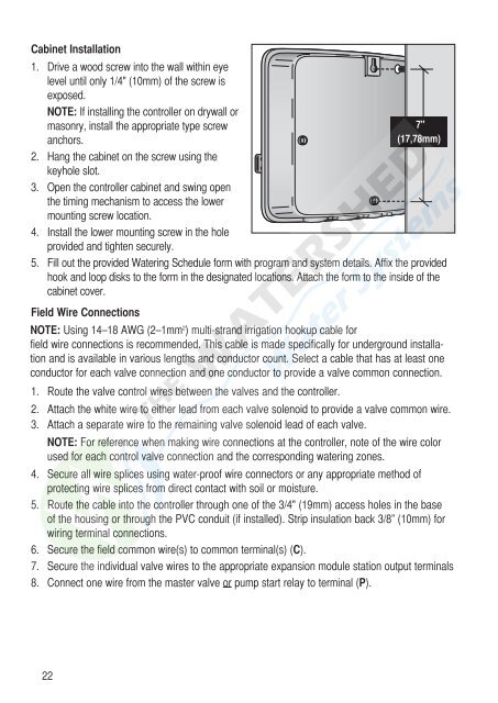
Cabinet Installation1. Drive a wood screw into the wall within eyelevel until only 1/4" (10mm) of the screw isexposed.NOTE: If installing the controller on drywall ormasonry, install the appropriate type screwanchors.2. Hang the cabinet on the screw using thekeyhole slot.3. Open the controller cabinet and swing openthe timing mechanism to access the lowermounting screw location.4. Install the lower mounting screw in the holeprovided and tighten securely.7"(17,78mm)5. Fill out the provided Watering Schedule form with program and system details. Affix the providedhook and loop disks to the form in the designated locations. Attach the form to the inside of thecabinet cover.Field Wire ConnectionsNOTE: Using 14–18 AWG (2–1mm 2 ) multi-strand irrigation hookup cable forfield wire connections is recommended. This cable is made specifically for underground installationand is available in various lengths and conductor count. Select a cable that has at least oneconductor for each valve connection and one conductor to provide a valve common connection.1. Route the valve control wires between the valves and the controller.2. Attach the white wire to either lead from each valve solenoid to provide a valve common wire.3. Attach a separate wire to the remaining valve solenoid lead of each valve.NOTE: For reference when making wire connections at the controller, note of the wire colorused for each control valve connection and the corresponding watering zones.4. Secure all wire splices using water-proof wire connectors or any appropriate method ofprotecting wire splices from direct contact with soil or moisture.5. Route the cable into the controller through one of the 3/4" (19mm) access holes in the baseof the housing or through the PVC conduit (if installed). Strip insulation back 3/8” (10mm) forwiring terminal connections.6. Secure the field common wire(s) to common terminal(s) (C).7. Secure the individual valve wires to the appropriate expansion module station output terminals8. Connect one wire from the master valve or pump start relay to terminal (P).22