Bedienungsanleitung - Ljudia
Bedienungsanleitung - Ljudia
Bedienungsanleitung - Ljudia

You also want an ePaper? Increase the reach of your titles
YUMPU automatically turns print PDFs into web optimized ePapers that Google loves.
InhaltsverzeichnisTable of contentsEINFÜHRUNG................................................................................................................................................... 3Lieferumfang .................................................................................................................................................. 3SICHERHEITSHINWEISE................................................................................................................................. 4BESTIMMUNGSGEMÄßE VERWENDUNG..................................................................................................... 6GERÄTEBESCHREIBUNG............................................................................................................................... 7Features ......................................................................................................................................................... 7Geräteübersicht.............................................................................................................................................. 7INBETRIEBNAHME .......................................................................................................................................... 8Montage ......................................................................................................................................................... 8Anschluss an den DMX-512 Controller / Verbindung Gerät - Gerät............................................................ 12Anschluss ans Netz...................................................................................................................................... 13BEDIENUNG ................................................................................................................................................... 13Stand Alone-Betrieb ..................................................................................................................................... 13DMX-gesteuerter Betrieb ............................................................................................................................. 13Adressierung des Geräts ............................................................................................................................. 13DMX-Protokoll .............................................................................................................................................. 15Control Board ............................................................................................................................................... 17Hauptfunktionen ........................................................................................................................................... 18Fehlermeldungen ......................................................................................................................................... 24REINIGUNG UND WARTUNG........................................................................................................................ 25Reinigung des Heizelements ....................................................................................................................... 25Sicherungswechsel ...................................................................................................................................... 26TECHNISCHE DATEN .................................................................................................................................... 27INTRODUCTION ............................................................................................................................................. 28Delivery includes .......................................................................................................................................... 28SAFETY INSTRUCTIONS............................................................................................................................... 29OPERATING DETERMINATIONS.................................................................................................................. 30DESCRIPTION OF THE DEVICE ................................................................................................................... 32Features ....................................................................................................................................................... 32Overview ...................................................................................................................................................... 32STARTING OPERATION................................................................................................................................ 33Installation .................................................................................................................................................... 33DMX-512 connection / connection between fixtures.................................................................................... 37Connection with the mains........................................................................................................................... 38OPERATION.................................................................................................................................................... 38Stand Alone operation.................................................................................................................................. 38DMX-controlled operation ............................................................................................................................ 38Addressing ................................................................................................................................................... 38DMX-protocol ............................................................................................................................................... 40Control Board ............................................................................................................................................... 42Main functions .............................................................................................................................................. 43Error Messages............................................................................................................................................ 49CLEANING AND MAINTENANCE ................................................................................................................. 49Cleaning the heating element ...................................................................................................................... 50Replacing the fuse ....................................................................................................................................... 50TECHNICAL SPECIFICATIONS..................................................................................................................... 51Diese <strong>Bedienungsanleitung</strong> gilt für die Artikelnummer 51843010This user manual is valid for the article number 51843010Das neueste Update dieser <strong>Bedienungsanleitung</strong> finden Sie im Internet unter:You can find the latest update of this user manual in the Internet under:www.futurelight.com2/5100024843.DOC, Version 1.1
BEDIENUNGSANLEITUNGPHF-1000Moving-Head-FoggerLesen Sie vor der ersten Inbetriebnahme zur eigenen Sicherheit diese <strong>Bedienungsanleitung</strong>sorgfältig durch!Alle Personen, die mit der Aufstellung, Inbetriebnahme, Bedienung, Wartung und Instandhaltung diesesGerätes zu tun haben, müssen- entsprechend qualifiziert sein- diese <strong>Bedienungsanleitung</strong> genau beachten- die <strong>Bedienungsanleitung</strong> als Teil des Produkts betrachten- die <strong>Bedienungsanleitung</strong> während der Lebensdauer des Produkts behalten- die <strong>Bedienungsanleitung</strong> an jeden nachfolgenden Besitzer oder Benutzer des Produkts weitergeben- sich die letzte Version der Anleitung im Internet herunter ladenEINFÜHRUNGWir freuen uns, dass Sie sich für einen FUTURELIGHT PHF-1000 entschieden haben. Wenn Sienachfolgende Hinweise beachten, sind wir sicher, dass Sie lange Zeit Freude an Ihrem Kauf haben werden.Nehmen Sie den PHF-1000 aus der Verpackung.Lieferumfang1 Gerät1 Fluid-Tank1 <strong>Bedienungsanleitung</strong>1 Kabel MC-50, 5m, schwarz,XLR m/f,symmetr. 3022050N2 FUTURELIGHT Omega Halter 180mm 518369833/5100024843.DOC, Version 1.1
SICHERHEITSHINWEISEACHTUNG!Seien Sie besonders vorsichtig beim Umgang mit gefährlicher Netzspannung. Bei dieserSpannung können Sie einen lebensgefährlichen elektrischen Schlag erhalten!Dieses Gerät hat das Werk in sicherheitstechnisch einwandfreiem Zustand verlassen. Um diesen Zustand zuerhalten und einen gefahrlosen Betrieb sicherzustellen, muss der Anwender die Sicherheitshinweise und dieWarnvermerke unbedingt beachten, die in dieser <strong>Bedienungsanleitung</strong> enthalten sind.Unbedingt lesen:Bei Schäden, die durch Nichtbeachtung der Anleitung verursacht werden, erlischt der Garantieanspruch.Für daraus resultierende Folgeschäden übernimmt der Hersteller keine Haftung.Das Gerät darf nicht in Betrieb genommen werden, nachdem es von einem kalten in einen warmen Raumgebracht wurde. Das dabei entstehende Kondenswasser kann unter Umständen Ihr Gerät zerstören. LassenSie das Gerät solange uneingeschaltet, bis es Zimmertemperatur erreicht hat!Bitte überprüfen Sie vor der ersten Inbetriebnahme, ob kein offensichtlicher Transportschaden vorliegt.Sollten Sie Schäden an der Netzleitung oder am Gehäuse entdecken, nehmen Sie das Gerät nicht in Betriebund setzen sich bitte mit Ihrem Fachhändler in Verbindung.Der Aufbau entspricht der Schutzklasse I. Der Netzstecker darf nur an eine Schutzkontakt-Steckdoseangeschlossen werden, deren Spannung und Frequenz mit dem Typenschild des Gerätes genauübereinstimmt. Ungeeignete Spannungen und ungeeignete Steckdosen können zur Zerstörung des Gerätesund zu tödlichen Stromschlägen führen.Den Netzstecker immer als letztes einstecken. Der Netzstecker muss dabei gewaltfrei eingesetzt werden.Achten Sie auf einen festen Sitz des Netzsteckers.Lassen Sie die Netzleitung nicht mit anderen Kabeln in Kontakt kommen! Seien Sie vorsichtig beim Umgangmit Netzleitungen und -anschlüssen. Fassen Sie diese Teile nie mit feuchten Händen an! Feuchte Händekönnen tödliche Stromschläge zu Folge haben.Netzleitungen nicht verändern, knicken, mechanisch belasten, durch Druck belasten, ziehen, erhitzen undnicht in die Nähe von Hitze- oder Kältequellen bringen. Bei Missachtung kann es zu Beschädigungen derNetzleitung, zu Brand oder zu tödlichen Stromschlägen kommen.Die Kabeleinführung oder die Kupplung am Gerät dürfen nicht durch Zug belastet werden. Es muss stetseine ausreichende Kabellänge zum Gerät hin vorhanden sein. Andernfalls kann das Kabel beschädigtwerden, was zu tödlichen Stromschlägen führen kann.Achten Sie darauf, dass die Netzleitung nicht gequetscht oder durch scharfe Kanten beschädigt werdenkann. Überprüfen Sie das Gerät und die Netzleitung in regelmäßigen Abständen auf Beschädigungen.Werden Verlängerungsleitungen verwendet muss sichergestellt werden, dass der Adernquerschnitt für diebenötigte Stromzufuhr des Gerätes zugelassen ist. Alle Warnhinweise für die Netzleitung gelten auch fürevtl. Verlängerungsleitungen.Gerät bei Nichtbenutzung und vor jeder Reinigung vom Netz trennen! Fassen Sie dazu den Netzstecker ander Griffläche an und ziehen Sie niemals an der Netzleitung! Ansonsten kann das Kabel und der Steckerbeschädigt werden was zu tödlichen Stromschlägen führen kann. Sind Stecker oder Geräteschalter, z. B.durch Einbau nicht erreichbar, so muss netzseitig eine allpolige Abschaltung vorgenommen werden.Wenn der Netzstecker oder das Gerät staubig ist, dann muss es außer Betrieb genommen werden, derStromkreis muss allpolig unterbrochen werden und das Gerät mit einem trockenen Tuch gereinigt werden.Staub kann die Isolation reduzieren, was zu tödlichen Stromschlägen führen kann. Stärkere Verschmutzungenim und am Gerät dürfen nur von einem Fachmann beseitigt werden.ACHTUNG! Vor Befüllen Netzstecker ziehen.4/5100024843.DOC, Version 1.1
Flüssigkeit niemals trinken, einnehmen oder äußerlich anwenden! Von Kindern fernhalten und unzugänglichaufbewahren. Bei Haut-/Augenkontakt mit viel Wasser ab- bzw. ausspülen (ggf. einen Arzt aufsuchen).EXPLOSIONSGEFAHR! Mischen Sie niemals entzündliche Flüssigkeiten jeglicher Art unter das Nebelfluid.Achten Sie darauf, dass das Gerät stets aufrecht installiert ist.Richten Sie die Nebelaustrittsdüse niemals direkt auf Personen oder auf offene Flammen.Richten Sie den Dampf niemals auf sich selbst, Personen oder Haustiere.Richten Sie den Dampf keinesfalls auf Steckdosen oder sonstige Teile unter Stromspannung. Sie könntendiese beschädigen oder sich gar selbst gefährlichen Elektroschlägen aussetzen.Richten Sie den Dampf niemals auf das Gerät selbst und nicht auf Oberflächen, die nicht hitzebeständigsind.Vermeiden Sie möglichst den direkten Hautkontakt mit Dampf. Die hohe Temperatur kann beiunsachgemäßer Anwendung Verbrennungen verursachen.VERBRENNUNGSGEFAHR! Mindestens 50 cm Abstand zur Düse einhalten!Bei Überkopfmontage (Montagehöhe >100 cm) ist das Gerät immer mit einem geeigneten Sicherheitsfangseilzu sichern.Je nach Höhe der Luftfeuchtigkeit und Raumtemperatur kann sich Kondensat im Bereich der Nebelaustrittsdüsebilden. Dieses Kondensat kann heiß sein und nach unten abtropfen. Der Aufstellort bzw. dieMontage des Nebelgerätes muss daher so erfolgen, dass abtropfendes Kondensat weder Personen- nochSachschaden an Böden, Oberflächen oder Textilien hervorrufen kann. Eine Montage darf nicht überPersonen erfolgen, da eventuell heißes, abtropfendes Kondensat zu Augen- und Hautverletzungen und aufKleidung zu Verunreinigungen führen kann. Auf glatten Böden kann abtropfendes Kondensat zu Rutschgefahrführen.Gerät bei Nichtbenutzung und vor jeder Reinigung vom Netz trennen! Fassen Sie dazu den Netzstecker ander Griffläche an und ziehen Sie niemals an der Netzleitung!Möchten Sie das Gerät längere Zeit nicht benutzen, entleeren Sie es komplett, bevor Sie es wegstellen.Es dürfen unter keinen Umständen Flüssigkeiten aller Art in Steckdosen, Steckverbindungen oder inirgendwelche Geräteöffnungen oder Geräteritzen eindringen. Besteht der Verdacht, dass - auch nurminimale - Flüssigkeit in das Gerät eingedrungen sein könnte, muss das Gerät sofort allpolig vom Netzgetrennt werden. Dies gilt auch, wenn das Gerät hoher Luftfeuchtigkeit ausgesetzt war. Auch wenn dasGerät scheinbar noch funktioniert, muss es von einen Fachmann überprüft werden ob durch denFlüssigkeitseintritt eventuell Isolationen beeinträchtigt wurden. Reduzierte Isolationen können tödlicheStromschläge hervorrufen.In das Gerät dürfen keine fremden Gegenstände gelangen. Dies gilt insbesondere für Metallteile. Solltenauch nur kleinste Metallteile wie Heft- und Büroklammern oder gröbere Metallspäne in das Gerät gelangen,so ist das Gerät sofort außer Betrieb zu nehmen und allpolig vom Netz zu trennen. Durch Metallteilehervorgerufene Fehlfunktionen und Kurzschlüsse können tödliche Verletzungen zur Folge haben.Bei der ersten Inbetriebnahme kann es zu Rauch- und Geruchserzeugung kommen. Hierbei handelt es sichnicht um eine Störung des Gerätes.Achtung: Gerät niemals während des Betriebes berühren. Gehäuse erhitzt sich!Kinder und Laien vom Gerät fern halten!Das Gerät darf niemals unbeaufsichtigt betrieben werden!Bewahren Sie das Gerät außerhalb der Reichweite von Kindern und Personen auf, die es ohne Aufsichtnicht betätigen können.5/5100024843.DOC, Version 1.1
BESTIMMUNGSGEMÄßE VERWENDUNGBei diesem Gerät handelt es sich um eine kopfbewegte Nebelmaschine zur Erzeugung von dichtem Nebelaus speziellem Nebelfluid. Dieses Produkt ist nur für den Anschluss an 230 V, 50 Hz Wechselspannungzugelassen und wurde ausschließlich zur Verwendung in Innenräumen konzipiert.Dieses Gerät ist für professionelle Anwendungen, z. B. auf Bühnen, in Diskotheken, Theatern etc.vorgesehen.Vermeiden Sie Erschütterungen und jegliche Gewaltanwendung bei der Installation oder Inbetriebnahme desGerätes.Das Gerät darf niemals am Gerätekopf angehoben werden, da ansonsten die Mechanik beschädigt werdenkönnte. Fassen Sie das Gerät immer an den Tragegriffen an.Achten Sie bei der Wahl des Installationsortes darauf, dass das Gerät nicht zu großer Hitze, Feuchtigkeitund Staub ausgesetzt wird. Vergewissern Sie sich, dass keine Kabel frei herumliegen. Bitte achten Siedarauf, dass das Gerät nicht berührt oder umgestoßen werden kann. Sie gefährden Ihre eigene und dieSicherheit Dritter!Vor Befüllen des Gerätes vom Netz trennen! Keine heißen Flüssigkeiten einfüllen!Nur Präparate mit schriftlicher Eignungsangabe für diesen Gerätetyp verwenden. Verwenden Sieausschließlich hochwertige und von Ihrem Händler empfohlene Nebelfluide auf Wasserbasis. Andere Nebelfluidekönnen zum Verstopfen oder Tropfen des Gerätes führen.Achten Sie unbedingt darauf, dass sich immer eine ausreichende Menge Nebelfluid im Tank befindet. DerBetrieb ohne Nebelfluid führt zu Pumpenschäden und zur Überhitzung des Heizelementes.Nehmen Sie das Gerät erst in Betrieb, nachdem Sie sich mit seinen Funktionen vertraut gemacht haben.Lassen Sie das Gerät nicht von Personen bedienen, die sich nicht mit dem Gerät auskennen. Wenn Gerätenicht mehr korrekt funktionieren, ist das meist das Ergebnis von unfachmännischer Bedienung!Gerät immer trocken lagern.Die Umgebungstemperatur muss zwischen -5° C und +45° C liegen. Halten Sie das Gerät von direkterSonneneinstrahlung (auch beim Transport in geschlossenen Wägen) und Heizkörpern fern.Die relative Luftfeuchte darf 50 % bei einer Umgebungstemperatur von 45° C nicht überschreiten.Dieses Gerät darf nur in einer Höhenlage zwischen -20 und 2000 m über NN betrieben werden.Verwenden Sie das Gerät nicht bei Gewitter. Überspannung könnte das Gerät zerstören. Das Gerät beiGewitter allpolig vom Netz trennen (Netzstecker ziehen).Achten Sie bei der Gerätemontage, beim Geräteabbau und bei der Durchführung von Servicearbeitendarauf, dass der Bereich unterhalb des Montageortes abgesperrt ist.Bei Überkopfmontage (Montagehöhe >100 cm) ist das Gerät immer mit einem geeigneten Sicherheitsfangseilzu sichern. Das Sicherheitsfangseil muss an den dafür vorgesehenen Befestigungspunkten eingehängtwerden. Das Fangseil darf niemals an den Transportgriffen eingehängt werden!Betreiben Sie das Gerät nur, nachdem Sie sich vergewissert haben, dass das Gehäuse fest verschlossen istund alle nötigen Schrauben fest angezogen wurden.Nehmen Sie das Gerät erst in Betrieb, nachdem Sie sich mit seinen Funktionen vertraut gemacht haben.Lassen Sie das Gerät nicht von Personen bedienen, die sich nicht mit dem Gerät auskennen. Wenn Gerätenicht mehr korrekt funktionieren, ist das meist das Ergebnis von unfachmännischer Bedienung!Soll das Gerät transportiert werden, verwenden Sie bitte die Originalverpackung, um Transportschäden zuvermeiden.6/5100024843.DOC, Version 1.1
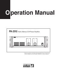
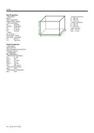
Beachten Sie bitte, dass eigenmächtige Veränderungen an dem Gerät aus Sicherheitsgründen verbotensind.Der Serienbarcode darf niemals vom Gerät entfernt werden, da ansonsten der Garantieanspruch erlischt.Wird das Gerät anders verwendet als in dieser <strong>Bedienungsanleitung</strong> beschrieben, kann dies zu Schäden amProdukt führen und der Garantieanspruch erlischt. Außerdem ist jede andere Verwendung mit Gefahren, wiez. B. Kurzschluss, Brand, elektrischem Schlag, Abstürzen etc. verbunden.GERÄTEBESCHREIBUNGFeaturesInnovative Moving-Head Nebelmaschine• Nebelmaschine mit kräftigem Nebelausstoß• Ideal für große Diskotheken oder große Bühnen• Leistungsstarker Ausstoß• Kein Spezialfluid notwendig• DMX-gesteuerter Betrieb oder Stand Alone Betrieb mit Master-/Slave-Funktion möglich• 5 oder 7 DMX-Kanäle wählbar für verschiedene Anwendungsmöglichkeiten• Timer-Funktion im 7 Kanal DMX-Modus• Anzahl der Szenen im Program Run kann beliebig verändert werden• Die Szenen im Program Run lassen sich über das Control Board oder externen Controller individuellanpassen und in den Speicher laden• 8 eingebaute Programme, die sich über den DMX-Controller aufrufen lassen• Musikgetaktet über eingebautes Mikrofon• Positionierung innerhalb 360° Pan und 265° Tilt• Control Board mit 4-stelligem Display und Folientastatur zur Einstellung der DMX-Startadresse, Pan-/Tilt-Reverse, Programm, Reset• DMX-512 Steuerung über jeden handelsüblichen DMX-Controller möglichGeräteübersicht(1) Gerätekopf(2) Nebelaustrittsdüse(3) Gerätearm(4) Base(5) Tragegriff(6) DMX-Ausgangsbuchse(7) DMX-Eingangsbuchse(8) Steuereinheit(9) Display(10) Mode/Enter-Taste(11) Down-Taste(12) Up-Taste(13) Exit-Taste(14) Kontroll-LED7/5100024843.DOC, Version 1.1
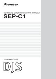
(15) Lüftergitter(16) Fluid-Tank(17) Fluidlevel-Anzeige(18) Netzanschluss(19) Sicherungshalter(20) Lüfter(21) Eingang für FluidschlauchINBETRIEBNAHMEStellen Sie das Gerät auf einer ebenen Fläche auf.Der Flüssigkeitsbehälter des Gerätes muss vor der Inbetriebnahme und stets im spannungslosen Zustandmit Fluid gefüllt werden (es könnte Fluid verschüttet werden).Bitte verwenden Sie nur Qualitäts-Nebelflüssigkeiten. Wir empfehlen hochwertige Eurolite Nebelfluide (z. B.Eurolite Smoke Fluid "P" Profi, 5 l) die Sie bei Ihrem Händler erhalten und bei denen eine Unbedenklichkeitsbescheinigunghinsichtlich Gesundheitsgefährdung vorliegt. Es dürfen keine Stoffe verwendet werden, die indie Klassifikation "gefährliche Arbeitsstoffe" oder "brennbare Flüssigkeiten" fallen.Sollte versehentlich Flüssigkeit in das Geräteinnere gelangen, so ist sofort der Netzstecker zu ziehen undein Fachmann zu konsultieren.MontageInstallieren Sie das Gerät an einem gut belüfteten Ort. Ein Betrieb in unzureichend belüfteten Räumen kannzur Kondensation des Nebelfluids führen. Die dabei entstehende rutschige Oberfläche kann zu Unfällenführen. Halten Sie einen Mindestabstand von 20 cm um und über dem Gerät ein.Desweiteren ist darauf zu achten, dass die Nebelaustrittsdüse nicht in Augenhöhe des Publikumsausgerichtet wird. Um einen guten Effekt zu erzielen, sollte der Abstand zum Publikum mindestens 1,5 mbetragen.8/5100024843.DOC, Version 1.1
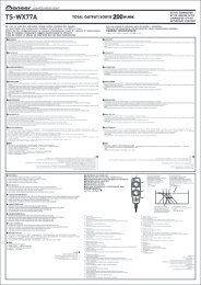
Achtung: Am letzten Gerät muss die DMX-Leitung durch einen Abschlusswiderstand abgeschlossenwerden. Dazu wird ein 120 Widerstand in einen XLR-Stecker zwischen Signal (–) und Signal (+) eingelötetund in den DMX-Ausgang am letzten Gerät gesteckt.Anschluss ans NetzSchließen Sie das Gerät über die beiliegende Netzanschlussleitung ans Netz an.Die Belegung der Anschlussleitungen ist wie folgt:Leitung Pin InternationalBraun Außenleiter LBlau Neutralleiter NGelb/Grün SchutzleiterDer Schutzleiter muss unbedingt angeschlossen werden!Wenn das Gerät direkt an das örtliche Stromnetz angeschlossen wird, muss eine Trennvorrichtung mitmindestens 3 mm Kontaktöffnung an jedem Pol in die festverlegte elektrische Installation eingebaut werden.Das Gerät darf nur an eine Elektroinstallation angeschlossen werden, die den VDE-BestimmungenDIN VDE 0100 entspricht. Die Hausinstallation muss mit einem Fehlerstromschutzschalter (RCD) mit 30 mABemessungsdifferenzstrom ausgestattet sein.BEDIENUNGWenn Sie das Gerät an die Spannungsversorgung angeschlossen haben, nimmt der PHF-1000 den Betriebauf. Während des Reset justieren sich die Motoren aus und das Gerät ist danach betriebsbereit.Nachdem das Gerät mit dem Aufheizen begonnen hat, leuchtet die Kontroll-LED rot. Ist das Gerät nach derAufheizzeit betriebsbereit, leuchtet die Kontroll-LED grün. Leuchtet die Kontroll-LED nicht, ist dasHeizelement ausgeschaltet.Stand Alone-BetriebDer PHF-1000 lässt sich im Stand Alone-Betrieb ohne Controller einsetzen.Trennen Sie dazu den PHF-1000 vom Controller und rufen Sie das vorprogrammierte Programm auf:1. Drücken Sie die Mode/Enter-Taste, um ins Hauptmenü "MODE" zu gelangen (Display blinkt).2. Drücken Sie die Mode/Enter-Taste und wählen Sie “RUN” durch Drücken der Up-Taste.3. Drücken Sie die Mode/Enter-Taste und wählen Sie “AUTO” durch Drücken der Up-Taste.4. Drücken Sie die Mode/Enter-Taste und wählen Sie “ALON” durch Drücken der Up-Taste.5. Drücken Sie die Mode/Enter-Taste zur Bestätigung.6. Drücken Sie 3 x Exit zur Bestätigung, auf dem Display erscheint “AU-A”.Bitte beachten Sie weitere Hinweise unter Control Board, Hauptfunktionen, Menüpunkte Mode und Edit.DMX-gesteuerter BetriebÜber Ihren DMX-Controller können Sie die einzelnen Geräte individuell ansteuern. Dabei hat jeder DMX-Kanal eine andere Belegung mit verschiedenen Eigenschaften. Die einzelnen DMX-Kanäle und ihreEigenschaften sind unter DMX-Protokoll aufgeführt.Adressierung des GerätsÜber das Control Board können Sie die DMX-Startadresse definieren. Die Startadresse ist der erste Kanal,auf den das Gerät auf Signale vom Controller reagiert.13/5100024843.DOC, Version 1.1
Wenn Sie die Startadresse z. B. auf 6 (8) definieren belegt das Gerät die Steuerkanäle 6 (8) bis 10 (14).Bitte vergewissern Sie sich, dass sich die Steuerkanäle nicht mit anderen Geräten überlappen, damit derPHF-1000 korrekt und unabhängig von anderen Geräten in der DMX-Kette funktioniert.Werden mehrere PHF-1000 auf eine Adresse definiert, arbeiten sie synchron.Drücken Sie die Up/Down-Tasten, um die gewünschte Startadresse einzustellen. Nun können Sie den PHF-1000 über Ihren Controller ansteuern.Bitte beachten Sie:Über das Display des Gerätes werden die Modi DMX-512 Daten und des Heizelementes angezeigt:1. Schalten Sie das Gerät ein. Das Gerät prüft, ob DMX-512 Daten empfangen werden oder nicht. WennDaten empfangen werden, erscheint „A.001“ mit der definierten Startadresse auf dem Display. Werdenkeine Daten empfangen, blinkt „A001“ mit der definierten Startadresse.Die Meldung erscheint-wenn kein 3-poliges XLR-Kabel (DMX Signalkabel vom Controller) in die DMX-Eingangsbuchse desGerätes gesteckt wurde.-wenn der Controller ausgeschaltet oder defekt ist.-das Kabel oder der Stecker defekt ist oder das Signalkabel nicht richtig eingesteckt ist.Achtung: Am letzten Gerät muss die DMX-Leitung durch einen 120 . Widerstand abgeschlossen werdendamit die Geräte korrekt funktionieren.2. Wenn das Heizelement angeschaltet ist, erscheint „A00.1“ mit der definierten Startadresse auf demDisplay. Wenn das Heizelement aus ist, erscheint „A001“ mit der definierten Startadresse auf dem Display.14/5100024843.DOC, Version 1.1
DMX-ProtokollBetriebsart 1 (5 DMX-Kanäle):Steuerkanal 1 - Horizontale Bewegung (Pan) (innerhalb 360°)Wenn Sie den Regler verschieben, bewegen Sie den Kopf horizontal (PAN).Allmähliches Einstellen des Kopfes bei langsamen Schieben des Reglers (0-255, 128-Mitte).Der Kopf kann an jeder gewünschten Einstellung angehalten werden.Steuerkanal 2 - Vertikale Bewegung (Tilt) (innerhalb 265°)Wenn Sie den Regler verschieben, bewegen Sie den Kopf vertikal (TILT).Allmähliches Einstellen des Kopfes bei langsamen Schieben des Reglers (0-255, 128-Mitte).Der Kopf kann an jeder gewünschten Einstellung angehalten werden.Steuerkanal 3 - Geschwindigkeit Pan-/Tilt-BewegungDecimal Hexad. Percentage S/F Eigenschaft0 255 00 FF 0% 100% F Abnehmende GeschwindigkeitSteuerkanal 4 - Pumpe an/ausDecimal Hexad. Percentage S/F Eigenschaft0 20 00 14 0% 8% S Pumpe aus (kein Nebel)21 255 15 FF 8% 100% S Pumpe an (Nebelausstoß)Steuerkanal 5 - Heizelement an/aus, Reset, interne ProgrammeDecimal Hexad. Percentage S/F Eigenschaft0 31 00 1F 0% 12% S Normaler Wechsel, Positionssuche über kürzesten Weg32 63 20 3F 13% 25% S Keine Funktion64 79 40 4F 25% 31% S Heizelement an80 95 50 5F 31% 37% S Reset96 111 60 6F 38% 44% S Internes Programm 1112 127 70 7F 44% 50% S Internes Programm 2128 143 80 8F 50% 56% S Internes Programm 3144 159 90 9F 56% 62% S Internes Programm 4160 175 A0 AF 63% 69% S Internes Programm 5176 191 B0 BF 69% 75% S Internes Programm 6192 207 C0 CF 75% 81% S Internes Programm 7208 223 D0 DF 82% 87% S Internes Programm 8224 239 E0 EF 88% 94% S Heizelement aus240 255 F0 FF 94% 100% S Keine FunktionBetriebsart 2 (7 DMX-Kanäle):Steuerkanal 1 - Horizontale Bewegung (Pan) (innerhalb 360°)Wenn Sie den Regler verschieben, bewegen Sie den Kopf horizontal (PAN).Allmähliches Einstellen des Kopfes bei langsamen Schieben des Reglers (0-255, 128-Mitte).Der Kopf kann an jeder gewünschten Einstellung angehalten werden.Steuerkanal 2 - Vertikale Bewegung (Tilt) (innerhalb 265°)Wenn Sie den Regler verschieben, bewegen Sie den Kopf vertikal (TILT).Allmähliches Einstellen des Kopfes bei langsamen Schieben des Reglers (0-255, 128-Mitte).Der Kopf kann an jeder gewünschten Einstellung angehalten werden.15/5100024843.DOC, Version 1.1
Steuerkanal 3 - Geschwindigkeit Pan-/Tilt-BewegungDecimal Hexad. Percentage S/F Eigenschaft0 255 00 FF 0% 100% F Abnehmende GeschwindigkeitSteuerkanal 4 - Pumpe an/ausDecimal Hexad. Percentage S/F Eigenschaft0 20 00 14 0% 8% S Pumpe aus (kein Nebel)21 254 15 FE 8% 100% S Pumpe an (Nebel) - abhängig von Steuerkanal 6 und 7255 255 FF FF 100% 100% S NebelausstoßSteuerkanal 5 - Heizelement an/aus, Reset, interne ProgrammeDecimal Hexad. Percentage S/F Eigenschaft0 31 00 1F 0% 12% S Normaler Wechsel, Positionssuche über kürzesten Weg32 63 20 3F 13% 25% S Keine Funktion64 79 40 4F 25% 31% S Heizelement an80 95 50 5F 31% 37% S Reset96 111 60 6F 38% 44% S Internes Programm 1112 127 70 7F 44% 50% S Internes Programm 2128 143 80 8F 50% 56% S Internes Programm 3144 159 90 9F 56% 62% S Internes Programm 4160 175 A0 AF 63% 69% S Internes Programm 5176 191 B0 BF 69% 75% S Internes Programm 6192 207 C0 CF 75% 81% S Internes Programm 7208 223 D0 DF 82% 87% S Internes Programm 8224 239 E0 EF 88% 94% S Heizelement aus240 255 F0 FF 94% 100% S Keine FunktionSteuerkanal 6 - Zeitintervall zwischen den NebelausstößenDieser Kanal ist nur aktiv wenn Kanal 4 auf 21-254 gestellt wurde.Decimal Hexad. Percentage S/F Eigenschaft0 3 00 03 0% 1% S Timer aus4 20 04 14 2% 8% S 20 Sek.21 255 15 FF 8% 100% S 21 - 255 Sek.Steuerkanal 7 - Nebeldauer jedes NebelausstoßesDieser Kanal ist nur aktiv wenn Kanal 4 auf 21-254 gestellt wurde.Decimal Hexad. Percentage S/F Eigenschaft0 3 00 03 0% % S Timer aus4 59 04 3B 2% 23% S 1 Sek.60 124 3C 7C 24% 49% S 5 Sek.125 189 7D BD 49% 74% S 10 Sek.190 255 BE FF 75% 100% S 15 Sek.16/5100024843.DOC, Version 1.1
Control BoardDas Control Board bietet mehrere Möglichkeiten: so lassen sich z. B. die DMX-Startadresse eingeben, dasHeizelement ein- und ausschalten, das vorprogrammierte Programm abspielen oder ein Reset durchführen.Drücken Sie die Mode/Enter-Taste, bis das Display zu blinken beginnt. Über die Up-Taste können Sie sichim Hauptmenü bewegen. Zur Auswahl des gewünschten Menüpunktes drücken Sie die Mode/Enter-Taste.Durch Drücken der Up/Down-Tasten können Sie die Auswahl verändern. Bestätigen Sie jede Änderung mitder Mode/Enter-Taste. Der jeweilige Modus kann durch die Exit-Taste verlassen werden. Die jeweiligenFunktionen werden im Folgenden beschrieben.Vorgabewerte grau unterlegt.Hauptmenü0 MODE1 HEAT2 SETUntermenü Erweiterungmenü Display FunktionVALU A001~AXXX Einstellen der DMX-StartadresseSLAV ON/OFF (SLAV) Slave-EinstellungADDRDMX-Adresse über externenEBOC ON/OFFController einstellenRUNAUTOALON (AU-A) Autom. Program Run im Stand AloneMAST (AU-M) Autom. Program Run als MasterSOUNALON (SO-A) Musikgesteuerter Program Run AloneMAST (SO-M) Musikgest. Program Run als MasterVALU D-XX ~ D-00 (DXXX) DMX-Wert anzeigenDISPRDIS ON/OFF Display-UmkehrungCLDI ON/OFF Display-AbschaltungOPEN ON/OFF HeizelementschaltungHTAU ON/OFF Heizelementschaltung/NetzschalterONLION/OFFHeizelementschaltung über externenControllerRPAN ON/OFF PAN-UmkehrungRTIL ON/OFF TILT-UmkehrungMIC M-XX Mikrofon-Empfindlichkeit einstellenAUTOON/OFFAutom. Program Run wenn kein DMX-SignalSOUNON/OFFMusikgest. Program Run wenn keinDMX-SignalMODE 5 CH/7 CH DMX-Modus einstellenRESTResetLODA ON/OFF Zurücksetzen auf WerkseinstellungenVER V-1.0~V-9.9 Software-Version3 ADJU TEST T–01 ~ T–XX Funktionstest der KanäleMATI 0000~9999 (Stund.) Betriebsstunden GerätHTRT 0000~9999 (Stund.) Betriebsstunden Heizelement4 TIME5 EDITCMRT ON/OFF Nur Service-FunktionCHRTON/OFFBetriebsstunden des HeizelementszurücksetzenSTEP S–01 ~ S–48 Anzahl der Steps im Run definierenREC RE-XX Autom. Speichern von Szenen01XX (00~FFH)Kanäle der einzelnen SzenenSC01 C01 ~ C3030XX (00~FFH)editieren~TIME (Sek.) T XXX (001~999) Step-Time einstellenSC48CNINON/OFFSzenen editieren via externenController17/5100024843.DOC, Version 1.1
Hauptfunktionen- Hauptmenü 0• Drücken Sie die Mode/Enter-Taste, um ins Hauptmenü "MODE" zu gelangen(Display blinkt).• Drücken Sie die Mode/Enter-Taste und wählen Sie "ADDR", “RUN” oder"DISP" durch Drücken der Up/Down-Tasten.• Drücken Sie die Mode/Enter-Taste zur Auswahl des gewünschten Untermenüs.- Einstellen der DMX-Startadresse, Slave-Einstellung- Einstellen der DMX-StartadresseMit dieser Funktion können Sie die DMX-Startadresse über das Control Board einstellen.• Wählen Sie “VALU” durch Drücken der Up/Down-Tasten.• Drücken Sie die Mode/Enter-Taste und stellen Sie die DMX-Adresse über die Up/Down-Tasten ein.• Drücken Sie die Mode/Enter-Taste zur Bestätigung.• Drücken Sie die Exit-Taste, um zum Hauptmenü zurückzukehren.- Slave-EinstellungMit dieser Funktion können Sie das Gerät als Slave-Gerät definieren.• Wählen Sie “SLAV” durch Drücken der Up/Down-Tasten.• Drücken Sie die Mode/Enter-Taste, auf dem Display erscheint “ON” oder “OFF”.• Drücken Sie die Up-Taste zur Auswahl von “ON” wenn Sie diese Funktion aktivieren möchten - oderdie Down-Taste zur Auswahl von “OFF” wenn nicht.• Drücken Sie die Mode/Enter-Taste zur Bestätigung.• Drücken Sie die Exit-Taste, um zum Hauptmenü zurückzukehren.- Einstellen der DMX-Startadresse über ControllerMit dieser Funktion können Sie die DMX-Startadresse über einen externen Controller einstellen.Diese Funktion kann nur aktiviert werden, wenn der DMX Wert von allen anderen Kanälen auf demController auf "0" gesetzt wird.• Wählen Sie “EBOC” durch Drücken der Up/Down-Tasten.• Drücken Sie die Mode/Enter-Taste, auf dem Display erscheint “ON” oder “OFF”.• Drücken Sie die Up-Taste zur Auswahl von “ON” wenn Sie diese Funktion aktivieren möchten - oderdie Down-Taste zur Auswahl von “OFF” wenn nicht.• Drücken Sie die Mode/Enter-Taste zur Bestätigung.• Drücken Sie die Exit-Taste, um zum Hauptmenü zurückzukehren.• Stellen Sie jetzt am Controller den DMX-Wert von Kanal 1 auf "7".• Stellen Sie den DMX-Wert von Kanal 2 auf "7" oder "8". In der Einstellung "7" können Sie dieStartadresse zwischen 1 und 255 einstellen. In der Einstellung "8" können Sie die Startadressezwischen 256 und 511 einstellen.• Stellen Sie den DMX-Wert von Kanal 3 auf die gewünschte Startadresse. Wenn Sie z. B. dieStartadresse 57 einstellen möchten, stellen Sie Kanal 1 auf "7", Kanal 2 auf "7" und Kanal 3 auf "57".Wenn Sie die Startadresse 420 einstellen möchten, stellen Sie Kanal 1 auf "7", Kanal 2 auf "8" undKanal 3 auf "164" (256+164=420).• Warten Sie ca. 20 Sekunden und das Gerät führt einen Reset durch. Danach ist die neueStartadresse eingestellt.18/5100024843.DOC, Version 1.1
Run - Programm aufrufen, Master-EinstellungMit der Funktion "RUN" lässt sich das interne Programm aufrufen. Die Anzahl der Steps können Sieunter Step festlegen. Die einzelnen Szenen können Sie unter Edit abändern. Die Szenen lassen sichentweder automatisch (AUTO), d.h. mit der eingestellten Step-Time oder musikgesteuert (SOUN)abspielen. Die Auswahl "ALON" bedeutet Stand Alone-Modus und "MAST", dass das Gerät als Master-Gerät definiert wird.• Wählen Sie "AUTO" oder "SOUN" durch Drücken der Up/Down-Tasten.• Drücken Sie die Mode/Enter-Taste zur Auswahl des gewünschten Erweiterungsmenüs.• Wählen Sie "ALON" oder "MAST" durch Drücken der Up/Down-Tasten.• Drücken Sie die Mode/Enter-Taste zur Bestätigung.• Drücken Sie die Exit-Taste, um zum Hauptmenü zurückzukehren.Disp - DMX-Wert anzeigen, Display-Umkehrung, Display-Abschaltung- DMX-Wert anzeigenMit dieser Funktion lässt sich der DMX-Wert der einzelnen Kanäle anzeigen.• Wählen Sie "VALU" durch Drücken der Up/Down-Tasten.• Drücken Sie die Mode/Enter-Taste zur Bestätigung; auf dem Display erscheint “D-00”. In dieserEinstellung wird jede Kanaländerung auf dem Display angezeigt.• Drücken Sie die Up-Taste, um den gewünschten Kanal auszuwählen: Wenn Sie z. B. “D-14”auswählen, erscheint auf dem Display nur der DMX-Wert des 14. Kanals.• Drücken Sie die Mode/Enter-Taste zur Bestätigung.• Auf dem Display erscheint "D-XX“, ”X” steht für den DMX-Wert des ausgewählten Kanals.• Drücken Sie die Mode/Enter-Taste zur Bestätigung.• Drücken Sie die Exit-Taste, um zum Hauptmenü zurückzukehren.rDis - Display-UmkehrungMit dieser Funktion lässt sich das Display um 180° drehen.• Wählen Sie "RDIS" durch Drücken der Up/Down-Tasten.• Drücken Sie die Mode/Enter-Taste, auf dem Display erscheint “ON” oder “OFF”.• Drücken Sie die Up-Taste zur Auswahl von “ON” wenn Sie diese Funktion aktivieren möchten (dasDisplay wird um 180° gedreht) - oder die Down-Taste zur Auswahl von “OFF” wenn nicht.• Drücken Sie die Mode/Enter-Taste zur Bestätigung.• Drücken Sie die Exit-Taste, um zum Hauptmenü zurückzukehren.- Display-AbschaltungMit dieser Funktion lässt sich das Display nach zwei Minuten abschalten.• Wählen Sie "CLDI" durch Drücken der Up/Down-Tasten.• Drücken Sie die Mode/Enter-Taste, auf dem Display erscheint “ON” oder “OFF”.• Drücken Sie die Up-Taste zur Auswahl von “ON” wenn Sie diese Funktion aktivieren möchten - oderdie Down-Taste zur Auswahl von “OFF” wenn nicht.• Drücken Sie die Mode/Enter-Taste zur Bestätigung.• Drücken Sie die Exit-Taste, um zum Hauptmenü zurückzukehren.19/5100024843.DOC, Version 1.1
- Hauptmenü 1• Drücken Sie die Mode/Enter-Taste, um ins Hauptmenü zu gelangen (Display blinkt).• Drücken Sie die Up/Down-Tasten zur Auswahl von “HEAT”.- HeizelementschaltungMit dieser Funktion lässt sich das Heizelement über das Control Board an- oder abschalten.• Wählen Sie "OPEN" durch Drücken der Up/Down-Tasten.• Drücken Sie die Mode/Enter-Taste, auf dem Display erscheint “ON” oder “OFF”.• Drücken Sie die Up/Down-Tasten zur Auswahl von “ON” um das Heizelement anzuschalten, oder“OFF” um sie abzuschalten.• Drücken Sie die Mode/Enter-Taste zur Bestätigung.• Drücken Sie die Exit-Taste, um zum Hauptmenü zurückzukehren.- Heizelementschaltung über NetzschalterMit dieser Funktion lässt sich das Heizelement über den Netzschalter an- oder abschalten.• Wählen Sie “HTAU” durch Drücken der Up/Down-Tasten.• Drücken Sie die Mode/Enter-Taste, auf dem Display erscheint “ON” oder “OFF”.• Drücken Sie die Up-Taste zur Auswahl von “ON” wenn Sie diese Funktion aktivieren möchten - oderdie Down-Taste zur Auswahl von “OFF” wenn nicht.• Drücken Sie die Mode/Enter-Taste zur Bestätigung.• Drücken Sie die Exit-Taste, um zum Hauptmenü zurückzukehren.- Heizelementschaltung über externen ControllerMit dieser Funktion lässt sich das Heizelement über den externen Controller an- oder abschalten.• Wählen Sie “ONLI” durch Drücken der Up/Down-Tasten.• Drücken Sie die Mode/Enter-Taste, auf dem Display erscheint “ON” oder “OFF”.• Drücken Sie die Up-Taste zur Auswahl von “ON” wenn Sie diese Funktion aktivieren möchten - oderdie Down-Taste zur Auswahl von “OFF” wenn nicht.• Drücken Sie die Mode/Enter-Taste zur Bestätigung.• Drücken Sie die Exit-Taste, um zum Hauptmenü zurückzukehren.- Hauptmenü 2• Drücken Sie die Mode/Enter-Taste, um ins Hauptmenü zu gelangen (Display blinkt).• Drücken Sie die Up/Down-Tasten zur Auswahl von “SET”.rpan - PAN-UmkehrungMit dieser Funktion lässt sich die PAN-Bewegung umkehren.• Wählen Sie “RPAN” durch Drücken der Up/Down-Tasten.• Drücken Sie die Mode/Enter-Taste, auf dem Display erscheint “ON” oder “OFF”.• Drücken Sie die Up-Taste zur Auswahl von “ON” wenn Sie diese Funktion aktivieren möchten - oderdie Down-Taste zur Auswahl von “OFF” wenn nicht.• Drücken Sie die Mode/Enter-Taste zur Bestätigung.• Drücken Sie die Exit-Taste, um zum Hauptmenü zurückzukehren.20/5100024843.DOC, Version 1.1
til - TILT-UmkehrungMit dieser Funktion lässt sich die TILT-Bewegung umkehren.• Wählen Sie “RTIL” durch Drücken der Up/Down-Tasten.• Drücken Sie die Mode/Enter-Taste, auf dem Display erscheint “ON” oder “OFF”.• Drücken Sie die Up-Taste zur Auswahl von “ON” wenn Sie diese Funktion aktivieren möchten - oderdie Down-Taste zur Auswahl von “OFF” wenn nicht.• Drücken Sie die Mode/Enter-Taste zur Bestätigung.• Drücken Sie die Exit-Taste, um zum Hauptmenü zurückzukehren.- MikrofonempfindlichkeitMit dieser Funktion lässt sich die Mikrofonempfindlichkeit zwischen 0 % und 99 % einstellen.• Wählen Sie "MIC" durch Drücken der Up/Down-Tasten.• Drücken Sie die Mode/Enter-Taste zur Bestätigung.• Drücken Sie die Up-Taste, um die gewünschte Empfindlichkeit einzustellen.• Drücken Sie die Mode/Enter-Taste zur Bestätigung.• Drücken Sie die Exit-Taste, um zum Hauptmenü zurückzukehren.- Automatischer Program Run wenn kein DMXMit dieser Funktion lässt sich das interne Programm aufrufen, wenn kein DMX-Signal empfangen wird.• Wählen Sie “AUTO” durch Drücken der Up/Down-Tasten.• Drücken Sie die Mode/Enter-Taste, auf dem Display erscheint “ON” oder “OFF”.• Drücken Sie die Up/Down-Tasten zur Auswahl von “ON” wenn Sie diese Funktion aktivieren möchten -oder die Down-Taste zur Auswahl von “OFF” wenn nicht.• Drücken Sie die Mode/Enter-Taste zur Bestätigung.• Drücken Sie die Exit-Taste, um zum Hauptmenü zurückzukehren.- Musiksteuerung wenn kein DMXMit dieser Funktion lässt sich das interne Programm musikgesteuert aufrufen, wenn kein DMX-Signalempfangen wird.• Wählen Sie “SOUN” durch Drücken der Up/Down-Tasten.• Drücken Sie die Mode/Enter-Taste, auf dem Display erscheint “ON” oder “OFF”.• Drücken Sie die Up/Down-Tasten zur Auswahl von “ON” wenn Sie diese Funktion aktivieren möchten -oder die Down-Taste zur Auswahl von “OFF” wenn nicht.• Drücken Sie die Mode/Enter-Taste zur Bestätigung.• Drücken Sie die Exit-Taste, um zum Hauptmenü zurückzukehren.- DMX-Modus einstellenMit dieser Funktion lässt sich der DMX-Modus einstellen.• Wählen Sie “MODE” durch Drücken der Up/Down-Tasten.• Drücken Sie die Mode/Enter-Taste, auf dem Display erscheint “5 CH”.• Drücken Sie die Up/Down-Taste, um "5 CH" oder "7 CH" auszuwählen.• Drücken Sie die Mode/Enter-Taste zur Bestätigung.• Drücken Sie die Exit-Taste, um zum Hauptmenü zurückzukehren.Rest - ResetMit dieser Funktion lässt sich über das Control Board ein Reset durchführen.• Wählen Sie “REST” durch Drücken der Up/Down-Tasten.• Drücken Sie die Mode/Enter-Taste zur Bestätigung.• Drücken Sie die Exit-Taste, um zum Hauptmenü zurückzukehren.- Zurücksetzen auf WerkseinstellungenMit dieser Funktion lässt sich das Gerät auf die Werkseinstellungen zurück setzen. Alle Einstellungenwerden auf Ihren Vorgabewert (grau unterlegt) zurück gesetzt. Evtl. abgespeicherte Szenen gehenverloren.• Wählen Sie “LODA” durch Drücken der Up/Down-Tasten.• Drücken Sie die Mode/Enter-Taste, auf dem Display erscheint “ON” oder “OFF”.• Drücken Sie die Up-Taste zur Auswahl von “ON” wenn Sie diese Funktion aktivieren möchten - oderdie Down-Taste zur Auswahl von “OFF” wenn nicht.• Drücken Sie die Mode/Enter-Taste zur Bestätigung.• Drücken Sie die Exit-Taste, um zum Hauptmenü zurückzukehren.21/5100024843.DOC, Version 1.1
Ver - Software-VersionMit dieser Funktion lässt sich die Software-Version des Gerätes auslesen.• Wählen Sie “VER” durch Drücken der Up/Down-Tasten.• Drücken Sie die Mode/Enter-Taste, auf dem Display erscheint “V-X.X”, “X.X“ steht für dieVersionsnummer,z. B. “V-1.0”. “V-2.6” etc.• Drücken Sie die Mode/Enter-Taste zur Bestätigung.• Drücken Sie die Exit-Taste, um zum Hauptmenü zurückzukehren.- Hauptmenü 3• Drücken Sie die Mode/Enter-Taste, um ins Hauptmenü zu gelangen (Display blinkt).• Drücken Sie die Up/Down-Tasten zur Auswahl von “ADJU”.- Funktionstest der einzelnen KanäleMit dieser Funktion lässt sich jeder einzelne Kanal auf seine (korrekte) Funktion überprüfen.• Wählen Sie “TESt” durch Drücken der Up/Down-Tasten.• Drücken Sie die Mode/Enter-Taste, auf dem Display erscheint “T-XX”, “X” steht für die Kanalnummer.Der aktuelle Kanal wird getestet.• Wählen Sie den gewünschten Kanal über die Up/Down-Tasten aus.• Drücken Sie die Mode/Enter-Taste zur Bestätigung.• Drücken Sie die Exit-Taste, um zum Hauptmenü zurückzukehren.- Hauptmenü 4• Drücken Sie die Mode/Enter-Taste, um ins Hauptmenü zu gelangen (Display blinkt).• Drücken Sie die Up/Down-Tasten zur Auswahl von “TIME”.- Betriebsstunden GerätMit dieser Funktion lassen sich die Betriebsstunden des Gerätes auslesen.• Wählen Sie “MATI” durch Drücken der Up/Down-Tasten.• Drücken Sie die Mode/Enter-Taste, auf dem Display erscheint “XXXX”, “X“ steht für die Anzahl derStunden.• Drücken Sie die Mode/Enter-Taste zur Bestätigung.• Drücken Sie die Exit-Taste, um zum Hauptmenü zurückzukehren.22/5100024843.DOC, Version 1.1
- Betriebsstunden HeizelementMit dieser Funktion lassen sich die Betriebsstunden des Heizelements auslesen.• Wählen Sie “HTRT” durch Drücken der Up/Down-Tasten.• Drücken Sie die Mode/Enter-Taste, auf dem Display erscheint “XXXX”, “X“ steht für die Anzahl derStunden.• Drücken Sie die Mode/Enter-Taste zur Bestätigung.• Drücken Sie die Exit-Taste, um zum Hauptmenü zurückzukehren.- Betriebsstunden des Heizelements zurücksetzenMit dieser Funktion lassen sich die Betriebsstunden des Heizelements zurücksetzen.• Wählen Sie “CHRT” durch Drücken der Up/Down-Tasten.• Drücken Sie die Mode/Enter-Taste, auf dem Display erscheint “ON” oder “OFF”.• Drücken Sie die Up-Taste zur Auswahl von “ON” wenn Sie diese Funktion aktivieren möchten - oderdie Down-Taste zur Auswahl von “OFF” wenn nicht.• Drücken Sie die Mode/Enter-Taste zur Bestätigung.• Drücken Sie die Exit-Taste, um zum Hauptmenü zurückzukehren.- Hauptmenü 5• Drücken Sie die Mode/Enter-Taste, um ins Hauptmenü zu gelangen (Display blinkt).• Drücken Sie die Up/Down-Tasten zur Auswahl von “EDIT”.- Anzahl der Steps im Run definierenMit dieser Funktion lässt sich die Anzahl der Stepsfestlegen die dann im Run aufgerufen werden.• Wählen Sie “STEP” durch Drücken der Up/Down-Tasten.• Drücken Sie die Mode/Enter-Taste, auf dem Displayerscheint “S-XX”, “XX” steht für die Gesamtzahl derabzuspeichernden Steps, so dass sich bis zu 48 Szenenin “RUN” abspielen lassen. Z. B. wenn “XX” 05 ist,bedeutet dies, dass im “RUN” die ersten 5 unter “EDIT”abgespeicherten Szenen aufgerufen werden.• Drücken Sie die Mode/Enter-Taste zum Speichern undVerlassen des Modus.- Szenen automatisch aufzeichnenMit dieser Funktion werden neue Szenen automatischaufgezeichnet.• Wählen Sie “REC” durch Drücken der Up/Down-Tasten.• Drücken Sie die Mode/Enter-Taste, auf dem Displayerscheint “RE-XX”, “XX” steht für die Gesamtzahl derabzuspeichernden Szenen, die sich in “RUN” abspielenlassen. Z. B. wenn “XX” 05 ist, bedeutet dies, dass im“RUN” die ersten 5 unter “EDIT” abgespeichertenSzenen aufgerufen werden.• Drücken Sie die Mode/Enter-Taste zum Speichern undVerlassen des Modus.- Kanäle der einzelnen Szenen editierenMit dieser Funktion lässt sich das Programm editieren,das dann in Run aufgerufen werden kann.a) Szenen editieren via Control Board• Wählen Sie “SC01” durch Drücken der Up/Down-Tasten.• Drücken Sie die Mode/Enter-Taste, auf dem Displayerscheint “SCXX”, “X” steht für die zu editierende Szenennummer.23/5100024843.DOC, Version 1.1
REINIGUNG UND WARTUNGDer Unternehmer hat dafür zu sorgen, dass sicherheitstechnische und maschinentechnische Einrichtungenmindestens alle vier Jahre durch einen Sachverständigen im Umfang der Abnahmeprüfung geprüft werden.Der Unternehmer hat dafür zu sorgen, dass sicherheitstechnische und maschinentechnische Einrichtungenmindestens einmal jährlich durch einen Sachkundigen geprüft werden.Dabei muss unter anderem auf folgende Punkte besonders geachtet werden:1) Alle Schrauben, mit denen das Gerät oder Geräteteile montiert sind, müssen fest sitzen und dürfen nichtkorrodiert sein.2) An Gehäuse, Befestigungen und Montageort (Decke, Abhängung, Traverse) dürfen keine Verformungensichtbar sein.3) Mechanisch bewegte Teile wie Achsen, Ösen u. Ä. dürfen keinerlei Verschleißspuren zeigen (z.B.Materialabrieb oder Beschädigungen) und dürfen sich nicht unwuchtig drehen.4) Die elektrischen Anschlussleitungen dürfen keinerlei Beschädigungen, Materialalterung (z.B. poröseLeitungen) oder Ablagerungen aufweisen. Weitere, auf den jeweiligen Einsatzort und die Nutzungabgestimmte Vorschriften werden vom sachkundigen Installateur beachtet und Sicherheitsmängelbehoben.LEBENSGEFAHR!Vor Wartungsarbeiten unbedingt allpolig vom Netz trennen!Das Gerät sollte regelmäßig von Verunreinigungen wie Staub usw. gereinigt werden. Verwenden Sie zurReinigung ein fusselfreies, angefeuchtetes Tuch. Auf keinen Fall Alkohol oder irgendwelche Lösungsmittelzur Reinigung verwenden!Den Lüfter monatlich reinigen.Schalten Sie das Gerät niemals ein, ohne vorher alle Abdeckungen geschlossen zu haben!Reinigen Sie das Innere des Geräts mindestens einmal im Jahr mit einem Staubsauger oder einerLuftbürste.Damit die Lager der rotierenden Teile gut funktionieren, müssen sie ca. alle 6 Monate geschmiert werden.Zum Ölen ist eine Spritze mit einer feinen Nadel zu benutzen. Die Ölmenge darf nicht übermäßig sein, um zuvermeiden, dass das Öl während des Rotierens ausläuft.Die Nebelaustrittsdüse sollte regelmäßig von Nebelfluidrückständen gereinigt werden.Reinigung des HeizelementsDas Heizelement sollte regelmäßig alle 30 Betriebsstunden gereinigt werden, um Ablagerungen zuvermeiden. Verwenden Sie dazu einen geeigneten Nebelmaschinenreiniger, der im Fachhandel erhältlich ist.Vorgehensweise:Nebelmaschine entleeren und den Reiniger im Lieferzustand in den Tank schütten. Anschließend an einemgut belüfteten Ort einige Male die Nebelfunktion der Maschine betätigen. Die Anzahl der benötigtenWiederholungen hängt vom Verschmutzungsgrad der Verdampfer-Elemente ab. Nach der Anwendung dieMaschine ganz entleeren, den restlichen Reiniger vollständig entnehmen und den Tank gut durchspülen.Die von uns empfohlenen EUROLITE Nebelfluide sind umwelttechnisch unbedenklich und können über denAbwasserkanal entsorgt werden.Im Geräteinneren befinden sich außer der Sicherung keine zu wartenden Teile. Wartungs- und Servicearbeitensind ausschließlich dem autorisierten Fachhandel vorbehalten!25/5100024843.DOC, Version 1.1
SicherungswechselWenn die Feinsicherung des Gerätes defekt ist, darf diese nur durch eine Sicherung gleichen Typs ersetztwerden.Vor dem Sicherungswechsel ist das Gerät allpolig von der Netzspannung zu trennen (Netzsteckerziehen).Vorgehensweise:Schritt 1: Öffnen Sie den Sicherungshalter an der Geräterückseite mit einem passendenSchraubendreher.Schritt 2: Entfernen Sie die defekte Sicherung aus dem Sicherungshalter.Schritt 3: Setzen Sie die neue Sicherung in den Sicherungshalter ein.Schritt 4: Setzen Sie den Sicherungshalter wieder im Gehäuse ein.Sollten einmal Ersatzteile benötigt werden, verwenden Sie bitte nur Originalersatzteile.Wenn die Anschlussleitung dieses Gerätes beschädigt wird, muss sie durch eine besondere Anschlussleitungersetzt werden, die von Ihrem Fachhändler erhältlich ist.Nach einem Defekt entsorgen Sie das unbrauchbar gewordene Gerät bitte gemäß den geltendengesetzlichen Vorschriften.Sollten Sie noch weitere Fragen haben, steht Ihnen Ihr Fachhändler jederzeit gerne zur Verfügung.26/5100024843.DOC, Version 1.1
TECHNISCHE DATENSpannungsversorgung: 230 V AC, 50 Hz ~Gesamtanschlusswert:1100 WDMX-Steuerkanäle: 5/7DMX 512-Anschluss:3-pol. XLRMax. Schwenkbewegung (Pan) 360°:in 2,0 sMax. Kippbewegung (Tilt) 265°:in 1,5 sAusstoßweite:ca. 5 mAufwärmzeit:ca. 5 min.Tankinhalt:ca. 1 lLänge der Grundfläche:580 mmBreite des Projektorarms:440 mmHöhe (Kopf horizontal):500 mmGewicht (netto):13 kgSicherung:T 6,3 A, 250 VZubehör:FUTURELIGHT EX-8/32 Controller Best.-Nr. 51834047FUTURELIGHT CP-240 Controller Best.-Nr. 51834265FUTURELIGHT CP-256/64 Controller 16bit Best.-Nr. 51834288FUTURELIGHT CP-512/64 Controller 16bit Best.-Nr. 51834295Wizard-512 USB DMX-Software + Interface Best.-Nr. 51860102Wizard-1024 USB DMX-Software + Interface Best.-Nr. 51860110FUTURELIGHT DES-3 Abschlusstecker 3-pol Best.-Nr. 51834001Nebelmaschinenreiniger, 1 Liter Best.-Nr. 51704592EUROLITE Smoke Fluid "E" Extrem, 5 Liter Best.-Nr. 51704325EUROLITE Smoke Fluid "B", 5 Liter Best.-Nr. 51704199EUROLITE Smoke Fluid "X" Extrem A2 5L Best.-Nr. 51704355EUROLITE Smoke Fluid "P" Profi, 5 Liter Best.-Nr. 51704210EUROLITE Smoke Fluid "P" Profi, 1 Liter Best.-Nr. 51704209EUROLITE Smoke Fluid "C" Standard, 5 Lit. Best.-Nr. 51704203Nebelfluid Duftstoff, 20ml, Tutti-Frutti Best.-Nr. 51704715Nebelfluid Duftstoff, 20ml, 'Caipirinha' Best.-Nr. 51704765Nebelfluid Duftstoff, 20ml, Pfirsich Best.-Nr. 51704770Nebelfluid Duftstoff, 20ml, 'Cola' Best.-Nr. 51704775Nebelfluid Duftstoff, 20ml, Himbeer Best.-Nr. 51704780Nebelfluid Duftstoff, 20ml, Vanille Best.-Nr. 51704720Nebelfluid Duftstoff, 20ml, Minze Best.-Nr. 51704700Nebelfluid Duftstoff, 20ml, Apfel Best.-Nr. 51704725Nebelfluid Duftstoff, 20ml, Limette Best.-Nr. 51704695Nebelfluid Duftstoff, 20ml, Kokos Best.-Nr. 51704740Nebelfluid Duftstoff, 20ml, Kirsch Best.-Nr. 51704710Nebelfluid Duftstoff, 20ml, 'Pina-Colada' Best.-Nr. 51704760Nebelfluid Duftstoff, 20ml, 'Disco' Best.-Nr. 51704755Nebelfluid Duftstoff, 20ml, Erdbeer Best.-Nr. 51704705Duftstoffset je 1x alle 14 Duftnoten Best.-Nr. 51704655Bitte beachten Sie: Technische Änderungen ohne vorherige Ankündigung und Irrtum vorbehalten.07.12.2007 ©27/5100024843.DOC, Version 1.1
USER MANUALPHF-1000Moving-Head-FoggerCAUTION!Keep this device away from rain and moisture!Unplug mains lead before opening the housing!For your own safety, please read this user manual carefully before you initially start-up.Every person involved with the installation, operation and maintenance of this device has to- be qualified- follow the instructions of this manual- consider this manual to be part of the total product- keep this manual for the entire service life of the product- pass this manual on to every further owner or user of the product- download the latest version of the user manual from the InternetINTRODUCTIONThank you for having chosen a FUTURELIGHT PHF-1000. If you follow the instructions given in this manual,we are sure that you will enjoy this device for a long period of time.Unpack your PHF-1000.Delivery includes1 Device1 Fluid tank1 User manual1 Cable MC-50, 5m, black, XLR m/f,balanced 3022050N2 FUTURELIGHT omega holder 180mm 5183698328/5100024843.DOC, Version 1.1
SAFETY INSTRUCTIONSCAUTION!Be careful with your operations. With a dangerous voltage you can suffer a dangerouselectric shock when touching the wires!This device has left our premises in absolutely perfect condition. In order to maintain this condition and toensure a safe operation, it is absolutely necessary for the user to follow the safety instructions and warningnotes written in this user manual.Important:Damages caused by the disregard of this user manual are not subject to warranty. The dealerwill not accept liability for any resulting defects or problems.If the device has been exposed to drastic temperature fluctuation (e.g. after transportation), do not switch iton immediately. The arising condensation water might damage your device. Leave the device switched offuntil it has reached room temperature.Please make sure that there are no obvious transport damages. Should you notice any damages on the A/Cconnection cable or on the casing, do not take the device into operation and immediately consult your localdealer.This device falls under protection-class I. The power plug must only be plugged into a protection class Ioutlet. The voltage and frequency must exactly be the same as stated on the device. Wrong voltages orpower outlets can lead to the destruction of the device and to mortal electrical shock.Always plug in the power plug last. The power plug must always be inserted without force. Make sure thatthe plug is tightly connected with the outlet.Never let the power-cord come into contact with other cables! Handle the power-cord and all connectionswith the mains with particular caution! Never touch them with wet hands, as this could lead to mortalelectrical shock.Never modify, bend, strain mechanically, put pressure on, pull or heat up the power cord. Never operate nextto sources of heat or cold. Disregard can lead to power cord damages, fire or mortal electrical shock.The cable insert or the female part in the device must never be strained. There must always be sufficientcable to the device. Otherwise, the cable may be damaged which may lead to mortal damage.Make sure that the power-cord is never crimped or damaged by sharp edges. Check the device and thepower-cord from time to time.If extension cords are used, make sure that the core diameter is sufficient for the required powerconsumption of the device. All warnings concerning the power cords are also valid for possible extensioncords.Always disconnect from the mains, when the device is not in use or before cleaning it. Only handle thepower-cord by the plug. Never pull out the plug by tugging the power-cord. Otherwise, the cable or plug canbe damaged leading to mortal electrical shock. If the power plug or the power switch is not accessible, thedevice must be disconnected via the mains.If the power plug or the device is dusty, the device must be taken out of operation, disconnected and then becleaned with a dry cloth. Dust can reduce the insulation which may lead to mortal electrical shock. Moresevere dirt in and at the device should only be removed by a specialist.CAUTION! Before filling the machine disconnect from mains.Never drink fluid or use it on the inside or outside of a human body. If fluid gets in contact with skin or eyes,rinse thoroughly with water. If it is necessary call a doctor immediately!29/5100024843.DOC, Version 1.1
DANGER OF EXPLOSION! Never add flammable liquids of any kind to the fog liquid.Keep device upright.Never aim the output nozzle directly at people or at open flames.Never aim the smoke at yourself, people or pets.Never aim the smoke at power sockets or other objects that are powered by electrical current. You coulddamage them or even expose yourself to hazardous electric shocks.Never aim the smoke at the device itself or at surfaces that are not heat resistant.Avoid direct skin contact with the smoke. Inappropriate use may cause burns due to high temperatures.DANGER OF BURNING! Keep minimum distance of 50 cm to nozzle!For overhead use (mounting height >100 cm), always fix the fixture with an appropriate safety-rope.Depending on the humidity and room temperature, condensed water may appear around the nozzle. Thecondensate can be hot and may drop down. This is why the installation place must be chosen in a way thatthe dropping condensate cannot harm persons or damage floors, surfaces or textiles.This device must never be installed over persons, because dropping condensate may cause eye and skininjury and harm textiles. Dropping condensate may cause danger of slippery on floors.Always disconnect from the mains, when the device is not in use or before cleaning it. Only handle thepower-cord by the plug. Never pull out the plug by tugging the power-cord.When the fog machine is not in use for a longer period of time empty the entire smoke fluid from the machinebefore storing it.There must never enter any liquid into power outlets, extension cords or any holes in the housing of thedevice. If you suppose that also a minimal amount of liquid may have entered the device, it must immediatelybe disconnected. This is also valid, if the device was exposed to high humidity. Also if the device is stillrunning, the device must be checked by a specialist if the liquid has reduced any insulation. Reducedinsulation can cause mortal electrical shock.There must never be any objects entering into the device. This is especially valid for metal parts. If any metalparts like staples or coarse metal chips enter into the device, the device must be taken out of operation anddisconnected immediately. Malfunction or short-circuits caused by metal parts may cause mortal injuries.During the initial start-up some smoke or smell may arise. This is a normal process and does not necessarilymean that the device is defective.Caution: During the operation, the housing becomes very hot.Keep away children and amateurs!Never leave this device running unattended.Store this device out of reach of children and amateurs who may not operate the device without supervision.OPERATING DETERMINATIONSThis device is a moving-head smoke-machine for creating a thick smoke made of a special smoke fluid. Thisproduct is only allowed to be operated with an alternating current of 230 V, 50 Hz and was designed forindoor use only.This device is designed for professional use, e.g. on stages, in discotheques, theatres etc.30/5100024843.DOC, Version 1.1
Do not shake the device. Avoid brute force when installing or operating the device.Never lift the fixture by holding it at the device head, as the mechanics may be damaged. Always hold thefixture at the transport handles.When choosing the installation-spot, please make sure that the device is not exposed to extreme heat,moisture or dust. There should not be any cables lying around. Please make sure that the unit cannot betouched or bumped. You endanger your own and the safety of others!Before filling the device disconnect from mains. Never fill in any hot liquids.Only use high-quality, water-based smoke fluid recommended by the manufacturer. Other smoke fluids maycause clogging.Always make sure there is sufficient smoke fluid in the fluid tank. Operating this smoke-machine withoutsmoke fluid will cause damage to the pump as well as over-heating of the heater.Operate the device only after having familiarized with its functions. Do not permit operation by persons notqualified for operating the device. Most damages are the result of unprofessional operation!Always store the device dry!Always drain the tank and please use the original packaging if the device is to be transported.The ambient temperature must always be between -5° C and +45° C. Keep away from direct insulation(particularly in cars) and heaters.The relative humidity must not exceed 50 % with an ambient temperature of 45° C.This device must only be operated in an altitude between -20 and 2000 m over NN.Never use the device during thunderstorms. Over voltage could destroy the device. Always disconnect thedevice during thunderstorms.Make sure that the area below the installation place is blocked when rigging, derigging or servicing thefixture.For overhead use (mounting height >100 cm), always fix the fixture with an appropriate safety-rope. Fix thesafety-rope at the correct fixation points only. The safety-rope must never be fixed at the transport handles!Only operate the fixture after having checked that the housing is firmly closed and all screws are tightlyfastened.Operate the device only after having become familiarized with its functions. Do not permit operation bypersons not qualified for operating the device. Most damages are the result of unprofessional operation!Please use the original packaging if the device is to be transported.Please consider that unauthorized modifications on the device are forbidden due to safety reasons!Never remove the serial barcode from the device as this would make the guarantee void.If this device will be operated in any way different to the one described in this manual, the product may sufferdamages and the guarantee becomes void. Furthermore, any other operation may lead to dangers like shortcircuit,burns, electric shock, crash etc.31/5100024843.DOC, Version 1.1
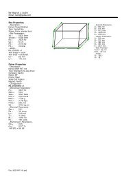
DESCRIPTION OF THE DEVICEFeaturesInnovative Moving-Head smoke-machine• Smoke-machine with powerful smoke output• Ideal for large discotheques or large stages• Powerful output• No need for special fluid• DMX-controlled operation or stand alone operation with Master/Slave-function• 5 or 7 DMX channels selectable for numerous applications• Timer-function in 7 channel mode• Number of scenes in Program Run can be changed individually• The scenes in Program Run can be modified via the Control Board or via an external controller and loadedinto the memory• 8 built-in programs can be called up via DMX-controller• Sound-controlled via built-in microphone• Positioning within 360° Pan and 265° Tilt• Control-Board with 4-digit display and foil-keyboard for adjusting the DMX-starting address, Pan/Tilt-Reverse, Program, Reset• DMX-control via every standard DMX-controllerOverview(1) Device head(2) Escape nozzle(3) Yoke(4) Base(5) Carrying handle(6) DMX-Out socket(7) DMX-In socket(8) Control Board(9) Display(10) Mode/Enter-button(11) Down-button(12) Up-button(13) Exit-button(14) Control LED32/5100024843.DOC, Version 1.1
(15) Ventilation grille(16) Fluid tank(17) Fluid level display(18) Power supply(19) Fuseholder(20) Ventilation fan(21) Fluid-tube inputSTARTING OPERATIONInstall the device on a plane surface.The fluid tank of the device needs to be filled with smoke fluid before starting up operation and alwaysdisconnected from the mains as fluid could be spilled.Only use quality smoke fluids available at your dealer. We recommend high-quality Eurolite smoke fluids (e.g. Eurolite Smoke Fluid "P" professional, 5 l). You must not use substances that are classified as "dangerousworking material" or "inflammable fluids".If fluid should get into the interior of the device, disconnect from mains immediately and consult a technician.InstallationInstall the device in a well-ventilated area. The operation in an unsufficiently ventilated room can lead to acondensation of the smoke fluid. The resulting slippery surface can cause accidents. Keep a minimumdistance of 20 cm around and above the device.Furthermore do not orientate the escape nozzle directly in the direction of the audience's eyes. In order tocreate a good effect, there should be a distance between the device and the audience of at least 1.5 m.33/5100024843.DOC, Version 1.1
Only install the smoke-machine on fire-resistant, scratch-resistant and water-resistant surfaces.Depending on the humidity and room temperature, condensed water may appear around the nozzle. Thecondensate can be hot and may drop down. This is why the installation place must be chosen in a way thatthe dropping condensate cannot harm persons or damage floors, surfaces or textiles.This device must never be installed over persons, because dropping condensate may cause eye and skininjury and harm textiles. Dropping condensate may cause danger of slippery on floors.This device is constructed for a standing or hanging installation. If the device is to be installed overhead, thefollowing safety instructions are binding:DANGER TO LIFE!Please consider the EN 60335-1:1996 and the respective national norms during theinstallation! The installation must only be carried out by an authorized dealer!The installation of the device has to be built and constructed in a way that it can hold 10 times the weight for1 hour without any harming deformation.The installation must always be secured with a secondary safety attachment, e.g. an appropriate catch net.This secondary safety attachment must be constructed in a way that no part of the installation can fall downif the main attachment fails.Procedure:The device should be installed outside areas where persons may walk by or be seated.When rigging, derigging or servicing thefixture staying in the area below theinstallation place, on bridges, under highworking places and other endangeredareas is forbidden.The operator has to make sure thatsafety-relating and machine-technicalinstallations are approved by an expertbefore taking into operation for the firsttime and after changes before taking intooperation another time.The operator has to make sure thatsafety-relating and machine-technicalinstallations are approved by an expertafter every four year in the course of anacceptance test.The operator has to make sure thatsafety-relating and machine-technicalinstallations are approved by a skilledperson once a year.IMPORTANT! OVERHEAD RIGGING REQUIRES EXTENSIVE EXPERIENCE, including (but not limited to)calculating working load limits, installation material being used, and periodic safety inspection of allinstallation material and the device. If you lack these qualifications, do not attempt the installation yourself,but instead use a professional structural rigger. Improper installation can result in bodily injury and.ordamage to property.The device has to be installed out of the reach of people.If the device shall be lowered from the ceiling or high joists, professional trussing systems have to be used.The device must never be fixed swinging freely in the room.34/5100024843.DOC, Version 1.1
Caution: Devices may cause severe injuries when crashing down! If you have doubts concerning the safetyof a possible installation, do NOT install the device!Before rigging make sure that the installation area can hold a minimum point load of 10 times the devicesweight.CAUTION!Use 2 appropriate clamps to rig the fixture on the truss.Follow the instructions mentioned at the bottom of the base.Make sure that the device is fixed properly! Ensure thatthe structure (truss) to which you are attaching the fixtures is secure.The Moving-Head-Fogger can be placed directly on the stage floor or rigged in any orientation on a trusswithout altering its operation characteristics (see the drawing).CAUTION!Always make sure that the tank capis always up!The fixture’s base enables to be mounted in two ways.For overhead use (mounting height >100 cm), always install an appropriate safety bond.You must only use safety bonds complying with DIN 56927, quick links complying with DIN 56926, shacklescomplying with DIN EN 1677-1 and BGV C1 carbines. The safety bonds, quick links, shackles and thecarbines must be sufficiently dimensioned and used correctly in accordance with the latest industrial safetyregulations (e. g. BGV C1, BGI 810-3).Please note: for overhead rigging in public or industrial areas, a series of safety instructions have to befollowed that this manual can only give in part. The operator must therefore inform himself on the currentsafety instructions and consider them.The manufacturer cannot be made liable for damages caused by incorrect installations or insufficient safetyprecautions!Install the safety bond by inserting the quick link in the hole on the bottom of the base Pull the safety bondover the trussing system etc. Insert the end in the quick link and tighten the fixation screw.The maximum drop distance must never exceed 20 cm.A safety bond which already hold the strain of a crash or which is defective must not be used again.DANGER TO LIFE!Before taking into operation for the first time, the installation has to be approved by an expert!35/5100024843.DOC, Version 1.1
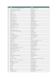
(1) Omega-holders(2) Clamp(3) Safety-rope(4) Quick-lock fastenerScrew one clamp each via a M12 screw and nut onto the Omega-clamps.Insert the quick-lock fasteners of the first Omega-clamp into the respectiveholes on the bottom of the device. Tighten the quick-lock fasteners fullyclockwise. Install the second Omega-clamp.36/5100024843.DOC, Version 1.1
DMX-512 connection / connection between fixturesThe wires must not come into contact with each other, otherwisethe fixtures will not work at all, or will not work properly.Please note, the starting address depends upon which controller is being used.Only use a stereo shielded cable and 3-pin XLR-plugs and connectors in order to connect the controller withthe fixture or one fixture with another.Occupation of the XLR-connection:If you are using controllers with this occupation, you can connect the DMX-output of the controller directlywith the DMX-input of the first fixture in the DMX-chain. If you wish to connect DMX-controllers with otherXLR-outputs, you need to use adapter-cables.Building a serial DMX-chain:Connect the DMX-output of the first fixture in the DMX-chain with the DMX-input of the next fixture. Alwaysconnect one output with the input of the next fixture until all fixtures are connected.Caution: At the last fixture, the DMX-cable has to be terminated with a terminator. Solder a 120 resistorbetween Signal (–) and Signal (+) into a 3-pin XLR-plug and plug it in the DMX-output of the last fixture.37/5100024843.DOC, Version 1.1
Connection with the mainsConnect the device to the mains with the enclosed power supply cable.The occupation of the connection-cables is as follows:Cable Pin InternationalBrown Live LBlue Neutral NYellow/Green EarthThe earth has to be connected!If the device will be directly connected with the local power supply network, a disconnection switch with aminimum opening of 3 mm at every pole has to be included in the permanent electrical installation.The device must only be connected with an electric installation carried out in compliance with the IECstandards.The electric installation must be equipped with a Residual Current Device (RCD) with a maximumfault current of 30 mA.OPERATIONAfter you connected the effect to the mains, the PHF-1000 starts running. During the Reset, the motors aretrimmed and the device is ready for use afterwards.After the machine starts heating up, the control LED lights up red. When the machine is ready for fogging,the control LED lights up green. If the control LED does not light up, the heating element is off.Stand Alone operationIn the Stand Alone mode, the PHF-1000 can be used without controller.Disconnect the PHF-1000 from the controller and call the internal program.1. Press [MODE/ENTER] button to enter the main menu "MODE" (display flashing)2. Press [MODE/ENTER] and select “RUN” by pressing [UP] button.3. Press [MODE/ENTER] and select “AUTO” by pressing [UP] button.4. Press [MODE/ENTER] and select “ALONE” by pressing [UP] button.5. Press [MODE/ENTER] to confirm.6. Press 3 x [EXIT] to confirm, the display shows “AU-A”.Please refer to the instructions under Control Board, Main functions, menus Run and Edit.DMX-controlled operationYou can control the devices individually via your DMX-controller. Every DMX-channel has a differentoccupation with different features. The individual channels and their features are listed under DMX-protocol.AddressingThe Control Board allows you to assign the DMX starting address, which is defined as the first channel fromwhich the PHF-1000 will respond to the controller.If you set, for example, the address to channel 6 (8), the PHF-1000 will use the channel 6 (8) to 10 (14) forcontrol.Please, be sure that you don’t have any overlapping channels in order to control each PHF-1000 correctlyand independently from any other fixture on the DMX-chain.If several PHF-1000 are addressed similarly, they will work synchronically.38/5100024843.DOC, Version 1.1
Press the Up/Down-buttons for setting the desired starting address. Now you can start operating the PHF-1000 via your lighting controller.Note:The modes of DMX 512 data and heating element are shown via the display:1. After switching on, the device will automatically detect whether DMX 512 data is received or not. If thedata is received, the display will show "A.001" with the actually set address. If there is no data received atthe DMX-input, the display will flash "A001" with the actually set address.This situation can occur if:- the 3 PIN XLR plug (cable with DMX signal from controller) is not connected with the input of the device.- the controller is switched off or defective, if the cable or connector is defective or the signal wires are swapin the input connector.Note:It’s necessary to insert the XLR termination plug (with 120 Ohm) in the last lighting in the link in order toensure proper transmission on the DMX data link.2. If the heating element is on, the the display will show "A00.1" with the actually set address. If the heatingelement is off, the the display will show "A001" with the actually set address.39/5100024843.DOC, Version 1.1
DMX-protocolOperating mode 1 (5 DMX channels):Control-channel 1 - Horizontal movement (Pan) (within 360°)Push slider up in order to move the head horizontally (PAN).Gradual head adjustment from one end of the slider to the other (0-255, 128-center).The head can be stopped at any position you wish.Control-channel 2 - Vertical movement (Tilt) (within 265°)Push slider up in order to move the head vertically (TILT).Gradual head adjustment from one end of the slider to the other (0-255, 128-center).The head can be stopped at any position you wish.Control-channel 3 - Pan/Tilt-speedDecimal Hexad. Percentage S/F Feature0 255 00 FF 0% 100% F Decreasing speedControl-channel 4 - Pump on/offDecimal Hexad. Percentage S/F Feature0 20 00 14 0% 8% S Pump off (no fogging)21 255 15 FF 8% 100% S Pump on (smoke-output)Control-channel 5 - Heating element on/off , Reset, internal programsDecimal Hexad. Percentage S/F Feature0 31 00 1F 0% 12% S Normal change, search position via shortest distance32 63 20 3F 13% 25% S No function64 79 40 4F 25% 31% S Heating element on80 95 50 5F 31% 37% S Reset96 111 60 6F 38% 44% S Internal program 1112 127 70 7F 44% 50% S Internal program 2128 143 80 8F 50% 56% S Internal program 3144 159 90 9F 56% 62% S Internal program 4160 175 A0 AF 63% 69% S Internal program 5176 191 B0 BF 69% 75% S Internal program 6192 207 C0 CF 75% 81% S Internal program 7208 223 D0 DF 82% 87% S Internal program 8224 239 E0 EF 88% 94% S Heating element off240 255 F0 FF 94% 100% S No functionOperating mode 2 (7 DMX channels):Control-channel 1 - Horizontal movement (Pan) (within 360°)Push slider up in order to move the head horizontally (PAN).Gradual head adjustment from one end of the slider to the other (0-255, 128-center).The head can be stopped at any position you wish.Control-channel 2 - Vertical movement (Tilt) (within 265°)Push slider up in order to move the head vertically (TILT).Gradual head adjustment from one end of the slider to the other (0-255, 128-center).The head can be stopped at any position you wish.40/5100024843.DOC, Version 1.1
Control-channel 3 - Pan/Tilt-speedDecimal Hexad. Percentage S/F Feature0 255 00 FF 0% 100% F Decreasing speedControl-channel 4 - Pump on/offDecimal Hexad. Percentage S/F Feature0 20 00 14 0% 8% S Pump off (no fogging)21 254 15 FE 8% 100% S Pump on (fogging) - depending on control-channel 6 and 7255 255 FF FF 100% 100% S Smoke-outputControl-channel 5 - Heating element on/off , Reset, internal programsDecimal Hexad. Percentage S/F Feature0 31 00 1F 0% 12% S Normal change, search position via shortest distance32 63 20 3F 13% 25% S No function64 79 40 4F 25% 31% S Heating element on80 95 50 5F 31% 37% S Reset96 111 60 6F 38% 44% S Internal program 1112 127 70 7F 44% 50% S Internal program 2128 143 80 8F 50% 56% S Internal program 3144 159 90 9F 56% 62% S Internal program 4160 175 A0 AF 63% 69% S Internal program 5176 191 B0 BF 69% 75% S Internal program 6192 207 C0 CF 75% 81% S Internal program 7208 223 D0 DF 82% 87% S Internal program 8224 239 E0 EF 88% 94% S Heating element off240 255 F0 FF 94% 100% S No functionControl-channel 6 - Interval between each fog emissionThis channel is only active if channel 4 is set to 21-254.Decimal Hexad. Percentage S/F Feature0 3 00 03 0% 1% S Timer off4 20 04 14 2% 8% S 20 sec.21 255 15 FF 8% 100% S 21 - 255 sec.Control-channel 7 - Duration of each fog emissionThis channel is only active if channel 4 is set to 21-254.Decimal Hexad. Percentage S/F Feature0 3 00 03 0% % S Timer off4 59 04 3B 2% 23% S 1 sec.60 124 3C 7C 24% 49% S 5 sec.125 189 7D BD 49% 74% S 10 sec.190 255 BE FF 75% 100% S 15 sec.41/5100024843.DOC, Version 1.1
Control BoardThe Control Board offers several features: you can simply set the starting address, switch on and off theheating element, run the pre-programmed program or make a reset.The main menu is accessed by pressing the Mode/Enter-button until the display starts flashing. Browsethrough the menu by pressing Up or Down. Press the Mode/Enter-button in order to select the desired menu.You can change the selection by pressing Up or Down. Confirm every selection by pressing the Mode/Enterbutton.You can leave every mode by pressing the Exit-button. The functions provided are described in thefollowing sections.Default settings shaded.Mainmenu0 MODE1 HEAT2 SETSubmenuExtension Display FunctionVALU A001~AXXX DMX address settingADDRSLAV ON/OFF (SLAV) Slave settingEBOC ON/OFF Change DMX address via externalcontrollerAUTO ALON (AU-A) Automatic Program Run in Stand AloneMAST (AU-M) Automatic Program Run as MasterRUNSOUN ALON (SO-A) Sound-control Program Run in StandAloneMAST (SO-M) Sound-controlled Program Run asMasterVALU D-XX ~ D-00 (DXXX) Display the DMX 512 value of eachDISPchannelRDIS ON/OFF Reverse displayCLDI ON/OFF Shut off LED displayOPEN ON/OFF Heating element on/offHTAU ON/OFF Heating element on/off/Power switchONLI ON/OFF Heating element on/off via controllerRPAN ON/OFF Pan ReverseRTIL ON/OFF Tilt ReverseMIC M-XX Mic sensitivityAUTO ON/OFF Auto run if no DMXSOUN ON/OFF Music control if no DMXMODE 5 CH/7 CH DMX-mode selectRESTResetLODA ON/OFF Restore factory settingsVER V-1.0~V-9.9 Software version3 ADJU TEST T–01 ~ T–XX Test function of each channelMATI 0000~9999 (hours) Fixture running timeHTRT 0000~9999 (hours) Heating element running time4 TIME5 EDITCMRT ON/OFF Service-functionCHRT ON/OFF Clear heating element timeSTEP S–01 ~ S–48 Steps of Program RunREC RE-XX Auto scenes recSC01~SC48C01 ~ C30 01XX (00~FFH)Edit the channels of each scene30XX (00~FFH)TIME (sec.) T XXX (001~999) Time for each sceneCNIN ON/OFF Edit program via controller42/5100024843.DOC, Version 1.1
Main functions- Main menu 0• Press [MODE/ENTER] to enter the main menu "MODE" (display flashing)• Press [MODE/ENTER] and select "ADDR", “RUN” or "DISP" by pressing[UP] or [DN].• Press [MODE/ENTER] for selecting the desired sub menu.- DMX address setting, Slave setting- DMX address settingWith this function, you can adjust the desired DMX-address via the Control Board.• Select “VALU“ by pressing [UP] or [DN].• Press [MODE/ENTER], adjust the DMX address by pressing [UP] or [DN].• Press [MODE/ENTER] to confirm.• Press [EXIT] in order return to main menu.- Slave settingWith this function, you can define the device as slave.• Select “SLAV” by pressing [UP] or [DN].• Press [MODE/ENTER], the display shows “ON” or “OFF”.• Press [UP] to select “ON” if you wish to enable this function or [DN] to select “OFF” if you don’t.• Press [MODE/ENTER] to confirm.• Press [EXIT] in order to return to the main menu.- DMX address setting via controllerWith this function, you can adjust the desired DMX-address via an external controller.This function can only be activated when the DMX-value of all other channels is set to "0" on thecontroller.• Select “EBOC“ by pressing [UP] or [DN].• Press [MODE/ENTER], the display shows “ON” or “OFF”.• Press [UP] to select “ON” if you wish to enable this function or [DN] to select “OFF” if you don’t.• Press [MODE/ENTER] to confirm.• Press [EXIT] in order to return to the main menu.• On the controller, set the DMX-value of channel 1 to "7".• Set the DMX-value of channel 2 to "7"or "8". When set to "7" you can adjust the starting addressbetween 1 and 255. When set to "8" you can adjust the starting address between 256 and 511.• Set the DMX-value of channel 3 to the desired starting address. If you want to set the startingaddress to 57, set channel 1 to "7", channel 2 to "7" and channel 3 to "57". If you want to set thestarting address to 420, set channel 1 to "7", channel 2 to "8" and channel 3 to "164" (256+164=420).• Wait for approx. 20 seconds and the unit will carry out a reset. After that, the new starting address isset.Run - Program Run, Master settingWith the function "RUN", you can run the internal program. You can set the number of steps under Step.You can edit the individual scenes under Edit. You can run the individual scenes either automatically(AUTO), i.e. with the adjusted Step-Time or sound-controlled (SOUN). The selection "ALON" meansStand Alone-mode and "MAST" that the device is defined as master.43/5100024843.DOC, Version 1.1
• Select "AUTO" or "SOUN" by pressing [UP] or [DN].• Press [MODE/ENTER] for selecting the desired extension menu.• Select "ALON" or "MAST" by pressing [UP] or [DN].• Press [MODE/ENTER] to confirm.• Press [EXIT] in order to return to the main menu.Disp - Display the DMX-value, Reverse display, Shut off LED display- Display the DMX 512 value of each channelWith this function you can display the DMX 512 value of each channel.• Select "VALU" by pressing [UP] or [DN].• Press [MODE/ENTER] to confirm; the display shows“D-00”. In this setting, the DMX-adjustment ofevery channel will be displayed.• Press [UP] in order to select the desired channel. If you select “D-14” the display will only show theDMX-value of the 14 th channel.• Press [MODE/ENTER] to confirm.• The display shows"D-XX“, ”X” stands for the DMX-value of the selected channel.• Press [MODE/ENTER] to confirm.• Press [EXIT] in order to return to the main menu.rDis - Reverse displayWith this function you can rotate the display by 180°.• Select "RDIS" by pressing [UP] or [DN].• Press [MODE/ENTER], the display shows “ON” or “OFF”.• Press [UP] to select “ON” if you wish to enable this function (the display will rotate by 180°) or [DN]to select “OFF” if you don’t.• Press [MODE/ENTER] to confirm.• Press [EXIT] in order to return to the main menu.- Shut off LED displayWith this function you can shut off the LED display after 2 minutes.• Select "CLDI" by pressing [UP] or [DN].• Press [MODE/ENTER], the display shows “ON” or “OFF”.• Press [UP] to select “ON” if you wish to enable this function (the display will rotate by 180°) or [DN]to select “OFF” if you don’t.• Press [MODE/ENTER] to confirm.• Press [EXIT] in order to return to the main menu.44/5100024843.DOC, Version 1.1
- Main menu 1• Press [MODE/ENTER] to enter the main menu (display flashing).• Press [UP] or [DN] to select “HEAT”.- Heating element on/offWith this function you can switch the heating element on or off via the Control Board.• Select "OPEN" by pressing [UP] or [DN].• Press [MODE/ENTER], the display shows “ON” or “OFF”.• Press [UP] to select “ON” if you wish to enable this function or [DN] to select “OFF” if you don’t.• Press [MODE/ENTER] to confirm.• Press [EXIT] in order to return to the main menu.- Heating element on/off via power switchWith this function you can switch the heating element on or off via the power switch.• Select “HTAU” by pressing [UP] or [DN].• Press [ENTER], the display shows “ON” or “OFF”.• Press [UP] to select “ON” if you wish to enable this function or “OFF” if you don’t.• Press [MODE/ENTER] to confirm.• Press [EXIT] in order to return to the main menu.- Heating element on/off via external controllerWith this function you can switch the heating element on or off via an external controller.• Select “ONLI” by pressing [UP] or [DN].• Press [MODE/ENTER], the display shows “ON” or “OFF”.• Press [UP] to select “ON” if you wish to enable this function or [DN] to select “OFF” if you don’t.• Press [MODE/ENTER] to confirm.• Press [EXIT] in order to return to the main menu.- Main menu 2• Press [MODE/ENTER] to enter the main menu (display flashing).• Press [UP] or [DN] to select “SET”.rpan - Pan ReverseWith this function you can reverse the Pan-movement.• Select “RPAN” by pressing [UP] or [DN].• Press [MODE/ENTER], the display shows “ON” or “OFF”.• Press [UP] to select “ON” if you wish to enable this function or [DN] to select “OFF” if you don’t.• Press [MODE/ENTER] to confirm.• Press [EXIT] in order to return to the main menu.rtil - Tilt ReverseWith this function you can reverse the Tilt-movement.• Select “RTIL” by pressing [UP] or [DN].• Press [MODE/ENTER], the display shows “ON” or “OFF”.45/5100024843.DOC, Version 1.1
• Press [UP] to select “ON” if you wish to enable this function or [DN] to select “OFF” if you don’t.• Press [MODE/ENTER] to confirm.• Press [EXIT] in order to return to the main menu.- Mic sensitivityWith this function, you can select the desired microphone sensitivity between 0 % and 99 %.• Select "MIC" by pressing [UP] or [DN].• Press [MODE/ENTER] to confirm.• Press [UP] to select the desired sensitivity.• Press [MODE/ENTER] to confirm.• Press [EXIT] in order to return to the main menu.- Auto run if no DMXWith this function, you can set the device to auto run if no DMX-signal.• Select “AUTO” by pressing [UP] or [DN].• Press [MODE/ENTER], the display shows “ON” or “OFF”.• Press [UP] to select “ON” if you wish to enable this function or [DN] to select “OFF” if you don’t.• Press [MODE/ENTER] to confirm.• Press [EXIT] in order to return to the main menu.- Music control if no DMXWith this function, you can set the device to sound-controlled program-run if no DMX-signal.• Select “SOUN” by pressing [UP] or [DN].• Press [MODE/ENTER], the display shows “ON” or “OFF”.• Press [UP] to select “ON” if you wish to enable this function or [DN] to select “OFF” if you don’t.• Press [MODE/ENTER] to confirm.• Press [EXIT] in order to return to the main menu.- Adjust DMX-modeWith this function, you can adjust the DMX-mode.• Select "MODE" by pressing [UP] or [DN].• Press [MODE/ENTER] to confirm; the display shows “5 CH”.• Press [UP] to select “5 CH” or “7 CH”.• Press [MODE/ENTER] to confirm.• Press [EXIT] in order to return to the main menu.Rest - ResetWith this function you can Reset the device via the Control Board.• Select “REST” by pressing [UP] or [DN].• Press [MODE/ENTER] to confirm.• Press [EXIT] in order to return to the main menu.- Restore factory settingsWith this function you can restore the factory settings of the device. All settings will be set back to thedefault values (shaded). Any edited scenes will be lost.• Select “LODA” by pressing [UP] or [DN].• Press [MODE/ENTER], the display shows “ON” or “OFF”.• Press [UP] to select “ON” if you wish to enable this function or [DN] to select “OFF” if you don’t.• Press [MODE/ENTER] to confirm.• Press [EXIT] in order to return to the main menu.Ver - Software versionWith this function you can display the software version of the device.• Select “VER” by pressing [UP] or [DN].• Press [MODE/ENTER], the display shows “V-X.X”, “X.X“ stands for the version number, e.g. “V-1.0”,“V-2.6”.• Press [MODE/ENTER] to confirm.• Press [EXIT] in order to return to the main menu.46/5100024843.DOC, Version 1.1
- Main menu 3• Press [MODE/ENTER] to enter the main menu (display flashing).• Press [UP] or [DN] to select “ADJU”.- Test function of each channelWith this function you can test each channel on its (correct) function.• Select “TEST” by pressing [UP] ] or [DN].• Press [MODE/ENTER], the display shows“T-XX”, “X” stands for the channel number.• The current channel will be tested.• Select the desired channel by pressing [UP] or [DN].• Press [MODE/ENTER] to confirm.• Press [EXIT] in order to return to the main menu.- Main menu 4• Press [MODE/ENTER] to enter the main menu (display flashing).• Press [UP] or [DN] to select “TIME”.- Fixture running timeWith this function you can display the running time of the device.• Select “MATI” by pressing [UP] or [DN].• Press [MODE/ENTER], the display shows“XXXX”, “X“ stands for the number of hours.• Press [MODE/ENTER] to confirm.• Press [EXIT] in order to return to the main menu.- Heating element running timeWith this function you can display the running time of the heating element.• Select “HTRT” by pressing [UP] or [DN].• Press [MODE/ENTER], the display shows“XXXX”, “X“ stands for the number of hours.• Press [MODE/ENTER] to confirm.• Press [EXIT] in order to return to the main menu.- Clear heating element time• With this function you can clear the running time of the heating element.• Select “CHRT” by pressing [UP] or [DN].• Press [MODE/ENTER], the display shows “ON” or “OFF”.• Press [UP] or [DN] to select “ON” if you wish to enable this function or “OFF” if you don’t.• Press [MODE/ENTER] to confirm.• Press [EXIT] in order to return to the main menu.47/5100024843.DOC, Version 1.1
- Main menu 5• Press [MODE/ENTER] to enter the main menu (display flashing).• Press [UP] to select “EDIT”.- Define the number of steps in RunWith this function you can define the number of steps in theProgram Run.• Select “STEP” by pressing [UP] or [DN].• Press [MODE/ENTER], the display shows“S-XX”, “X”stands for the total amount of steps you want to save, soyou can call up to 48 scenes in “RUN”. For example if the“XX” is 05, it means that “RUN” will run the first 5 scenesyou saved in “EDIT”.• Press [MODE/ENTER] to save and exit.- Auto scenes recWith this function you can automatically record newscenes.• Select “REC” by pressing [UP] or [DN].• Press [MODE/ENTER], the display shows“RE-XX”, “X”stands for the total amount of memorizable scenes, youcan call up in “RUN”. For example if the “XX” is 05, itmeans that “RUN” will run the first 5 scenes you saved in“EDIT”.• Press [MODE/ENTER] to save and exit.- Editing the channels of the individual scenesWith this function you can edit the program to be called upin Run.a) Editing via the Control Board• Select “SC01” by pressing [UP] or [DN].• Press [MODE/ENTER], the display shows “SCXX”, “X”stands for the scene no. to be edited.• Change the scene no. by pressing [UP] or [DN].• Press [MODE/ENTER], the display shows “C-XX”, “XX”stands for the channel no. Such as “C-01”, it means youare editing channel 1 of the selected scene.• Select the channel no. you would like to edit by pressing[UP].• Press [MODE/ENTER] to enter editing for the selected channel , the fixture reacts to your settings. Thedisplay shows the DMX value of the edited channel. Such as “ 11XX”, it stands for channel 11 of the currentscene, the DMX value is XX , XX is a hexadecimal number value “01-FF”.• Adjust the desired DMX value by pressing [UP] or [DN].• Press [MODE/ENTER] in order to edit other channels of this scene.• Repeat above steps until you finish setting all the DMX values for all channels of this scene.• Once all the channels completed, the display will flash “TIME”.• Press [MODE/ENTER] to edit the time needed, the display shows “TXXX”, “XXX” stands for the timeneeded to run the current scene, value “001-999”. For example, “T002” means you need 0.4 ms (002 x 0.2ms) to run the current scene.• Adjust the desired time by pressing [UP] or [DN].• Press [MODE/ENTER] to save the settings for the scene you are editing, the display will change to the nextscene automatically.• Repeat above steps to edit and other scenes, you can edit and save a maximum of 48 scenes.• Press [EXIT] to exit. The number of steps can be defined under “STEP” and the scenes can be called upunder “RUN”b) Editing via the external controller• Call up the first scene in your controller now.• Select “SC01” by pressing [UP] or [DN].48/5100024843.DOC, Version 1.1
• Press [MODE/ENTER], the display shows “SC01”.• Press [MODE/ENTER], the display shows “C-01”.• Select "CNIN" by pressing [UP] or [DN].• Press [MODE/ENTER], the display shows "OFF".• Press [UP], the display shows "ON".• Press [MODE/ENTER], the display shows "SC02". You successfully downloaded the first scene.• Adjust the Step-time as described above.• Call up the second scene in your controller now.• Repeat steps 5-11 until all desired scenes are downloaded.• Press [EXIT] to exit. The number of steps can be defined under “STEP” and the scenes can be called upunder “RUN”Error MessagesWhen you turn on the fixture, it will make a reset first. The display may show “XXEr” while there areproblems with one or more channels. “XX” stands for the channels equipped with a testing sensor.For example, when the display shows “01Er”, it means there is some error in channel 1. If there aresome errors on channel 1, channel 2, channel 4 at the same time, you may see the error message“01Er”, “02Er”,”4Err” flash repeatly for 5 times, and then the fixture will generate a reset signal, allthe stepper motors will reset. If the error messages maintain after performing reset more than 3times, it will detect whether the fixture has more than 3 errors. If the fixture has more than 3 errors(including 3 errors), all the channels can not work properly; but if the fixture has less than 3 errors,only the channels which have errors can not work properly, others can work as usual.01Er:(PAN-yoke movement error) This message will appear after the reset of the fixture if the yoke’s magneticindexingcircuit malfunction (sensor failed or magnet missing) or the stepping-motor is defective (or its drivingIC on the main PCB). The yoke is not located in the default position after the reset.02Er:(TILT-head movement error) This message will appear after the reset of the fixture if the head’s magneticindexingcircuit malfunctions (sensor failed or magnet missing) or the stepping-motor is defective (or itsdriving IC on the main PCB). The head is not located in the default position after the reset.CLEANING AND MAINTENANCEThe operator has to make sure that safety-relating and machine-technical installations are inspected by anexpert after every four years in the course of an acceptance test.The operator has to make sure that safety-relating and machine-technical installations are inspected by askilled person once a year.The following points have to be considered during the inspection:1) All screws used for installing the devices or parts of the device have to be tighly connected and must notbe corroded.2) There must not be any deformations on housings, fixations and installation spots (ceiling, suspension,trussing).3) Mechanically moved parts like axles, eyes and others must not show any traces of wearing (e.g. materialabrading or damages) and must not rotate with unbalances.4) The electric power supply cables must not show any damages, material fatigue (e.g. porous cables) orsediments. Further instructions depending on the installation spot and usage have to be adhered by askilled installer and any safety problems have to be removed.DANGER TO LIFE!Disconnect from mains before starting maintenance operation!We recommend a frequent cleaning of the device. Please use a moist, lint-free cloth. Never use alcohol orsolvents!49/5100024843.DOC, Version 1.1
The cooling-fans should be cleaned monthly.Do not operate this device with opened cover!The interior of the fixture should be cleaned at least annually using a vacuum-cleaner or an air-jet.Clean the escape nozzle frequently from smoke fluid residues.Cleaning the heating elementThe heating element should regularly be cleaned every 30 operational hours in order to avoid clogging. Usesmoke machine cleaner available at your dealer.Procedure:Fill cleaner into empty tank. Run the machine several times in a well-ventilated room only. The number ofrepititions depends on the pollution level of the vaporizing elements. After use clean all remaining cleanerand rinse the tank thoroughly.The EUROLITE smoke fluids we recommend are non-hazardous to the environment and can be disposed ofvia the sewage system.There are no servicable parts inside the device except for the fuse. Maintenance and service operations areonly to be carried out by authorized dealers.Replacing the fuseOnly replace the fuse by a fuse of same type and rating.Before replacing the fuse, unplug mains lead.Procedure:Step 1: Unscrew the fuseholder on the rearpanel with a fitting screwdriver from the housing (anticlockwise).Step 2: Remove the old fuse from the fuseholder.Step 3: Install the new fuse in the fuseholder.Step 4: Replace the fuseholder in the housing and fix it.Should you need any spare parts, please use genuine parts.If the power supply cable of this device becomes damaged, it has to be replaced by a special power supplycable available at your dealer.If defective, please dispose of the unusable device in accordance with the current legal regulations.Should you have further questions, please contact your dealer.50/5100024843.DOC, Version 1.1
TECHNICAL SPECIFICATIONSPower supply: 230 V AC, 50 Hz ~Power consumption:1100 WDMX-control-channels: 5/7DMX-512-connection:3-pin XLRMaximum PAN-movement 360°:in 2.0 sMaximum TILT-movement 265°:in 1.5 sSmoke-output:approx. 5 mWarm-up time:approx. 5 min.Tank capacity:approx. 1 lLength of base:580 mmWidth of yoke:440 mmHeight (head horizontal):500 mmWeight (net):13 kgFuse:T 6.3 A, 250 VAccessory:FUTURELIGHT EX-8/32 controller No. 51834047FUTURELIGHT CP-240 controller No. 51834265FUTURELIGHT CP-256/64 controller 16bit No. 51834288FUTURELIGHT CP-512/64 controller 16bit No. 51834295Wizard-512 USB DMX-Software + Interface No. 51860102Wizard-1024 USB DMX-Software + Interface No. 51860110FUTURELIGHT DES-3 DMX-terminator 3-pin No. 51834001Smoke machine cleaner, 1L No. 51704592EUROLITE Smoke-Fluid "E" extreme, 5L No. 51704325EUROLITE Smoke-Fluid "B", 5L No. 51704199EUROLITE Smoke-Fluid "X" extreme A2, 5L No. 51704355EUROLITE Smoke-Fluid "P" professional, 5L No. 51704210EUROLITE Smoke-Fluid "P" professional, 1L No. 51704209EUROLITE Smoke-Fluid "C" standard, 5L No. 51704203Smoke fluid fragrance, 20ml, tutti-frutti No. 51704715Smoke fluid fragrance, 20ml,'Caipirinha' No. 51704765Smoke fluid fragrance, 20ml, peach No. 51704770Smoke fluid fragrance, 20ml,'Cola' No. 51704775Smoke fluid fragrance, 20ml, raspberry No. 51704780Smoke fluid fragrance, 20ml, vanilla No. 51704720Smoke fluid fragrance, 20ml, mint No. 51704700Smoke fluid fragrance, 20ml, apple No. 51704725Smoke fluid fragrance, 20ml, lime No. 51704695Smoke fluid fragrance, 20ml, coconut No. 51704740Smoke fluid fragrance, 20ml, cherry No. 51704710Smoke fluid fragrance, 20ml,'Pina-Colada' No. 51704760Smoke fluid fragrance, 20ml, 'Disco' No. 51704755Smoke fluid fragrance, 20ml, strawberry No. 5170470514 fragrances-set for smoke fluid No. 51704655Please note: Every information is subject to change without prior notice. 07.12.2007 ©51/5100024843.DOC, Version 1.1