Investigation of Gas Swirl Burner Characteristic ... - Jurnal Mekanikal
Investigation of Gas Swirl Burner Characteristic ... - Jurnal Mekanikal
Investigation of Gas Swirl Burner Characteristic ... - Jurnal Mekanikal

Create successful ePaper yourself
Turn your PDF publications into a flip-book with our unique Google optimized e-Paper software.
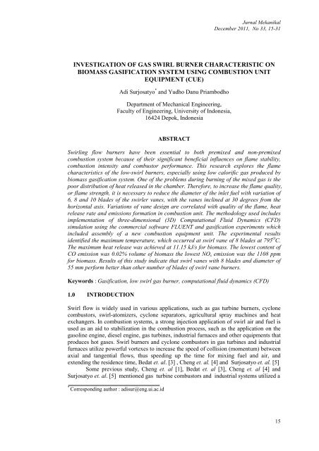
<strong>Jurnal</strong> <strong>Mekanikal</strong>December 2011, No 33, 15-31INVESTIGATION OF GAS SWIRL BURNER CHARACTERISTIC ONBIOMASS GASIFICATION SYSTEM USING COMBUSTION UNITEQUIPMENT (CUE)Adi Surjosatyo * and Yudho Danu PriambodhoDepartment <strong>of</strong> Mechanical Engineering,Faculty <strong>of</strong> Engineering, University <strong>of</strong> Indonesia,16424 Depok, IndonesiaABSTRACT<strong>Swirl</strong>ing flow burners have been essential to both premixed and non-premixedcombustion system because <strong>of</strong> their significant beneficial influences on flame stability,combustion intensity and combustor performance. This research explores the flamecharacteristics <strong>of</strong> the low-swirl burners, especially using low calorific gas produced bybiomass gasification system. One <strong>of</strong> the problems during burning <strong>of</strong> the mixed gas is thepoor distribution <strong>of</strong> heat released in the chamber. Therefore, to increase the flame quality,or flame strength, it is necessary to reduce the diameter <strong>of</strong> the inlet fuel with variation <strong>of</strong>6, 8 and 10 blades <strong>of</strong> the swirler vanes, with the vanes inclined at 30 degrees from thehorizontal axis. Variations <strong>of</strong> vane design are correlated with quality <strong>of</strong> the flame, heatrelease rate and emissions formation in combustion unit. The methodology used includesimplementation <strong>of</strong> three-dimensional (3D) Computational Fluid Dynamics (CFD)simulation using the commercial s<strong>of</strong>tware FLUENT and gasification experiments whichincluded assembly <strong>of</strong> a new combustion equipment unit. The experimental resultsidentified the maximum temperature, which occurred at swirl vane <strong>of</strong> 8 blades at 795 O C.The maximum heat release was achieved at 11.15 kJ/s for biomass. The lowest content <strong>of</strong>CO emission was 0.02% volume <strong>of</strong> biomass the lowest NO x emission was the 1108 ppmfor biomass. Results <strong>of</strong> this study indicate that swirl vanes with 8 blades and diameter <strong>of</strong>55 mm perform better than other number <strong>of</strong> blades <strong>of</strong> swirl vane burners.Keywords : <strong>Gas</strong>ification, low swirl gas burner, computational fluid dynamics (CFD)1.0 INTRODUCTION<strong>Swirl</strong> flow is widely used in various applications, such as gas turbine burners, cyclonecombustors, swirl-atomizers, cyclone separators, agricultural spray machines and heatexchangers. In combustion systems, a strong injection application <strong>of</strong> swirl air and fuel isused as an aid to stabilization in the combustion process, such as the application on thegasoline engine, diesel engine, gas turbines, industrial furnaces and other equipments thatproduces hot gases. <strong>Swirl</strong> burners and cyclone combustors in gas turbines and industrialfurnaces utilize powerful vortexes to increase the speed <strong>of</strong> collision (momentum) betweenaxial and tangential flows, thus speeding up the time for mixing fuel and air, andextending the residence time, Bedat et. al. [3] , Cheng et. al. [4] and Surjosatyo et. al. [5]Some previous study, Cheng et. al [1], Bedat et. al [3], Cheng et. al [4] andSurjosatyo et. al. [5] mentioned gas turbine combustors and industrial systems utilized a*Corresponding author : adisur@eng.ui.ac.id15
<strong>Jurnal</strong> <strong>Mekanikal</strong> December 2011high-swirl type <strong>of</strong> burner in which the swirling motion generated by the injector (orburner) is sufficiently high to produce a fully developed internal recirculation zone at theentrance <strong>of</strong> the combustor. For conventional non-premixed combustion, the role <strong>of</strong> thelarge recirculation zone, also known as the toroidal vortex core, is to promote turbulentmixing <strong>of</strong> fuel and air. In premixed systems, the recirculation zone provides a stable heatsource for continuous ignition <strong>of</strong> the fresh reactants, as refers to the review <strong>of</strong> Syred et.al. [7] for extensive background on the basic processes and practical implementation <strong>of</strong>high-swirl combustors.But according <strong>of</strong> some study <strong>of</strong> Pleasing et. al. [8] and Shepherd [9] low-swirlcombustion is a relatively recent development, is an excellent tool for laboratory researchon flame/turbulent interactions. Its operating principle exploits the “propagating wave”nature <strong>of</strong> premixed flames and is not valid for non-premixed combustion. Premixedflames consume the reactants in the form <strong>of</strong> self-sustained reacting waves that propagateat flame speeds controlled by mixture compositions, thermodynamic conditions, andturbulence intensities. In contrast, non-premixed diffusion flames do not propagate (i.e.,move through the reactants) because burning occurs only at the mixing zones <strong>of</strong> the fueland oxidizer streams. To capture a fast moving turbulent premixed flame as a “standingwave” that remains stationary, low-swirl combustion exploits a fluid mechanicalphenomenon called a divergent flow. As the name implies, divergent flow is anexpanding flow stream. It is formed when the swirl intensities are deliberately low suchthat vortex breakdown, a precursor to the formation <strong>of</strong> flow reversal and recirculation,does not occur. Therefore, the Low <strong>Swirl</strong> Combustion (LSC principle is fundamentallydifferent from the high-swirl concept <strong>of</strong> typical Dry Low NO x (DLN) gas turbines, wherestrong toroidal vortexes are the essential flow elements to maintain and continuouslyreignite the flames. The engineering guideline for the LSB is specified in terms <strong>of</strong> a range<strong>of</strong> swirl number (0.4 < S < 0.55),As part <strong>of</strong> this study, producer gas, a mixture <strong>of</strong> gases from the biomassgasification process that is capable <strong>of</strong> burning fuel and gas, was used. The number <strong>of</strong>elements in producer gas depends on the type <strong>of</strong> biomass and operational conditions. Forexample, CO, H 2 , and CH 4 can be utilized, while N 2 , CO 2 , tar and ash cannot be directlyutilized, Bridgwater [10]. Since quality <strong>of</strong> the gas mixture is unknown at the beginning <strong>of</strong>the gasification process, a tool used to determine the parameters <strong>of</strong> the quality <strong>of</strong> themixing method is Computational Fluid Dynamics (CFD), which provides an analysis <strong>of</strong>the fluid flow in the system using numerical algorithms.The swirl flow effect has usually been used for the combustion and processing <strong>of</strong>materials that are normally considered difficult to burn or process efficiently, such asvegetable refuse, high ash content coals, anthracite, high sulfur oils, and waste gases withlow calorific values. Air and fuel are introduced tangentially at one end and combustiontakes place, primarily near the walls as swirling flow along the chamber towards theexhaust at the other end, Brunner et. al. [11]. A high shear and high property gradientsexist in the high turbulence zone at the interface between the jets <strong>of</strong> fuel and air. And onthe time produces flame combustion with high heat release rates. The main characteristics<strong>of</strong> swirl flow are:• long residence times, which depend upon swirl number and chamber length• a long, thin annular recirculation zone formed internally close to the walls that can beused to enhance flame stabilization• ability to adapt in a two-stage combustor arrangement, with the swirl burner typeflow in the exit being used to provide an afterburning process which ensures completefuel burnout• reduction in combustion chamber size by producing higher rates <strong>of</strong> entrainment <strong>of</strong> theambient fluid and fast mixing near the exit nozzle.16
<strong>Jurnal</strong> <strong>Mekanikal</strong> December 2011The two primary types <strong>of</strong> swirl combustors are the swirl burner and the cyclonecombustion chamber. In the swirl burner, swirling air and c<strong>of</strong>lowing fuel exit into afurnace or the atmosphere, where combustion occurs. In the cyclone burner, air is injectedtangentially into the combustion chamber, where it is mixed with the fuel so thatcombustion occurs. The tangential momentum imparted by the swirling air seems to helpstabilize and enhance mixing in the non-premixed flame. For comparison purposes, thegeometric swirl number, S g , can be used as a non-dimensional measure <strong>of</strong> the angularmomentum added to the flow, Syred et. al. [7]. The swirl number is given by:S =GR G′bangx=R∞∫b0∞∫0ρUWr2 1 2ρ( U − W ) rdr22dr(1)where G ang is the angular momentum in the swirled section and G’ x is the liniearmomentum flux through the unswirled center core and the swirled annulus. This termscan be calculated by integrating the mean axial, U, and the mean swirl, W, velocitycomponents across the burner exit. With the assumption that the distribution <strong>of</strong> the axialflow remains flat, and U and W at the burner exit are kinematically related to the bladeangle as tan α = U/W , the axial flux <strong>of</strong> angular momentum in the annular section is thenwritten as follows:Rb3 32 2⎛ R −( )⎟ ⎞bRcG = 2 ∫ tan = 2 tan ⎜angπρ UaUaα r dr πρUaα(2)⎝ 3R⎠cHere, U a is a mean axial velocity supplied through the swirl annulus. By assuming flataxial velocity distribution, the linear momentum flux from the two regions <strong>of</strong> the burneris then calculated as follows:Gx2 2 2 2 2[ ρU( R − R ) ρUR ]RbRc222πρ Uardr + 2πρUcrdr = πa b c+c cRc0= ∫ ∫(3)where U c is a mean axial velocity through the center core. With Equation (1) as defined,the geometric swirl number for the vane swirl burner is then:S3( 1−R )2tanα2=3= tanα2 U 2 3 1−R1−R + RU2c2a231−R2+ [ m (1/ R22−1)] R2(4)Here, R is the ratio <strong>of</strong> center body to burner radial, R= R c /R b . It is simplified further whenU c /U a is expressed in terms <strong>of</strong> m the mass flux ratio (flow-split) m= m& / m& where massfux through the center body ( m&c) and mass flux through annular body ( m&a). The massflux ratio is the same as the ratio <strong>of</strong> the effective areas <strong>of</strong> the center core and the swirlannulus and can be determined simply by the use <strong>of</strong> standard flow pressure dropprocedure.Earlier swirl combustion studies have typically used very high swirl numbers,generally on the order <strong>of</strong> S g = 1, to ensure the formation <strong>of</strong> a recirculation zone at theca17
<strong>Jurnal</strong> <strong>Mekanikal</strong> December 2011main jet exit, which greatly enhances mixing and causes stabilization <strong>of</strong> the flame. If theeffect <strong>of</strong> this recirculation zone swirl is increased, a jet flame can be reduced in length bya factor <strong>of</strong> five, Chen et. al. [13]. However, another study showed that the reaction aids inthe recirculation vortex formation, since a cold flow test with S g = 1.0 did not show arecirculation vortex, Tangirala et. al. [12]. In another study, some swirl flames with lowenough swirl numbers were associated with lack <strong>of</strong> formation <strong>of</strong> a recirculation vortex.Low swirlconditions apparently have a be study verified that lean flames need to have alower swirl number inorder to be stable, because the swirl velocity can subject thereaction zone to flame strain, which quenches the reaction, Tangirala et. al. [12] and Chenet. al. [13].In conjunction with CFD simulations on the swirl gas burner, a study on thequality <strong>of</strong> the gas mixture in tangential air gasification and a gas swirl burner wasconducted, Agung et. al. [14]. The parameters <strong>of</strong> the measured mixing process were swirlnumber, kinetic turbulent energy, and turbulent intensity. The simulation resultsconcluded that increasing air flow inside the gas burner through tangential flow resultedin a better mixing process. Also, a numerical simulation <strong>of</strong> a turbulent natural gas jetdiffusion flame at a Reynolds (Re) number <strong>of</strong> 9000 in a swirling air stream was reviewed.Results were useful for interpreting the effects <strong>of</strong> swirl inenhancing mixing ratesin the combustion zone and in stabilizing the flame. Theresults showed the generation <strong>of</strong>two recirculating regimes induced by the swirling air stream, Ala [15]. A CFD model wasused to predict the combusting flow field produced by a multi-fuel swirl-stabilizedlaboratory burner with adjustable aerodynamics, which was designed as a scale model <strong>of</strong>an industrial coal burner, Hatziapostolow [16]. Results are reported for two different swirlnumbers and compared to measured velocity and temperature data. The non-premixedcombustion scheme involving the mixture fraction approach was employed and theturbulence-chemistry interaction was accounted for with a Probability Density Functionhaving a β-function shape. For the description <strong>of</strong> turbulence, three turbulence modelswere tested, the standard k-ε model, the RNG k-ε model, and the Realizable k-ε model.Two main problems closely related to the implementation <strong>of</strong> industrial gasburners on ceramic drying, grain and also as a gas potential to partial substitute fuel indiesel engine are:i. Previous testing using the latest gas burner version shows that the quality <strong>of</strong>thegas flame is still low (yellow-red color dominates the gas-flame), as indicatedin Figure 1.Figure 1: <strong>Gas</strong> burner flame with yellow-red color dominationii.Heat release rate <strong>of</strong> the flame, flame performance and measurement <strong>of</strong> productgas flame, such as CO, H 2 , CH 4 , N 2 , CO 2 , are not yet identified.18
<strong>Jurnal</strong> <strong>Mekanikal</strong> December 2011The objective <strong>of</strong> the study is to determine how to improve the performance <strong>of</strong> thecurrent gas burner, including the quality <strong>of</strong> flame, flame temperature, heat transfer rate,efficiency, and reduction <strong>of</strong> CO and NO x emissions.2.0 RESEARCH METHODOLOGYMeasurements and predictions for incorporating the swirl burner with the biomassgasification system were conducted in the current study at the University <strong>of</strong> Indonesia,Department <strong>of</strong> Mechanical Engineering, <strong>Gas</strong>ification Laboratory. Equipment used in thisresearch includes a downdraft gasifier, a cyclone, and a venturi scrubber as gas cleaningequipment, a gas holding tank, a gas burner, and a combustion unit.2.1 Simulation ProcedureThe turbulence model <strong>of</strong> the renormalized group theory (RNG) k-ε consists <strong>of</strong> twoequation models in which the transport equations for two scalar quantities (the turbulentkinetic energy, k and its dissipation rate, ε ) are used to describe the production, diffusionand dissipation <strong>of</strong> turbulence. The RNG k-ε model belongs to the k-εfamily <strong>of</strong> turbulencemodels. Unlike the standard k-ε, the RNG k-ε model was derived using a statisticaltechnique called the Renormalization Group Method model has an additional rate-<strong>of</strong>strainterm in the transport equation ε, to provide a more accurate prediction <strong>of</strong> swirl thanin standard k-ε. When the RNG k-ε model was implemented, the swirl dominated flowoption was used. This option establishes the swirl constant, α o , 0.35.(a)(b)Figure 2 : Model <strong>of</strong> fuel gas burner system (a) and overview <strong>of</strong> swirl burner (b)19
<strong>Jurnal</strong> <strong>Mekanikal</strong> December 2011Dimensions <strong>of</strong> the gas burner system are as follows: fuel inlet with diameter <strong>of</strong> 66mm and length <strong>of</strong> 200 mm; tangential air inlet with diameter <strong>of</strong> 22 mm and length <strong>of</strong> 102mm, and burner with diameter entrance area <strong>of</strong> 96 mm, length <strong>of</strong> 155 mm, and diameterexit area <strong>of</strong> 166 mm. Diameter <strong>of</strong> mixing chamber 102 mm; length is 166 mm.Combustion chamber’s length is 952 mm and diameter is 422 mm. The dimension <strong>of</strong>swirl is 60 mm long, with blades at a tilt angle <strong>of</strong> 30 o , outer dimensions are 60 mm widthand 56 mm diameter. Dimensions <strong>of</strong> cones used 30 mm diameter <strong>of</strong> and 21 mm sidelength. Solid model for the gas burner system is shown in Figure 3.Figure 3 : Solid model gas burner systemTo simplify the simulation, only the swirler burner component <strong>of</strong> the gasifiersystem was used for modeling purposes. A computational mesh pattern <strong>of</strong> this swirlerburner (tetrahybrid mesh), is constructed in Figures 4a and 4b. Note use <strong>of</strong> triangular andquadrilateral mesh. This geometric model makes use <strong>of</strong> the advanced gridding capabilities<strong>of</strong> FLUENT to represent the geometric patterns as closely as possible.(a)(b)Figure 4 : Meshing results with interval size 30 (a); Plane x=0.2 and x=0.5 m (b)The computational model was applied to the current 3-D gas burner system topredict the effect <strong>of</strong> the different swirler values <strong>of</strong> the gas burner to the system’s flowfield. Three variations in swirler value were employed in this investigation (i.e., fixedvane swirlers with 6, 8 and 10 vanes, respectively). These gas burners were parts <strong>of</strong> thebiomass gasifier system. For the current research, simplification <strong>of</strong> the gas burner modelwas required, it was not necessary for the entire biomass gasifier to be simulated.The following equations <strong>of</strong> mass conservation, momentum conservation, energyconservation, RNGturbulence and displacement, the compounds (species transport) areused in the model’s solution :20
<strong>Jurnal</strong> <strong>Mekanikal</strong> December 2011∂ρr+ ∇.( ρυ ) = S m(5)∂t∂ r r r r r( ρ υ)+ ∇.(ρυυ)= −∇p+ ρg+ F(6)∂t∂ r( ρE)+ ∇.(υ(ρE+ p))= −∇.(∑ hjJj) + S∂t∂ ∂ ∂ ∂k( ρ k)+ ( ρkui) = ( αkµ ) + Gk+ Gb− ρ ∈ −YM+ Sk(8)∂t∂x∂x∂xijjj∂r r( ρ Yi) + ∇.(ρυYi) = −∇.Ji+ Ri+ Si(9)∂th(7)where v is velocity vector (m/s), ρ is mass <strong>of</strong> gas type <strong>of</strong> gas (kg/m 3 ), S m is source termdue to the addition to the phase <strong>of</strong> continuous from dispersed phase, P is static pressure(Pa),τ r is stress tensor (Pa) , ρ g r is body gravitational force (N), F r is external body force(N), E is enthalpy (J/kg), h is the enthalpy compound (J/kg), J i is the mass flow ratediffusion compound i (kg/m 2 s 2 ), source term S h is the heat induced reaction, k isturbulence kinetic energy (m 2 /s 2 ), u is velocity (m/s), µ eff is dynamical effectiveviscosity (kg/ms), G k represents generating turbulent kinetic energy due to velocitygradients, G b is turbulent kinetic power due to buoyancy, ε is turbulent dissipation rate(m 2 /s 3 ), Y m represents influence <strong>of</strong> dilatation fluctuations <strong>of</strong> compressible turbulentdissipation rate, S k stands for source terms in the specified user, Y i is mass fraction <strong>of</strong> eachcompound, R i is the net production rate <strong>of</strong> compound i by chemical reaction (kg/m 3 s 2 ),and S i is the source term due to the addition <strong>of</strong> a specific phase i.2.1.1 Finite Rate ReactionThis model was implemented on the burner-nozzle zone because premixing <strong>of</strong> the gasmixture occurred before entering the burner-nozzle. Methane combustion modeling wasnecessary to solve this reaction and was simulated by a two-step chemical mechanism.The methane two-step combustion model consisted <strong>of</strong> the following reactions:CH 4 + 1 ½ O 2 ⇒ CO + 2 H 2 O (10)CO + ½ O 2 ⇒ CO 2 (11)Followed by hydrogen reaction:H 2 + ½ O 2 ⇒ H 2 O (12)Rate expressions for the forward reactions are generalized in Arrhenius form, based onreactant concentrations [R i ] and temperature T:R ef = -ν’ i,k AT n [R a ] a [R b ] b exp{E A /RT} (13)21
<strong>Jurnal</strong> <strong>Mekanikal</strong> December 2011where -ν’ i,k is the molar stoichiometric coefficient for species i in reaction k (positivevalues for reactants, negative values for products), A is pre-exponential factor (consistentunits), T is temperature (˚K), n is temperature exponent (dimensionless), a and b arespecies exponents, and E A is activation energy for the reaction (J/kmol).The influence <strong>of</strong> turbulence time scale k/ε on the reaction rate was taken intoaccount by employing the Magnussen and Hjertager model (1976) [17] :mrR Rk = -4ν k M i ρε⁄kν Mrr(14)R Pk = 2 ν k M i ρε⁄k∑ PmP(15)∑υ MPPPwhere M i is molecular weight <strong>of</strong> species i (kg/kmol), m p is particle mass (kg), m r,P is massfraction <strong>of</strong> a particular reactant R and Product (P), s density (kg/m 3 ). The eddy breakupmodel relates the rate <strong>of</strong> reaction <strong>of</strong> dissipation <strong>of</strong> the Reactant (R) and Product(P),containing eddies, ε /k represents the time scale <strong>of</strong> the turbulent eddies following theeddy breakup model <strong>of</strong> Spalding (1972) [17].The model was applied, without modification, to the combusting. This ensured aconsistent representation <strong>of</strong> the flow and combustion physical processes so that thecomparisons between two cases would be insensitive to the particular turbulence andcombustion models employed. By assuming steady state, the component <strong>of</strong> changeaccording to time (∂/∂t) in the equation above was removed.2.1.2 Boundary ConditionThe boundary condition is as follows:• Composition <strong>of</strong> the gas mass fraction in the producer gas consists <strong>of</strong>: CO (25 %),H 2 (12 %), CH 4 (1.5 %) , and N 2 (51.5 %)• Mean velocity <strong>of</strong> producer gas was 5 m/s for biomass• Tangential air injection velocity was 9.7 m/s for biomass• Producer gas temperature is 200 o C and tangential air temperature was 27 o C.2.2 Experimental Set-UpThe gasification process was conducted on a downdraft gasifier and was equipped with acyclone, wet scrubber, and gas holding as in Figure 5. Air flow rate for the gasificationprocess is 190 lpm and fuel used is biomass (coconut shell), with each analysis shown inTable 1.Table 1: Proximate and ultimate analysis <strong>of</strong> coconut shellsProximate analysis (% weight)Ultimate Analysis (% weight)Moisture5.3 C 47.59Volatile Matter70.7 H 6.0Ash 6.26 O 45.52Fixed CarbonLow Heating Value (kj/kg)17.54 N 0.2222 S 0.0522
<strong>Jurnal</strong> <strong>Mekanikal</strong> December 2011Stabilizer forFlow <strong>Gas</strong>Producer<strong>Gas</strong> <strong>Burner</strong><strong>Gas</strong>ificationreactorParticleCleanerGlass window<strong>Gas</strong> cooler andTar trapFigure 5 : <strong>Gas</strong>ification and gas burner systemA gas swirl burner with a diameter <strong>of</strong> 66 mm was used and three different vanes <strong>of</strong>6, 8 and 10 blades were utilized. The material used for the swirl burners was mild steel.The material could resist temperatures below 1000 K in continuous operation.<strong>Gas</strong> <strong>Burner</strong>TC1 positionTC 2 positionFigure 6 : Combustion equipmentFigure 7 : Schematic <strong>of</strong> the gas burnerIn Figure 6, the gas burner is located inside the combustion unit, which is attachedby two thermocouples placed in a parallel position. For cooling purposes, the outside <strong>of</strong>the combustion unit was blanketed by water jacket, to absorb heat.Table 2 : Operating conditions for turbulent premixed flames<strong>Swirl</strong>-vane bladesFlow Parameter6 8 10Equivalence Ratio, φ 1.25 – 1.84Nominal Heat Release, kW 12.22<strong>Gas</strong> Flow Rate, kg/hr 28.8Flame temperature, o C 750 780 770Temperature at burner exit, o C 490 475 450Range <strong>of</strong> secondary Air Flow Rate, kg/h 936Combustor Pressure, atmAtmospheric pressure<strong>Swirl</strong> Vane Angle30 o23
<strong>Jurnal</strong> <strong>Mekanikal</strong> December 2011Producer gas from the primary chamber was kept constant at 28.8 kg/h. Flow rate<strong>of</strong> secondary air remained constant at 936 kg/h. The operating conditions for the turbulentpremixed flames considered in the present study are summarized in Table 2 above. Thenominal heat release rate is obtained by multiplying the fuel mass flow rate by its nominalheating value <strong>of</strong> 4,482 kJ/m 3 .3.0 RESULTS AND DISCUSSION3.1 <strong>Gas</strong>ification Test and Simulation Before Modification <strong>of</strong> <strong>Swirl</strong> Vane Blades<strong>Gas</strong>ification process was carried out using biomass fuels (coconut shells). <strong>Gas</strong>compostion have taken from gasification process using gas sample bag and be analyzedusing HP 6890 SERIES <strong>Gas</strong> Chromatography (GC) with standard method <strong>of</strong> GPA 2261.<strong>Gas</strong> composition resulting from the gasification process is shown in Table 3.Table 3 : Composition <strong>of</strong> Biomass <strong>Gas</strong>ification <strong>Gas</strong><strong>Gas</strong> CompositionCO 24.7%CH 4 6.7%H 2 15.9%CO 2 11%O 2 1.2%N 2 41%3.1.1 Experimental ResultsFrom the results <strong>of</strong> experiments carried out on the existing gas burner (beforemodification) on a secondary air flow rate with constant gas flow, the most optimalcondition <strong>of</strong> secondary air flow rate was obtained at the flow rate <strong>of</strong> 294 lpm, with theresults for biomass shown in Table 4.Table 4 : Existing gas burner test results at optimum condition (before modification)Thermocouple 1Thermocouple 2Heat ReleaseParameterValue719 0 C657 0 C10.2 kJ/sEfficiency 80.5%CONO X0.05 % Vol1.4 ppm3.1.2 Simulation ResultsSimulations were carried out on existing gas burner using the swirl blades <strong>of</strong> 6 and outerdiameter <strong>of</strong> 66 mm (before modification). Tangential air velocities used were 9.7 m/s,10.7 m/s, and 11.7 m/s, velocity <strong>of</strong> fuel gas from biomass gasification was 5 m/s.24
<strong>Jurnal</strong> <strong>Mekanikal</strong> December 20113.1.2.1 Flame TemperatureThe simulation results identify the temperatures at thermocouple 1 for air velocity <strong>of</strong> 9.7m/s at 1,130 K (857 o C) and at 1,009 K (736 o C) for thermocouple 2, as shown in Figure 8.Contours <strong>of</strong> velocity in a combustion unit distribution are shown in Figure 9. Thesimulation results show about 10% higher values at different flowrates, as compared tothe experiment for biomass fuel.Figure 8 : Thermocouple temperatures distribution on 1 and 2 <strong>of</strong> the simulationFigure 9 : Contour velocity on the air speed tangential 9.7 m/s3.2 Enhancing the Performance <strong>of</strong> the <strong>Gas</strong> <strong>Burner</strong>Results from experimentation on the existing burner gas showed that a maximumtemperature can be produced at around 700 o C. Performance <strong>of</strong> the gas burner should beimproved by reducing the diameter <strong>of</strong> the producer gas path and varying the number <strong>of</strong>blades in the swirl burner. In this study, the diameter was reduced by 10 mm from initialconditions <strong>of</strong> 66 mm to 56 mm. Variations <strong>of</strong> 6, 8 and 10 blades were used.3.2.1 Modeling and Blade Variation <strong>of</strong> the <strong>Swirl</strong> <strong>Burner</strong><strong>Swirl</strong> was used for the optimization process <strong>of</strong> the gas burner in a solid, first drawn andmodeled in 3D as in Figure 10 to simplify the process <strong>of</strong> simulation and manufacturing.25
<strong>Jurnal</strong> <strong>Mekanikal</strong> December 2011Figure 10 Model : <strong>Swirl</strong>er vane blades variation <strong>of</strong> 6, 8 and 10.3.2.2 Simulation and Experiment Results with New <strong>Gas</strong> <strong>Burner</strong>3.2.2.1 Results SimulationFigure 11 shows no significant difference in temperatures indicated by each type <strong>of</strong> swirlpossibly because the plane was only a few centimeters from the cones so that the flamethat formed possessed the same average temperature contours. Maximum temperaturewas approximately 900 o C for thermocouple 1 and 700 o C for thermocouple 2.(a)(b)Figure 11 : Temperature distribution for distance (a) X = 0.2 m (TC1) and (b) X=0.5 m(TC2)Temperature distribution as show in Figure 11 shows a high concentration <strong>of</strong>temperature near the middle area combustion unit, or in the radial direction. The graph onFigure 11a shows TC1 at x = 0.2 m, compared to TC2 at x = 0.5 m, gives highertemperature. Furthermore, TC1 indicates in the center <strong>of</strong> combustion unit, for <strong>Swirl</strong> 8, hasan interesting temperature distribution behavior. It shows that the distribution at thecenter does not reduce immediately, while for swirl vanes 6 and 10 shows the distributionin the center reduce immediately. It is possible, that the momentum <strong>of</strong> mixing process <strong>of</strong>swirl vanes 8 gives high enough kinetic reaction <strong>of</strong> combustion process.Predicted flame distribution shown in Figure 12 indicates that increasing theblade number strengthens the kinetic energy <strong>of</strong> the mixing process. High swirl numberstrengthens the kinetic reaction. But for swirl vane blades 8, the combustion process aftercones produces immediate combustion process, while for swirl vanes 6 and 10, givesdifferent results, namely, a late combustion process. This perhaps, presents a slowlykinetic reaction between gas and air near cones. The strength <strong>of</strong> swirl vanes 8 produces aflame with a high Re number.26
<strong>Jurnal</strong> <strong>Mekanikal</strong> December 2011Figure 12 : Predicted temperature on axial plane:swirls 6, 8 and 103.2.2.2 Manufacturing <strong>Swirl</strong> <strong>Gas</strong> <strong>Burner</strong>After using simulation to predict the temperatures and composition <strong>of</strong> the CO gas, thefabrication <strong>of</strong> the hub, cones and the swirl blades <strong>of</strong> the gas burner were done as shown inFigure 13 and Figure 14. This followed by a serial <strong>of</strong> laboratory tests and compared withthe simulation results.HubconesFigure 13 : Hub and cones gas burner27
<strong>Jurnal</strong> <strong>Mekanikal</strong> December 2011Figure 14 : <strong>Swirl</strong>ers with 6, 8 and 10 vane blades3.2.3 Experiment using Biomass FuelResults <strong>of</strong> the experiment was performed using an air flow rate in a gas burner <strong>of</strong> 294lpm, and a gas flow rate <strong>of</strong> 120 lpm for each swirl and are summarized below.3.2.3.1 Flame TemperatureTemperature range in thermocouple 1 (TC1) was 765 - 795°C, while the range forthermocouple 2 (TC2) was 624 - 694°C, as shown in Figure 15. The maximumtemperature occurred in the swirler <strong>of</strong> 8 vane blades, where there was a mixing <strong>of</strong> air andfuel in the gas burner and a favorable internal recirculation zone. The residence time <strong>of</strong> agas burner with 8 blades is longer due to a good internal recirculation zone that makes thefuel came out through the burner gas channel and burned completely before leaving thecombustion chamber. Thus, along with the complete combustion <strong>of</strong> the gaseous fuel, ahigher flame temperature was obtained.1000Temperature ( 0 C)8006004002000TC1TC24 6 8 10 12Number <strong>of</strong> <strong>Swirl</strong> BladeFigure 15 : Comparison between different number <strong>of</strong> swirler vane blades3.2.3.2 Heat ReleaseExperimental results Figure 16 show that the heat release produced was 10.3 kJ/s – 11.15kJ/s. Maximum heat release rate occurred in swirl with 8 blades. Heat release rate isobtained from the transfer <strong>of</strong> heat produced during burning to the water surrounding thecombustion chamber.28
<strong>Jurnal</strong> <strong>Mekanikal</strong> December 2011Heat Release Rate (kJ/s)11.51110.5109.54 6 8 10 12Number <strong>of</strong> <strong>Swirl</strong> BladeFigure 16 : Heat release at different number <strong>of</strong> swirler vane blades3.2.2.3 Combustion EfficiencyCombustion efficiency is the result <strong>of</strong> color content in producer gas is shared with heatrelease from the combustion process. Experimental results show improved efficiencyfrom 83.1% to 85.5% for the producer gas as shown in Figure 17. Maximum combustionefficiency occurred for the swirler with 8 blades. Oxygen levels in the flue gas affect theefficiency; less oxygen in exhaust gas promotes greater combustion efficiency.86Combustion Efficiency(%)85848382814 6 8 10 12Number <strong>of</strong> <strong>Swirl</strong> BladeFigure 17 : Combustion efficiency at different number <strong>of</strong> swirler vane blades3.2.2.4 Composition COCO content in flue gas was between 0.02 - 0.03 % as shown in Figure 18. The content <strong>of</strong>CO generated is still below the 4.5 % volume emission standards for motor vehicleexhaust emission levels <strong>of</strong> CO gas. <strong>Swirl</strong> vanes with 8 blades appear to reduce volumecontent levels <strong>of</strong> CO emissions by at least 0.02 % by producing turbulence leading tomore complete combustion.29
<strong>Jurnal</strong> <strong>Mekanikal</strong> December 2011CO (% Volume)0.0350.030.0250.020.0150.010.00504 6 8 10 12Number <strong>of</strong> <strong>Swirl</strong> BladeFigure 18 : Content <strong>of</strong> CO at different number <strong>of</strong> swirler vane blades4.0 CONCLUSIONSi. Initial test gas burner (before modification) with swirler vanes <strong>of</strong> 6 blades anddiameter <strong>of</strong> 66 mm, produces a maximum flame temperature <strong>of</strong> ± 700 o C. Heatreleased by the combustion unit equipment <strong>of</strong> 9.2 kJ/s - 10 kJ/s, efficiency <strong>of</strong> 78% to 80 % and CO concentration about 0.05 %ii. Simulation using swirlers (after modification) with diameter <strong>of</strong> 56 mm and 6, 8and 10 vane blades show maximum temperatures approximately <strong>of</strong> 795 o C, thelowest CO emmision occurred at 8 swirler vane blades with a composition rangebetween 0.13% to 0.14% volume.iii. Experiments were conducted with a diameter <strong>of</strong> 56 mm and the number <strong>of</strong> swirlblades <strong>of</strong> 6, 8 and 10. The swirl vanes blade <strong>of</strong> 8 reached maximum flametemperature <strong>of</strong> 795 O C, the maximum heat release <strong>of</strong> 11.15 kJ/s, 85.5 % <strong>of</strong>combustion efficiency and produces a minimum content <strong>of</strong> 0.02 % vol CO.iv. <strong>Swirl</strong> burner with number <strong>of</strong> vane blades <strong>of</strong> 8 could improve the gas burnerperformance from existing gas burner. Increasing <strong>of</strong> flame temperature, heatrelease rate, combustion efficiency and decreasing <strong>of</strong> CO concentration.ACKNOWLEDGMENTSThe authors would like to address acknowledgment to Fajri Vidian, Yudo DanuPriambodo, Raka, Raja and Anggariawan for their assistant and supporting duringreporting and conducting <strong>of</strong> the research work. Also the acknowledgment goes to DRPMUI (Research Development and Management Center, University <strong>of</strong> Indonesia) throughRUUI (Research Excellence University <strong>of</strong> Indonesia) program year 2010.REFERENCES1. Cheng, R.K., D. Littlejohn, P. Strakey, and T. Sidwell, 2009. Laboratory<strong>Investigation</strong>s <strong>of</strong> Low-<strong>Swirl</strong> Injectors with H 2 and CH 4 at <strong>Gas</strong> Turbine Conditions.Proc. Comb. Inst., p.32.2. Chan, C.K. et al., 1992 “Freely Propagating Open Premixed Turbulent FlamesStabilized by <strong>Swirl</strong>,”Proc. Comb. Inst., 24 p 511-518;30
<strong>Jurnal</strong> <strong>Mekanikal</strong> December 20113. Bedat, B. and Cheng, R.K., 1995.“Experimental Study <strong>of</strong> Premixed Flames inIntense Isotropic Turbulence,” Combustion and Flame 100, no. 3 p 485-494;4. Cheng, R.K., 1995, “Velocity and Scalar <strong>Characteristic</strong>s <strong>of</strong> Premixed TurbulentFlames Stabilized By Weak <strong>Swirl</strong>,” Combustion and Flame 101, no.1-2 p.1-14.5. Surjosatyo, A. and Ani, F.N., 2005. Experimental and Prediction <strong>of</strong> theDevelopment <strong>of</strong> Low-Calorific <strong>Swirl</strong> <strong>Burner</strong>, Reric International Energy Journal,Asian Institute Technology (AIT), Bangkok,Vol 6.No 2.6. Surjosatyo, A. and Ani, F.N., 2002. “Development <strong>of</strong> <strong>Swirl</strong> <strong>Burner</strong> Incorporatedwith a Biomass Combustion System”. 6 th Asia-Pacific International Symposiumon Combustion and Energy Utilization, Kuala Lumpur, Malaysia.7. Syred. N. and J.M. Beer, 1974. “Combustion in <strong>Swirl</strong>ing Flow: A Review,”Combustion and Flame 23 p. 143-201.8. Plessing. T. et al., 2000. “Measurement <strong>of</strong> the Turbulent Burning Velocity andthe Structure <strong>of</strong> Premixed Flames on a Low <strong>Swirl</strong> <strong>Burner</strong>,” Proc. Comb. Inst. 28p 359-366.9. Shepherd. I. G. et al., 2002 “Premixed Flame Front Structure in IntenseTurbulence,”Proc. Comb. Inst. 29 p.1833-1840.10. Bridgwater, A.V. 1995. The technical and economic feasibility <strong>of</strong> biomassgasification for power generation. Fuel. Vol 74 No.5, pp. 631-653.11. Brunner, C.R. 1985. Hazardous Air Emission form Incinerator, Chapman & Hall.12. Tangirala, V., Chen, R. H., and Driscoll, J. F., 1987, ”Effect <strong>of</strong> Heat Release and<strong>Swirl</strong> on the Recirculation within <strong>Swirl</strong>-Stabilization Flames,” CombustionScience and Technology, Vol. 51, pp. 75-95.13. Chen, R. H., and Driscoll, J. F., 1988, “The Rule <strong>of</strong> the Recirculation Vortex inImproving Fuel-Air Mixing within <strong>Swirl</strong>ing Flames,” Twenty-Second Symposium(International) on Combustion, Combustion Institute, Pittsburgh, pp. 531-440.14. Agung Hidayat and A. Surjosatyo, 2008. Cold flow simulation on a Biomass<strong>Gas</strong>ification. Final Year Project, Departemen Teknik Mesin, FT, UI, Indonesia.15. Ala Qubbaj, 2005. Numerical Simulation <strong>of</strong> Natural <strong>Gas</strong>-<strong>Swirl</strong> <strong>Burner</strong>. FinalTechnical Report, University <strong>of</strong> Texas Pan American.16. Hatziapostolou, A., et. al., 2006. CFD modeling <strong>of</strong> the swirl-stabilised flameproduced by a laboratory-scale combustor: selection <strong>of</strong> the turbulence model.Proceedings <strong>of</strong> the 4th WSEAS Int. Conf. on Heat Transfer, Thermal Engineeringand Environment, Elounda, Greece, pp 83-88.17. Fluent Inc, 6.3. , “User Guide”, Fluent Incorporated, Lebanon31