FLOW BEHAVIOUR AROUND WINGLETS - Jurnal Mekanikal
FLOW BEHAVIOUR AROUND WINGLETS - Jurnal Mekanikal
FLOW BEHAVIOUR AROUND WINGLETS - Jurnal Mekanikal

Create successful ePaper yourself
Turn your PDF publications into a flip-book with our unique Google optimized e-Paper software.
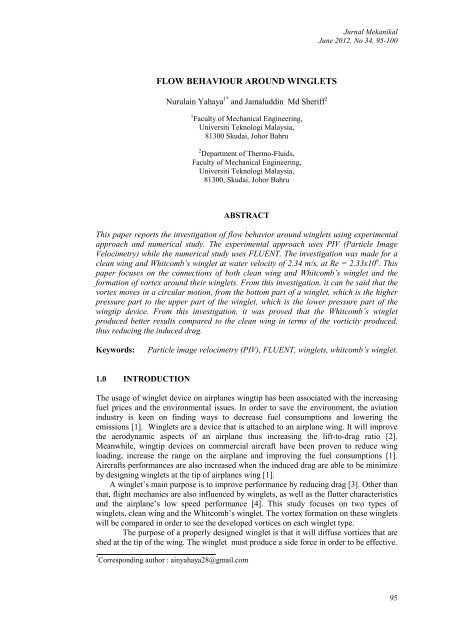
<strong>Jurnal</strong> <strong>Mekanikal</strong>June 2012, No 34, 95-100<strong>FLOW</strong> <strong>BEHAVIOUR</strong> <strong>AROUND</strong> <strong>WINGLETS</strong>Nurulain Yahaya 1* and Jamaluddin Md Sheriff 21 Faculty of Mechanical Engineering,Universiti Teknologi Malaysia,81300 Skudai, Johor Bahru2 Department of Thermo-Fluids,Faculty of Mechanical Engineering,Universiti Teknologi Malaysia,81300, Skudai, Johor BahruABSTRACTThis paper reports the investigation of flow behavior around winglets using experimentalapproach and numerical study. The experimental approach uses PIV (Particle ImageVelocimetry) while the numerical study uses FLUENT. The investigation was made for aclean wing and Whitcomb’s winglet at water velocity of 2.34 m/s, at Re = 2.33x10 6 . Thispaper focuses on the connections of both clean wing and Whitcomb’s winglet and theformation of vortex around their winglets. From this investigation, it can be said that thevortex moves in a circular motion, from the bottom part of a winglet, which is the higherpressure part to the upper part of the winglet, which is the lower pressure part of thewingtip device. From this investigation, it was proved that the Whitcomb’s wingletproduced better results compared to the clean wing in terms of the vorticity produced,thus reducing the induced drag.Keywords:Particle image velocimetry (PIV), FLUENT, winglets, whitcomb’s winglet.1.0 INTRODUCTIONThe usage of winglet device on airplanes wingtip has been associated with the increasingfuel prices and the environmental issues. In order to save the environment, the aviationindustry is keen on finding ways to decrease fuel consumptions and lowering theemissions [1]. Winglets are a device that is attached to an airplane wing. It will improvethe aerodynamic aspects of an airplane thus increasing the lift-to-drag ratio [2].Meanwhile, wingtip devices on commercial aircraft have been proven to reduce wingloading, increase the range on the airplane and improving the fuel consumptions [1].Aircrafts performances are also increased when the induced drag are able to be minimizeby designing winglets at the tip of airplanes wing [1].A winglet’s main purpose is to improve performance by reducing drag [3]. Other thanthat, flight mechanics are also influenced by winglets, as well as the flutter characteristicsand the airplane’s low speed performance [4]. This study focuses on two types ofwinglets, clean wing and the Whitcomb’s winglet. The vortex formation on these wingletswill be compared in order to see the developed vortices on each winglet type.The purpose of a properly designed winglet is that it will diffuse vortices that areshed at the tip of the wing. The winglet must produce a side force in order to be effective.* Corresponding author : ainyahaya28@gmail.com95
<strong>Jurnal</strong> <strong>Mekanikal</strong>, June 2012The side forces reduce the inflow above the wing at the tip, and the outflow below thewing at the tip. The reduction in the inflow and outflow help to normalize the liftdistribution along the entire span of the wing, just as a wing with a higher aspect ratio willhave a more even lift distribution [5]. This study was conducted using two methods, theexperimental method, using PIV and the numerical analysis using FLUENT.2.0 LITERATURE STUDYWinglets belong to the class of wingtip devices aimed to reduce induced drag. Selectionof the wingtip device depends on the specific situation and the airplane model. In the caseof winglets, the reduction of the induced drag is accomplished by acting like a small sailwhose lift component generates a traction force, draining energy from the tip vortices [6].Studies concerning the efforts to decrease the fuel consumptions and loweremissions are the interest of the aviation industry, especially in the era of rising fuelprices and environmental issues. These researches are into a device that will providelonger range and more resourceful fuel consumption rates especially to commercialaircraft. It was found that there are two wingtip devices that will provide better fuelconsumption rates and could provide longer range, which are the winglets and the rakedwingtips [1].There is seven percent increase of the aircraft’s range at cruise conditions (fullspeed conditions) for aircrafts with wings designed with winglet compared to wingwithout winglets. Other than that, wing with winglets or wingtip devices on commercialaircraft are found to have lower wing loading and better fuel consumption rates. All theadvantages of the winglets and raked wingtip performances are due to its ability to reducethe induced drag, or the drag generated during take-off by a 3-dimensional finite wing [1].The induced drag, or the drag generated during take-off is due to the difference inpressure of the upper and lower surfaces of an aircraft wings. The high pressure part is onthe lower surface of the wing while the lower pressure part is located on the upper surfaceof the wing. The difference in pressure on the wing will form a net lifting force that isnormal to the free stream airflow [1]. The difference of pressure on a clean wing, (a wingwith no wingtip devices), will cause air to flow from the lower surface to the uppersurface of the wing at the wingtips. The flow of air from the lower surface of the wing tothe upper surface of the wing at the wingtips produces a downwash onto the top of thewing, as illustrated in Figure 1:Figure 1: Pressure distribution on a wingDrag is caused by the induced drag that is created by the downwash of airflowonto the upper surface of the wing at the wingtips thus producing vortices that trail in theaircraft’s wake. The most important wingtip devise’s functions is reduce the induced dragand consequently, the trailing vortex strength. By minimizing the induced drag, and thusthe wingtip vortices produced by an aircraft’s wing, the energy required to create the tipvortices can be conserved and the total drag on the wing reduced. The coefficient for theinduced drag over a 3-D wing (C Di ) is given by:96
<strong>Jurnal</strong> <strong>Mekanikal</strong>, June 2012C Di =2C Lπ e AR(1)where:CL = lift coefficient,e = Oswald efficiency factorAR = aspect ratio3.0 EXPERIMENTAL RIG APPARATUSExperiments were conducted by submerging the winglet devices in a water tunnel. Thetunnel was filled with water flowing at constant velocity of 2.34 m/s, with inlet and outletvalves to control its velocity. Laser was focused on the winglet devices while the cameracaptured the vortex formation along the winglet at certain speed. The experimental setupis illustrated as Figure 2.Figure 2: Experimental setup for PIV3.1 Experimental (PIV) TechniquesThe experimental images were recorded after the velocity in the water tunnel stabilized(around 5 minutes). The winglet used was made of acrylic (Perspex), with 3mm thicknessand 7 cm length. Meanwhile, the water tunnel was made from acrylic, with 10mm height,10mm width and 90cm length.The flow is laminar if Re < 2300, in transition mode if 2300< Re 4000. To construct the water tunnel, the entrance length requiredfor the velocity and the dimensions of the water tunnel has been taken into consideration.The Re used in this experiment was 2.33x10 6 .3.2 Numerical Analysis (FLUENT) TechniquesThe numerical analysis was performed using two types of software: the two-dimensionalmodelling using GAMBIT software and a solver using FLUENT 6.3. To analyze thewinglet devices problem, the iteration process was used to obtain converged solution.The time-step chosen for this problem was 0.05 seconds, with a convergencefactor of 0.01. The solver used for this problem was Spalart-Allmaras because of itssuitability to process flow in a closed area with one cross section.97
<strong>Jurnal</strong> <strong>Mekanikal</strong>, June 20124.0 RESULTSFigure 3(a) : Streamline of a clean wing configuration using PIV at 2.34 m/sFigure 3(b) : Streamline of a clean wing configuration using FLUENT at 2.34 m/sFigure 3(c): Streamline of a Whitcomb winglet configuration using PIV at 2.34 m/s98
<strong>Jurnal</strong> <strong>Mekanikal</strong>, June 2012Figure 3(d): Streamline of a Whitcomb winglet configuration using FLUENT at 2.34 m/sBased on images obtained using PIV and FLUENT on a clean wing, as illustratedin Figure 3(a) and Figure 3(b), it can be seen that the vortex developed are moving in acircular motion, with the vortex moving from the bottom part of the clean wing to theupper part of the wing. It can be seen that the vortex formation is fully developed at thetip of the wing, thus creating more drag on the wing. When the drag is higher, it creates amore drag to lift ratio and becomes harder for the air plane with this configuration to takeoff and land.Meanwhile, based on the images obtained using PIV and FLUENT on aWhitcomb winglet, as illustrated in Figure 3(c) and Figure 3(d), it can also be seen thatthe vortex developed is moving in a circular motion, with the vortex moving from thebottom part of the clean wing to the upper part of the wing. There are some differences inthese images compared to images from Figure 3(a) and 3(b). The vortex developedaround the Whitcomb winglet has weaker vortices. The circular streamlines are not fullydeveloped indicating that this type of winglet is successful in decreasing the drag profile.When the streamline is weaker, the drag is lower thus increasing the performance of theairplane.5.0 CONCLUSIONBased on the investigation of the flow behavior around winglets, it can be said that theflow behavior of the wingtip devices can be successfully studied using PIV and FLUENT.It was also found that the streamlines moves from the down side of the tip which is thehigh pressure side, towards the upper side of the tip, which is the lower pressure side. Itcan be seen that the vorticity magnitude at the tip of Whitcomb’s winglet is the lowest,thus reducing the induced drag.REFERENCES1. Babigian R. Hayashibara S. 2009. Computational Study of the Vortex WakeGenerated by a Three-Dimensiona l Wing with Dihedral, Taper, and Sweep.27th AIAA Applied Aerodynamics Conference. AAIA Paper 2004-4107-148.2. Myong H.W. Jo W.C.2011. Visualization and PIV study of wing-tip vortices forthree different tip configurations. Aerospace Science and Technology.Doi:10:101699
<strong>Jurnal</strong> <strong>Mekanikal</strong>, June 20123. Maughmer M.2003. Design of Winglets for High Performance Sailplanes.Journal of Aircraft, Vol 40, No 6, 1099-1106.4. Hantrais-Gervois J. Rapin M. 2006. Aerodynamic and Structural Behaviour of aWing Equipped with a Winglet at Cruise. 44 th AAIA Aerospace Sciences Meetingand Exhibit, AAIA Paper 2002-1489.5. Weierman J and Jacob J.D.2010. Winglet Design and Optimization for UAVs.28th AIAA Applied Aerodynamics Conference. AAIA Paper 2010-4224-778.6. Mattos B.S. Macedo A.P. da Silva Filho D.H.2003. Considerations about WingletDesign. 21st Applied Aerodynamics Conference. AAIA Paper 2003-3502.100