View - Jurnal Mekanikal - UTM
View - Jurnal Mekanikal - UTM
View - Jurnal Mekanikal - UTM

Create successful ePaper yourself
Turn your PDF publications into a flip-book with our unique Google optimized e-Paper software.
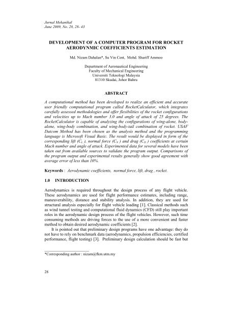
<strong>Jurnal</strong> <strong>Mekanikal</strong>, June 2009For the case at higher angle-of-attack that the effects of the shed vortices aresomewhat more involved [4]. For high-aspect-ratio, unswept subsonicconfigurations, the flow remains attached over the lifting panels up to angles ofattack approaching the stall. Therefore, rockets with such configurations tend tohave a larger value of linear lift, and as a result, stall occurs quicker as a function ofangle of attack. For swept and low-aspect-ratio configurations, the trailing vorticesare shed at progressively more inboard stations as the angle of attack is increased.The effect appears in the downwash field and hence in the lift generated by the aftpanel. The nonlinear cross-flow contribution to body lift is also sizable at higherangles. This cross-flow lift is caused by a pair of body vortices that can alsostrongly affect the lift contributions from the panels.2.2 Drag Coefficient, C DDrag is the most difficult aerodynamic force to predict. There are severalcomponents that have a combined effect on the total drag; they are skin frictiondrag, wave drag, and base drag. These components are affected by factors includingconfiguration geometry, Mach number, Reynolds number, angle of attack and bodyroughness [7]. The total drag is defined as the sum of zero-lift drag and induceddrag [8].Total Drag = Zero-lift Drag + Induced Drag (1)Drag break down method is used in analyzing the drag of an aircraft, bybraking down the drag of an aircraft into those caused by its components. Therefore,the total vehicle drag at angle-of-attack given by the USAF Datcom can be slightlymodified to suit the rocket with cruciform tail.Total Drag = wing-body zero-lift drag + wing-body induced drag2.3 Wing Maximum Lift,+ vertical tail zero-lift drag + horizontal-tail zero-lift drag+ horizontal-tail induced drag (2)CL maxAt subsonic speeds, Shrenk’s Method has been used in the program to estimate thewing maximum lift. The approximated spanwise location where the stall will firstoccur can be calculated for an untwisted tapered wing byηstall= 1− λ(3)where λ is the wing taper ratio [4].At supersonic speeds the lift is limited by the wing geometric considerationsrather than by flow separation [4]. The semi empirical method presented in theDatcom has been used in the program to estimate the wing maximum lift atsupersonic speeds.30
<strong>Jurnal</strong> <strong>Mekanikal</strong>, June 2009Figure 1: Basic Structure of RocketCalculator.31
<strong>Jurnal</strong> <strong>Mekanikal</strong>, June 20093.0 SOFTWARE METHODOLOGY AND IMPLEMENTATIONMicrosoft Visual Basic .NET (VB.NET) has been chosen to develop theRocketCalculator because it is easy-to-learn and user-friendly. Visual Basic .NETis the next generation of Visual Basic, but it has also a significant departure fromprevious generations [9]. Despite all appearances Visual Basic is really very easy touse, since the complexity of the language is hidden in tools provided to developersby Microsoft [10]. All the rapid application development (RAD) tools thatdevelopers have come to expect from Microsoft are found in Visual Basic .NET,including drag-and-drop design and code behind forms. In addition, new featuressuch as automatic control resizing eliminate the need for complex resize code. Newcontrols such as the in-place menu editor deliver visual authoring of menus directlywithin the Windows Forms Designer. Flow Chart in Figure 1 shows the basicstructure of the RocketCalculator.3.1 Welcome ScreenThe first screen when the program is loaded is the welcome screen. This can beshown in Figure 2. The screen serves as the ‘cover’ of the program. It gives thegeneral information on where the program is developed, who have credits on it andwhat the program is.<strong>View</strong>LimitationsCalculationExitProgram32
<strong>Jurnal</strong> <strong>Mekanikal</strong>, June 2009Figure 2 : Welcome Screen3.2 Calculator ScreenThe calculator screen is the most important part of this program. Figure 3 shows theinterface of the calculator screen. It serves as the input data collector. It is designedas simple as possible to be user friendly. A reference figure is given fordimensioning guidance. Only dimensions in length are needed to be keyed in fordimensioning input, while other data such as leading-edge angle, taper ratio andaspect ratio will be generated automatically. A ‘Reset’ button is placed besides the‘Calculate’ button. It is useful if the user wishes to erase the entire data keyed inpreviously.Figure 3: The interface of the calculator screen3.3 Result ScreenResult screen will pop up if the ‘Calculate’ button of the calculator screen is clicked.It presents the results data in both the graphical and table form. Example of results33
<strong>Jurnal</strong> <strong>Mekanikal</strong>, June 2009screen is illustrated in Figure 4 that shows the graph of normal-force and dragcoefficients versus angle of attack for body alone configuration at Mach Number 2.Figure 4: Result screen3.4 Rocket data ScreenRocket data screen will be shown when the ‘view’ menu of the result screen inselected. This screen (Figure 5) contains all the geometric information of the rocketmodel used in the program calculation. This is particularly useful for user to keeprecord and or to verify the geometrics of the rocket designed.Some other additional functions are contained in the program such as ‘Print’and ‘Save’ function. These two functions only occur in the result screen and rocketdata screen.34
<strong>Jurnal</strong> <strong>Mekanikal</strong>, June 2009Figure 5: Rocket data screen.3.5 Software LimitationsThe followings are the limitations of the program developed:i. Operational speeds, M ≤ 3. 0b'ii. The ratio of the wing span to tail span must be less than or equal to 1.5, ≤ 1. 5b"diii. The ratio of the body diameter to wing span is less than 0.8, ≤ 0. 8b35
<strong>Jurnal</strong> <strong>Mekanikal</strong>, June 2009angle 30° measured in a plane perpendicular to the edges. For wing with supersonicleading-edge shock detached condition analysis is made at Mach number 1.6. Forwing with supersonic leading-edge shock attached condition, analysis is made atMach number 2.86. For wing with subsonic leading edge condition, analysis ismade at Mach number 2.0. Comparisons of the program output and experimentalresults by [11] generally show good agreement, and the results are shown in Figures6 to 8.Table 2: Wing model for supersonic with subsonic leading-edge conditionSpan, bRoot Chord,Tip Chord, ctcr_15.24 cm30.48 cm0.00 cmMean Chord, c20.32 cmTaper Ratio, λ 0Leading Edge Angle, Λ 75.96 degLEMaximum thickness, ⎛ t ⎞⎜ ⎟⎝ c ⎠max6.25 %cPosition of the maximum thickness from LE 11.6627 %c1.41.2Normal Force Coefficient, CN and Drag Coefficient, CD10.80.60.4CN ExperimentCN ProgramCD ExperimentCD Program0.200 5 10 15 20 25 30Angle of attack, α, degFigure 6: Comparison of problem output with previously published data forsupersonic leading-edge shock detached condition at Mach number 1.637
<strong>Jurnal</strong> <strong>Mekanikal</strong>, June 20090.8Norm al Force Coefficient, CN and Drag Coefficient, CD0.70.60.50.40.30.20.1CN ExperimentCN ProgramCD ExperimentCD Program00 5 10 15 20 25 30Angle of attack, α, degFigure 7 : Comparison of program output with previously published data forsupersonic leading-edge shock attached condition at Mach number 2.86.10.90.8Normal Force Coefficient, CN0.70.60.50.40.3CN ExperimentCN Program0.20.100 5 10 15 20 25 30 35Angle of attack, α, degFigure 8 : Comparison of program output with previously published data forsupersonic wing with subsonic leading-edge at Mach number 2.038
<strong>Jurnal</strong> <strong>Mekanikal</strong>, June 20094.2 Body-Alone ConfigurationIn figures 9 and 10 the results of the program RocketCalculator are compared withexperimental data by [12] and [13] for body-alone configurations with bodyfineness ratio 10 and nose fineness ratio 2.5. The analysis is made at Marchnumbers (M) 0.6 and 2.0 respectively. Comparisons of the program output andexperimental results generally illustrate a good agreement within the range of ±10%error.Normal Force Coefficient, CN32.521.510.50Body-Alone L/D = 10, Ln/D = 2.5M = 0.60 5 10 15 20 25 30CN ProgramCN ExperimentFigure 9 : Comparison of program output with experiment for body-aloneat M = 0.6Normal Force Coefficient, CN6543210Body-Alone L/D = 10, Ln/D = 2.5M = 2.00 5 10 15 20 25 30CN ProgramCN ExperimentFigure 10: Comparison of program output with experiment for body-aloneat M = 2.039
<strong>Jurnal</strong> <strong>Mekanikal</strong>, June 20094.3 Wing-Body ConfigurationThe configurations of wing-body combination of rocket model for this comparisonare taken from an undergraduate thesis of Universiti Teknologi Malaysia (<strong>UTM</strong>)[14]. The orthographic drawing of the rocket model is shown in Figure 11 and thespecification and configuration detail are given in Table 3.Figure 11 : Rocket Model ConfigurationTable 3 : Specification and Configuration of Rocket ModelGENERAL DESCRIPTIONRocket Model<strong>UTM</strong>-X1Overall Length, L1050 mmDiameter, D70 mmNose TypeConicalNose Length, l N198.49 mmAfterbody Length, l A718.51 mmL/D Ratio 15Weight without warhead68.67 N (7 kg)WarheadWDU-500X/B GPFLaunchersLAU-5005MotorsC17 (RLU-5004/B) Rocket MotorRange3.6 KmWING CONFIGURATIONWing PlatformsClipped Tip DeltaWing Cross Section ShapeModified Double-WedgeWing Span, b190 mmWing Area 16800 mm 2Wing Aspect Ratio, AR 1.1828Root Chord, C r98 mmTip Chord, C t42 mmWing Thickness, t2 mmWing Taper Ratio, λ 0.4286Wing Leading Edge Sweptback Angle, Λ LE 43.03 o40
<strong>Jurnal</strong> <strong>Mekanikal</strong>, June 2009Boattail TypeBoattail Length, l bBase Diameter, D bBoattail Angle, βBOATTAIL CONFIGURATIONConical35 mm63.88 mm5 oThe rocket model was tested in wind tunnel in the Aeronautical Laboratory,Faculty of Mechanical Engineering, (<strong>UTM</strong>). The wind tunnel tests were undertakenin the 2.0m (width) x 1.5m (height) x 5.8m (length) test section and the averageturbulence intensity at the centre of the working section is 0.04%. The maximumMach number is 0.235, which corresponds to a velocity of 80 m/s (280 km/h).Figure 12 shows the comparison between the data of wind tunnel testing andprogram RocketCalculator. The data were taken at a velocity of 70 m/s for angle ofattack up to 25 degree. The model was tested at extremely low velocities due to thelimitation of wind tunnel availability. Nevertheless, the graph of lift coefficientversus angle of attack show that the agreement between the predicted data byprogram output and experimental data is quit satisfactory which is reliable withaverage error of less than 10%.1.61.4Lift Coefficient,CL1.210.80.60.40.200 5 10 15 20 25 30Angle of Attack, α, degCL ProgramCL ExperimentFigure 12 : Comparison results between program and experiment for wing-bodycombination at velocity 70 m/s4.4 Maximum LiftAn investigation of the maximum lift of wings at supersonic speeds was carried outby [15]. Two tested results for 3 different wings were taken from their report forvalidation purpose. For wings at supersonic speeds, the maximum lift is determinedby those geometric parameters that influence the wing lift-curve slope, i.e., aspectratio, sweep, taper ratio, and Mach number. The comparison is shown in Table 4.41
<strong>Jurnal</strong> <strong>Mekanikal</strong>, June 2009Comparison of the experimental data and program output shows that the maximumlift falls within the ± 8% error range.Table 4 : Comparisons of experimented maximum lift and program output forwings at supersonic speedsMachResultTriangular,Triangular,Rectangular,1.55 2.32Experiment Program % error Experiment Program % error1.03 1.1212 8.1341 1.00 1.0004 0.041.10 1.1274 2.4304 1.05 1.0031 -4.67551.15 1.1395 -0.9215 -- -- --5.0 CONCLUSIONA user friendly computer program named RocketCalculator has been developed byusing the technology of Visual Basic.Net. USAF Datcom Method has been themain reference to develop the program’s algorithm. The software developedenables users to estimate the linear and nonlinear aerodynamic coefficients of wingalone,body-alone, wing-body and wing-body-tail combinations at speeds belowMach number 3.0 and angle of attack up to 25 degree.For normal-force, lift, drag, and maximum lift coefficients and itscorresponding angles of attack, the comparisons of the program outputs withexperimental data indicate the errors within ± 10%. Generally, aerodynamiccoefficients of rockets estimated by RocketCalulator are in good agreement withexperimental results, and adequately provide data for preliminary design purposes.However, more additional data for validation purposes would be desirable.REFERENCES1. Frank G. Moore 2000, Approximate Methods for Weapon Aerodynamics,American Institute of Aeronautics and Astronautics, Inc., Danvers,Massachusetts.2. Chia-Wei Hsu 1995, The Use of Datcom Method and Wind Tunnel Testing forSpoonbill Unmanned Aerial Vehicle Aerodynamic Analysis. Master Thesis.National Cheng Kung University, Taiwan.3. Filippone A. 2008, Comprehensive Analysis of Transport Aircraft FlightPerformance. Progress in Aerospace Sciences, Volume 44, Issue 3, Pages 192-236.42
<strong>Jurnal</strong> <strong>Mekanikal</strong>, June 20094. Hoak D.E. and Finck R.D 1978,USAF Stability and Control Datcom. GlobalDocuments.5. Williams J.E, Vukelich S.P. 1979, The USAF stability and control digitalDatcom, vol. i. Technical Report AFFDL TR-79-3032. McDonnell- Douglas.6. Marie-Louise Roy and Steven M. Sliwa 1983, A Computer Program forObtaining Airplane Configuration Plots from Digital Datcom Input Data,NASA TM 84639, NASA Langley Research Center.7. Thomas J. Sooy and Rebecca Z.Schmidt 2004, Aerodynamic Predictions,Comparisons, and Validation using Missile Datcom (97) and Aeroprediction 98(AP98), AIAA Paper No. 2004-1246.8. Jan Roskam 1990, Airplane Design Part IV: Preliminary Calculation ofAerodynamic, Thrust and Power Characteristics. Kansas: Roskam Aviationand Engineering Corporation.9. Dave Grundgeiger 2002, Programming Visual Basic .NET, First Edition, ISBN:0-596-00093-6: O'Reilly.10. Bill Sempf 2006.Visual Basic 2005 for Dummies. Wiley Publishing, Inc.,Indianapolis, Indiana.11. Robert L; Stallings, Jr., and Milton Lamb 1981, Wing-Alone AerodynamicCharacteristics for High Angles of Attack at Supersonic Speeds, NASA TP1889 Langley Research Center.12. Aiello, G.F. and Bateman, M.C. 1979 Aerodynamic Stability Technology forManeuverable Missiles. Vol.1, Configuration Aerodynamic Characteristics.AFFDL-TR-76-55.13. Daniel J. Lesieutre, John F.Love and Marnix F.E. Dillenius 1996, High Angleof Attack Missile Aerodynamics Including Rotational Rates- Program M3HAX,AIAA Paper No. 96-3392.14. Muhammad Riza Abd. Rahman 2007, Wind Tunnel Test on <strong>UTM</strong>-X1 RocketBody, Universiti Teknologi Malaysia : Thesis15. Gallagher J. J. and Mueller J. N. 1955, An Investigation of the Maximum Lift ofWings at Supersonic Speeds, NACA TR 1227, NASA Langley Research Center.43