structural performance analysis of formula sae car - Jurnal Mekanikal
structural performance analysis of formula sae car - Jurnal Mekanikal
structural performance analysis of formula sae car - Jurnal Mekanikal

Create successful ePaper yourself
Turn your PDF publications into a flip-book with our unique Google optimized e-Paper software.
<strong>Jurnal</strong> <strong>Mekanikal</strong><br />
December 2010, No. 31, 46 - 61<br />
46<br />
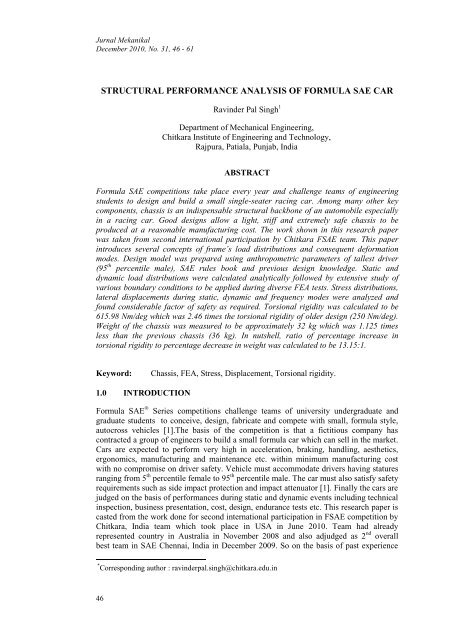
STRUCTURAL PERFORMANCE ANALYSIS OF FORMULA SAE CAR<br />
Ravinder Pal Singh 1<br />
Department <strong>of</strong> Mechanical Engineering,<br />
Chitkara Institute <strong>of</strong> Engineering and Technology,<br />
Rajpura, Patiala, Punjab, India<br />
ABSTRACT<br />
Formula SAE competitions take place every year and challenge teams <strong>of</strong> engineering<br />
students to design and build a small single-seater racing <strong>car</strong>. Among many other key<br />
components, chassis is an indispensable <strong>structural</strong> backbone <strong>of</strong> an automobile especially<br />
in a racing <strong>car</strong>. Good designs allow a light, stiff and extremely safe chassis to be<br />
produced at a reasonable manufacturing cost. The work shown in this research paper<br />
was taken from second international participation by Chitkara FSAE team. This paper<br />
introduces several concepts <strong>of</strong> frame’s load distributions and consequent deformation<br />
modes. Design model was prepared using anthropometric parameters <strong>of</strong> tallest driver<br />
(95 th percentile male), SAE rules book and previous design knowledge. Static and<br />
dynamic load distributions were calculated analytically followed by extensive study <strong>of</strong><br />
various boundary conditions to be applied during diverse FEA tests. Stress distributions,<br />
lateral displacements during static, dynamic and frequency modes were analyzed and<br />
found considerable factor <strong>of</strong> safety as required. Torsional rigidity was calculated to be<br />
615.98 Nm/deg which was 2.46 times the torsional rigidity <strong>of</strong> older design (250 Nm/deg).<br />
Weight <strong>of</strong> the chassis was measured to be approximately 32 kg which was 1.125 times<br />
less than the previous chassis (36 kg). In nutshell, ratio <strong>of</strong> percentage increase in<br />
torsional rigidity to percentage decrease in weight was calculated to be 13.15:1.<br />
Keyword: Chassis, FEA, Stress, Displacement, Torsional rigidity.<br />
1.0 INTRODUCTION<br />
Formula SAE ® Series competitions challenge teams <strong>of</strong> university undergraduate and<br />
graduate students to conceive, design, fabricate and compete with small, <strong>formula</strong> style,<br />
autocross vehicles [1].The basis <strong>of</strong> the competition is that a fictitious company has<br />
contracted a group <strong>of</strong> engineers to build a small <strong>formula</strong> <strong>car</strong> which can sell in the market.<br />
Cars are expected to perform very high in acceleration, braking, handling, aesthetics,<br />
ergonomics, manufacturing and maintenance etc. within minimum manufacturing cost<br />
with no compromise on driver safety. Vehicle must accommodate drivers having statures<br />
ranging from 5 th percentile female to 95 th percentile male. The <strong>car</strong> must also satisfy safety<br />
requirements such as side impact protection and impact attenuator [1]. Finally the <strong>car</strong>s are<br />
judged on the basis <strong>of</strong> <strong>performance</strong>s during static and dynamic events including technical<br />
inspection, business presentation, cost, design, endurance tests etc. This research paper is<br />
casted from the work done for second international participation in FSAE competition by<br />
Chitkara, India team which took place in USA in June 2010. Team had already<br />
represented country in Australia in November 2008 and also adjudged as 2 nd overall<br />
best team in SAE Chennai, India in December 2009. So on the basis <strong>of</strong> past experience<br />
* Corresponding author : ravinderpal.singh@chitkara.edu.in
<strong>Jurnal</strong> <strong>Mekanikal</strong>, December 2010<br />
and knowledge, whole <strong>of</strong> the <strong>car</strong> was re-modeled and re-fabricated for international<br />
participation in USA as per the SAE rules. This time reduction <strong>of</strong> chassis weight<br />
minimally by 10% using new materials and efficient design was decided as one <strong>of</strong> the<br />
main objective <strong>of</strong> <strong>car</strong> development. New materials were deemed to use to widen the<br />
structure’s strength and re-modeled the design to inculcate more driver comfort, safety,<br />
structure triangulation and reduced inertial properties etc. The work started from the<br />
review <strong>of</strong> technical reports <strong>of</strong> several winning universities. Their main points regarding<br />
materials, design and load estimations were noted and discussed. Along with it,<br />
orthographic drawings, finite element <strong>analysis</strong> (FEA) reports <strong>of</strong> existing <strong>car</strong>’s chassis<br />
were also brainstormed and reasons <strong>of</strong> high stresses and displacements were tried to<br />
discover. Modes <strong>of</strong> load distribution and their deformation concepts were taken <strong>car</strong>e <strong>of</strong><br />
from various reference books. Some <strong>of</strong> the concepts are also enunciated in this paper to<br />
help other universities while preparing the design <strong>of</strong> their <strong>car</strong>.<br />
2.0 CHASSIS LOADING<br />
Frame is defined as a fabricated <strong>structural</strong> assembly that supports all functional vehicle<br />
systems. This assembly may be a single welded structure, multiple welded structures or a<br />
combination <strong>of</strong> composite and welded structures [1]. Depending upon application <strong>of</strong> loads<br />
and their direction, chassis is deformed in respective manner briefed as follows [2]:<br />
i. Longitudinal Torsion<br />
ii. Vertical Bending<br />
iii. Lateral Bending<br />
iv. Horizontal Lozenging<br />
2.1) Longitudinal Torsion<br />
Figure 1: Longitudinal Torsion [3]<br />
Application <strong>of</strong> equal and opposite forces act at a certain distance from an axis tends to<br />
rotate the body about the same axis. Automobiles also experience torsion while moving<br />
on road subjected to forces <strong>of</strong> different magnitudes acting on one or two oppositely<br />
opposed corners <strong>of</strong> the <strong>car</strong>s as shown in Figure 1. The frame can be thought as a torsion<br />
spring connecting the two ends where suspension loads act [2]. Torsional loading and<br />
resultant momentary elastic or permanent plastic deformation and subsequent unwanted<br />
deflections <strong>of</strong> suspension springs can affect the handling as well as <strong>performance</strong> <strong>of</strong> <strong>car</strong>.<br />
The resistance to torsional deformation is called as stiffness and it is expressed in<br />
Nm/degree in SI units. Torsional rigidity is a foremost and primary determinant <strong>of</strong> frame<br />
<strong>performance</strong> <strong>of</strong> <strong>car</strong>s.<br />
47
<strong>Jurnal</strong> <strong>Mekanikal</strong>, December 2010<br />
2.2 Vertical Bending<br />
48<br />
Figure 2: Vertical Bending [3]<br />
Weight <strong>of</strong> driver, engine, drive-train, radiator and shell etc. under an effect <strong>of</strong><br />
gravity produce sag in the frame as shown in Figure 2. Frame is assumed to act as simply<br />
supported beam and four wheels as supports tend to produce reactions vertically upward<br />
at the axles. Vertical dynamic forces due to acceleration/deceleration further increase the<br />
vertical deflections, hence stresses in chassis.<br />
2.3 Lateral Bending<br />
Lateral bending deformation occurs mainly due to the centrifugal forces caused during<br />
cornering and wind forces to some extent. Lateral forces act along the length <strong>of</strong> chassis<br />
and is resisted by axles, tires and frame members viz. hoops, side impact members and<br />
diagonal hoops etc as shown in Figure 3.<br />
Figure 3: Lateral Bending [3]<br />
2.4 Horizontal Lozenging<br />
This deformation is caused by forward and backward forces applied at opposite wheels<br />
[3]. These forces may be caused by vertical variations in the pavement or the reaction<br />
from the road driving the <strong>car</strong> forward. These forces tend to distort the frame into a<br />
parallelogram shape as shown in the Figure 4. The magnitude <strong>of</strong> these loads changes with<br />
the operating mode <strong>of</strong> the <strong>car</strong>.
Figure 4: Horizontal Lozenging [3]<br />
<strong>Jurnal</strong> <strong>Mekanikal</strong>, December 2010<br />
It is generally thought that if torsional and vertical bending stiffness is<br />
satisfactory, then the chassis structure is expected to perform well. But torsional stiffness<br />
is given more weight-age as the total cornering traction is the function <strong>of</strong> lateral weight<br />
transfers [2].<br />
3.0 LOAD ESTIMATION<br />
After literature review, it was brought in view that normally FSAE <strong>car</strong> parts are designed<br />
to withstand 3.5 g bump, 1.5 g braking and 1.5 g lateral forces [4]. These loads have to be<br />
considered individually and combined. Determination <strong>of</strong> magnitudes, types and center <strong>of</strong><br />
gravity (cg) <strong>of</strong> loads is obligatory for optimum frame structure which is likewise a<br />
repetitive task. An understanding <strong>of</strong> different loads in respective directions is shown in<br />
Figure 5 in reference to Formula <strong>car</strong>s.<br />
Figure 5: Forces acting on a <strong>formula</strong> one <strong>car</strong> [7]<br />
To estimate an individual and total load <strong>of</strong> various components and <strong>car</strong> as a<br />
whole, a block diagram showing estimated position <strong>of</strong> components was created as shown<br />
in Figure 6. This schematic diagram simplified the understanding <strong>of</strong> different loads and<br />
their respective positions.<br />
49
<strong>Jurnal</strong> <strong>Mekanikal</strong>, December 2010<br />
50<br />
Figure 6: Car side view with all parts<br />
Table 1: Approximate masses <strong>of</strong> main components<br />
C.G Components Mass (kg)<br />
1 Driver 80<br />
2 Engine 70<br />
3 Drive-train 20<br />
4 Steering 10<br />
5 Battery 03<br />
6 Chassis<br />
32 (Later calculated from<br />
mass properties)<br />
Total 215<br />
To consider mass <strong>of</strong> other components also, estimated mass <strong>of</strong> 250 kg was<br />
considered instead <strong>of</strong> 215 kg. This includes mass <strong>of</strong> wishbones (front and rear), petrol<br />
tank as well as radiator etc. Different forces viz. cornering, acceleration forces were<br />
computed from masses using Newton’s second law <strong>of</strong> motion.<br />
4.0 MATERIAL SELECTION<br />
After load approximation, next step was the selection <strong>of</strong> material to construct a chassis.<br />
Availability is one <strong>of</strong> the factors which dominate the material selection process. Working<br />
on this single aspect, list <strong>of</strong> different desirable and available materials was prepared. Steel<br />
and aluminum alloys are always the choice <strong>of</strong> most <strong>of</strong> the teams. After reviewing<br />
mechanical properties, availability, cost and other significant factors, following material<br />
was selected.<br />
Table 2: Mechanical Properties <strong>of</strong> Chassis Material<br />
STEEL GRADE: IS 3074<br />
S.No. Properties Values<br />
1 Young’s modulus 2e+011 N/m 2<br />
2 Poisson ratio 0.266<br />
3 Density 7860 kg/m 3<br />
4 Yield Strength 3.73e+008 N/m 2
5.0 SOLID MODELLING<br />
<strong>Jurnal</strong> <strong>Mekanikal</strong>, December 2010<br />
After load approximation and material selection, preparing CAD model <strong>of</strong> chassis was a<br />
next step. Based on past design knowledge, anthropometric data <strong>of</strong> tallest driver was<br />
taken and previous 3-D chassis model was modified. CATIA V5 s<strong>of</strong>tware tool was used<br />
for designing as well as Finite Element analyses (FEA). SAE rules were taken <strong>car</strong>e <strong>of</strong><br />
while designing. Mankin was created in same s<strong>of</strong>tware on the basis <strong>of</strong> anthropometric<br />
data and checked it under different realistic conditions to suit chassis design. It was a two<br />
way process as firstly creating model and checking clashes with mankin and vice versa<br />
was a repetitive task. After much iteration, CAD model was proposed as shown in Figure<br />
7.<br />
Figure 7: 3D Chassis Structure<br />
Whole <strong>of</strong> the chassis model was made up <strong>of</strong> round hollow cross section tubes <strong>of</strong><br />
IS 3074 steel throughout chassis. Tubes <strong>of</strong> two different sizes were used in the design.<br />
Whole <strong>of</strong> the structure comprises <strong>of</strong> tube 1” (outer diameter) and 1.6 mm wall thickness<br />
except main hoop and front hoop. Both (front and main) hoops are made up <strong>of</strong> 1” (Outer<br />
diameter) and 2.5 mm wall thickness as shown in red color in Figure 7. Mass properties<br />
showed the mass <strong>of</strong> chassis was to be 32 kg.<br />
6.0 FINITE ELEMENT ANALYSIS (FEA)<br />
Structure designing was followed by its testing and consequent validity. To determine the<br />
stiffness <strong>of</strong> a proposed frame design before construction, finite element <strong>analysis</strong> could<br />
serve the purpose. While the process <strong>of</strong> solving Finite Element problems is a science,<br />
creating the models is quite an art [2].<br />
Conventionally in FEA, the frame is subdivided into elements. Nodes are placed<br />
where tubes <strong>of</strong> frame join. There are many types <strong>of</strong> elements possible for a structure and<br />
every choice the analyst makes can affect the results. The number, orientation and size <strong>of</strong><br />
elements as well as loads and boundary conditions are all critical to obtain meaningful<br />
values <strong>of</strong> chassis stiffness [2]. Beam elements are normally used to represent tubes. The<br />
assumption made in using beam elements is that the welded tubes have stiffness in<br />
bending and torsion [2]. If a truss or link elements were used, the assumption being made<br />
would be that the connections do not <strong>of</strong>fer substantial resistance to bending or torsion [2].<br />
Another aspect <strong>of</strong> beam elements is the possibility <strong>of</strong> including transverse shearing<br />
effects.<br />
51
<strong>Jurnal</strong> <strong>Mekanikal</strong>, December 2010<br />
While modeling the stiffness contribution from each part <strong>of</strong> the frame, method to<br />
apply the loads and constrain the frame plays significant role for an accurate <strong>analysis</strong>.<br />
Accurate <strong>analysis</strong> means to predict the stiffness <strong>of</strong> frame close to actual stiffness as the<br />
frame operates in real conditions. The problem here has normally been how to constrain<br />
and load a frame, so to receive multiple load inputs from a suspension, while it has been<br />
separated from that suspension and many other such problems. For practical reasons, it is<br />
recommended that the load on the chassis frame, including its own weight should be<br />
applied at the joints (nodes) <strong>of</strong> <strong>structural</strong> members. These point loads were statistically<br />
equivalent to the actual distributed load <strong>car</strong>ried by the vehicle [5].<br />
Another thing to consider while modeling the frame is how to represent an<br />
engine. For the engine, the first step is to locate a node at each position where there is an<br />
engine mount. These mounts then need to be connected to the frame by an element.<br />
Engine was assumed to be very stiff relative to the <strong>car</strong> frame. Thus assuming an engine to<br />
be infinitely rigid, it can be modeled by connecting each engine mount node to every<br />
other engine mount node by a beam element <strong>of</strong> high stiffness.<br />
One <strong>of</strong> the few things that could be done to reduce the number <strong>of</strong> elements was to<br />
replace the engine model with a solid block <strong>of</strong> aluminum connected to the frame by the<br />
engine mounts. As most <strong>of</strong> the parts <strong>of</strong> an engine are made up <strong>of</strong> aluminum alloy, so it<br />
was assumed that an engine as a whole will behave in the similar manner as can be<br />
behaved by a solid block <strong>of</strong> same material. This greatly reduced the complexity <strong>of</strong> the<br />
meshed model and produced satisfactory results. Various elements used in the present<br />
paper to mesh the different parts <strong>of</strong> chassis are shown in Table 3.<br />
52<br />
Table 3: Elements used for meshing<br />
S. No. Element Purpose<br />
1<br />
Linear Tetrahedral<br />
Round hollow tubes <strong>of</strong> frame,<br />
2 Linear Tetrahedral Engine and suspension mounts<br />
Applying static loads on model is comparatively easier than ascertaining a frequency<br />
range at which frame needs to be tested. In idle conditions, the speed range <strong>of</strong> Honda<br />
VFR engine which was used in this project is 12 to 14 revolutions per second. This<br />
translates into excitation frequency range <strong>of</strong> 13-15 Hz. The excitation from transmission<br />
is about 0-100 Hz. [6]. The main excitation is at low speeds, when the vehicle is in the<br />
first gear. At higher gear or speed, the excitation to the chassis is much less [5]. The<br />
natural frequency <strong>of</strong> the vehicle chassis should not coincide with the frequency range <strong>of</strong><br />
the axles because this can cause resonance which may give rise to high deflection and<br />
stresses and poor ride comfort. Excitation from the road is the main disturbance to the<br />
chassis when the vehicle travels along the road. In practice, the road excitation has typical<br />
values varying from 0 to 100 Hz [5]. At high cruising speed, the excitation is about 9000<br />
rpm or 150 Hz. Various boundary conditions and force/moments applied during various<br />
FEA tests are enunciated in the Table 4
S.<br />
No.<br />
1<br />
2<br />
3<br />
4<br />
5<br />
Table 4: Boundary conditions used during various tests<br />
Test Boundary condition Force Moments<br />
Static Shear<br />
Static overall<br />
bending<br />
Static<br />
torsional<br />
loading<br />
Clamp- rear<br />
suspension mounts<br />
Clamp- front and rear<br />
suspension mounts<br />
Clamp- rear<br />
suspension mounts<br />
7.0) RESULTS AND DISCUSSION<br />
<strong>Jurnal</strong> <strong>Mekanikal</strong>, December 2010<br />
Downward force at front<br />
bulkhead<br />
Uniformly distributed<br />
loading<br />
Clockwise Moment at<br />
bulkhead side<br />
7.1 Static Shear<br />
In static shear, it is assumed that frame acts like a cantilever beam and its one end is made<br />
fixed and other end is subjected to vertical downward force as shown in Figure 8. Shear<br />
force and bending moment diagrams were drawn and maximum bending moment was<br />
calculated analytically at the fixed end <strong>of</strong> frame. Blue color shows clamping and yellow<br />
color shows vertically downward forces acting at the front bulkhead as shown in figure 8.<br />
The rear suspension mounts were clamped in this case. Force <strong>of</strong> 1440 N was applied at<br />
the bulkhead which is the sum <strong>of</strong> weight <strong>of</strong> impact attenuator, driver legs and steering<br />
weight etc. Maximum bending moment <strong>of</strong> 2081 Nm calculated to act about the Y-axis.<br />
Clamp<br />
Acceleration<br />
Analysis<br />
Frequency<br />
<strong>analysis</strong><br />
Clamp- front and rear<br />
suspension mounts<br />
Clamp- front and rear<br />
suspension mounts<br />
Force applied towards<br />
rear<br />
Frequency range- 69.12<br />
Hz to 204.79 Hz<br />
Figure 8: Boundary conditions during static shear<br />
Point Load<br />
53
<strong>Jurnal</strong> <strong>Mekanikal</strong>, December 2010<br />
54<br />
Figure 9: Von Misses stresses during static shearing<br />
Results showed that maximum Von Misses stress was to be 1.17x10 8 N/m 2 .<br />
Maximum strain energy (Pro<strong>of</strong> resilience) capability <strong>of</strong> 4.345 Joules was observed from<br />
this <strong>analysis</strong>. Elements in red color show the maximum stress areas and corresponding<br />
maximum stress is shown in red color in stress tree in the left <strong>of</strong> Figure 9.<br />
7.2 Static Vertical Bending<br />
Clamp<br />
Point Load<br />
Figure 10: Boundary conditions during static vertical bending<br />
Both front and rear suspension mounts were clamped and vertically downward<br />
point forces <strong>of</strong> 1550 N were applied equally in driver cabin, engine bay and drive-train<br />
section as shown in Figure 10. Frame is assumed to be a fixed beam with both ends<br />
clamped and subjected to point shear forces acting downward. Bending moment and<br />
shear force diagrams were drawn and values were calculated analytically. Blue color<br />
shows the clamping restraint and yellow color shows the point forces acting downward.
<strong>Jurnal</strong> <strong>Mekanikal</strong>, December 2010<br />
Figure 11: Von Misses stresses during static vertical bending<br />
Maximum bending moment <strong>of</strong> 4.482 Nm about Y-axis with maximum vertical<br />
downward displacement <strong>of</strong> 0.369 mm was noted. Maximum Von Misses stress <strong>of</strong><br />
2.77x10 7 N/m 2 was observed at one or two places shown in red color in Figure 11. Most<br />
<strong>of</strong> the areas throughout chassis were observed to be subjected to minimum value <strong>of</strong> stress<br />
as shown in stress distribution tree in Figure 11. Maximum deflection was observed in the<br />
center <strong>of</strong> driver cabin floor and noted down its position to strengthen it. Strain energy <strong>of</strong><br />
0.087 J was noted.<br />
7.3 Lateral Bending<br />
Figure 12: Application <strong>of</strong> lateral forces acting on roll hoop in driver cabin<br />
Clamping restraint was applied at both front and rear suspension mounts as in<br />
previous cases. Lateral cornering point forces <strong>of</strong> 2325 N (Sum <strong>of</strong> engine and driver<br />
forces) was applied on side impact bracings <strong>of</strong> driver cabin, engine mounts and drivetrain<br />
side braces. Yellow color arrows are depicted application <strong>of</strong> forces acting outwards.<br />
Figure 13: Von Mises stresses during lateral bending<br />
55
<strong>Jurnal</strong> <strong>Mekanikal</strong>, December 2010<br />
Maximum principal stress <strong>of</strong> 1.48x10 7 N/m 2 (Figure 13) was observed with<br />
maximum translational displacement <strong>of</strong> 0.142 mm after post processing which are within<br />
the permissible limit <strong>of</strong> stresses. Strain energy <strong>of</strong> 0.015 J was observed.<br />
7.4 Static Torsional Loading<br />
56<br />
Clamp Torque<br />
Figure 14: Boundary conditions during torsion test<br />
Torsional rigidity test is one <strong>of</strong> the most important tests which validates/rejects<br />
the chassis structure. In this case, chassis is assumed to act as a cantilever with one end<br />
fixed and other end free and subjected to torque about its longitudinal axis as shown in<br />
Figure 14. A chassis should be able to resist angular deformation and resultant shear<br />
stresses. Again clamping is shown by the blue color and clockwise torque is shown in<br />
yellow color. Clockwise moment 316 Nm about longitudinal X-axis was applied.<br />
Figure 15: Von Misses stresses during torsion<br />
Uniform stress <strong>of</strong> 5.02x10 7 N/m 2 (Figure 15) was observed with maximum stress<br />
<strong>of</strong> 01x10 8 N/m 2 at few points as shown in red color. Maximum translational displacement<br />
<strong>of</strong> 2.24 mm was noted in front bulkhead supports and lowers side impact members.<br />
Almost all other areas were found to be safe with approximately no stress and<br />
displacement. Strain energy <strong>of</strong> 2.303 J was observed from the results.
7.5 Accelaration Test<br />
Acceleration<br />
Forces<br />
Figure 16: Boundary conditions during acceleration test<br />
<strong>Jurnal</strong> <strong>Mekanikal</strong>, December 2010<br />
Point Load<br />
Due to inertia effect, acceleration forces tend to act in opposite direction to the<br />
motion <strong>of</strong> body. Forces due to acceleration were calculated considering masses <strong>of</strong> driver<br />
(80 kg) and engine (70 kg) respectively. Engine acceleration <strong>of</strong> 6.61 m/s 2 was taken from<br />
the manual <strong>of</strong> Honda VFR engine to be used in this vehicle and calculated an acceleration<br />
force using Newton second law <strong>of</strong> motion (F=m*a). Total acceleration force <strong>of</strong> 992.2 N<br />
was applied on the structure in backward direction shown in thick yellow color arrows in<br />
Figure 16. Load <strong>of</strong> 1550 N was applied throughout in driver cabin, engine bay and drivetrain<br />
section as to simulate realistic conditions.<br />
Figure 17: Von Misses stresses during acceleration<br />
Clamp<br />
Chassis experienced maximum bending moment <strong>of</strong> 171.4 Nm about Y-axis<br />
(anticlockwise) at cross-sections shown in red color. Whole <strong>of</strong> the chassis was found to<br />
be within permissible stress limit with maximum stress was observed to be 2.67x10 7 N/m 2<br />
as shown in red color in Figure 17. Strain energy <strong>of</strong> 0.102 J was given by the FEA results.<br />
7.6 Frequency Test<br />
Engine is a source <strong>of</strong> vibrations in any vehicle. Chassis as with any structure has an<br />
infinite number <strong>of</strong> resonant frequencies [8]. A resonant frequency, also known as natural<br />
frequency, is a preferred frequency <strong>of</strong> vibration and results when the inertial and stiffness<br />
forces cancel. For each <strong>of</strong> the infinite natural frequencies <strong>of</strong> vibrations which exist, a<br />
different shape that the chassis deform during vibration also exists [8]. The deformed<br />
shape that chassis will vibrate is also known as modes <strong>of</strong> vibration [8]. So, frequency<br />
57
<strong>Jurnal</strong> <strong>Mekanikal</strong>, December 2010<br />
<strong>analysis</strong> is mandatory to check <strong>structural</strong> behavior during a set range <strong>of</strong><br />
frequencies. Indirect actuated suspension system was used at front and rear <strong>of</strong> the vehicle.<br />
A component called as rocker used to transmit the forces and motion from the tires<br />
through tie rods to springs <strong>of</strong> shock absorbers. The rocker was clamped and hinged with<br />
the chassis. Hence chassis was clamped at both front and rear due to suspension<br />
construction with no external load applied. Only <strong>structural</strong> mass was taken into account<br />
for <strong>analysis</strong> as shown in Figure 18.<br />
58<br />
Figure 18: Boundary conditions during frequency test<br />
Clamp<br />
Figure 19: Von Misses stresses and modal <strong>analysis</strong> during frequency test<br />
S<strong>of</strong>tware checked the structure from 69 Hz to 205 Hz automatically. No stresses<br />
were observed below 156.86 Hz and chassis was found to be safe (high factor <strong>of</strong> safety).<br />
At frequency <strong>of</strong> 156.86 Hz, 5.53x10 10 N/m 2 (elements shown in red color in figure 19)<br />
was observed to be more than the permissible stress <strong>of</strong> material (3.73e+008 N/m 2 ).<br />
Maximum translational displacement <strong>of</strong> 562 mm was noted down at this frequency. Of<br />
the infinite modes <strong>of</strong> vibration that exist on the frame structure, only the lowest<br />
frequencies are <strong>of</strong> interest [8]. The lower modes <strong>of</strong> vibration maximize the kinetic energy<br />
and maximize the strain energy, while the high modes act in an opposite manner [8]. This<br />
means that the s<strong>of</strong>t and stiff parts <strong>of</strong> chassis will be apparent in the low and high modes <strong>of</strong><br />
vibrations respectively. Therefore it is worth to note that at lower frequencies (below<br />
156.86 Hz), no considerable stress was found and chassis was assumed to be safe with<br />
considerable factor <strong>of</strong> safety. The most affected region was the main hoop and main hoop<br />
bracings with maximum stress and displacement.
S. No.<br />
1<br />
2<br />
3<br />
4<br />
5<br />
6<br />
Table 5: Von Misses stresses and Factor <strong>of</strong> Safety<br />
Test<br />
Static Shear<br />
Static overall bending<br />
Lateral Bending<br />
Static torsional loading<br />
Acceleration test<br />
Frequency <strong>analysis</strong><br />
Von Misses Stress (N/m 2 )<br />
1.17*108<br />
2.27*107<br />
1.48*107<br />
1*108<br />
2.67x10⁷<br />
5.53*10 10 (156.86 Hz)<br />
<strong>Jurnal</strong> <strong>Mekanikal</strong>, December 2010<br />
FOS<br />
3.18<br />
16.41<br />
25.25<br />
3.73<br />
13.97<br />
By dividing yield stress (3.73e+008 N/m 2 ) <strong>of</strong> chassis material with maximum<br />
Von Misses stresses induced in frame, factor <strong>of</strong> safety was calculated as shown in table 5.<br />
Considerable factor <strong>of</strong> safety was observed in all static (shear, bending and torsional test)<br />
boundary conditions. Chassis was found to exhibit high factor <strong>of</strong> safety during dynamic<br />
viz. acceleration test. Frame behavior was analyzed in frequency range <strong>of</strong> 69.12 to<br />
204.793 Hz and observed maximum deformation (stress and deflection), more than the<br />
yield stress <strong>of</strong> frame material at a frequency <strong>of</strong> 156.86 Hz. Below 156.86 Hz, chassis was<br />
observed to be safe and experienced stress very small than the strength <strong>of</strong> material.<br />
So, 156.86 Hz can be considered as threshold value for proposed chassis. Chassis was<br />
found to have highest factor <strong>of</strong> safety in lateral bending (25.25) followed by static<br />
bending (16.41) and dynamic acceleration test (13.97) respectively.<br />
Factor <strong>of</strong> safety was noted to be 3.73 in torsional loading mode which represents<br />
the stiff nature <strong>of</strong> frame. An ideal chassis is one that has high stiffness; with low weight<br />
and cost. If there is considerable twisting, the chassis vibrates, complicating the system <strong>of</strong><br />
the vehicle and sacrificing the handling <strong>performance</strong> [8]. The chassis that flexes is more<br />
susceptible to fatigue and subsequent failure, and “suspension compliance may be<br />
increased or decreased by bending or twisting <strong>of</strong> the chassis [9]. Also if a chassis is well<br />
designed to handle torsional loads, bending should not be an issue [9]. The torsional<br />
rigidity can be calculated by finding the torque applied to the frame and dividing by the<br />
angular deflection. The actual calculation is done as follows, with the figure 20 showing a<br />
view looking from the front <strong>of</strong> the suspension bay.<br />
K=R/Ө (1)<br />
K= (F*L)/tan-1[(Δy1+Δy2)/2L] (2)<br />
where K = Torsional Stiffness<br />
T = Torque<br />
Ө = Angular deformation<br />
F = Shear Force<br />
y1, y2= Translational displacement<br />
00<br />
59
<strong>Jurnal</strong> <strong>Mekanikal</strong>, December 2010<br />
60<br />
Figure 20: Front suspension bay testing loads<br />
Force applied (F) = 1264 Nm<br />
y1= y2 = 2.24 mm = 0.00224m<br />
L= 0.250 m<br />
K= (1264*0.250)/tan -1 [(0.00224+0.00224)/2*0.250] = 615.98 Nm/deg<br />
Torsional rigidity <strong>of</strong> previous design was calculated to be 250 Nm/deg [11] which<br />
was an indicator <strong>of</strong> moderate stiffness and hence needed to be improved following<br />
changes in design and material. The torsional stiffness <strong>of</strong> present design was calculated to<br />
be 615.98 Nm/deg as calculated above which shows significant increase in stiffness in<br />
present model by 2.46 times than the older design. Deakin et al concluded that a Formula<br />
SAE racer, which has a total suspension roll stiffness <strong>of</strong> 500–1500 Nm/degree, requires<br />
chassis stiffness between 300 and 1000 Nm/degree to enable the handling to be tuned<br />
[10]. Torsional rigidity <strong>of</strong> University <strong>of</strong> Southern Queensland (USQ) 2004 SAE <strong>car</strong><br />
experienced torsional rigidity <strong>of</strong> 214 Nm/degree and appeared to drive reasonably well,<br />
apart from the under-steer and other minor construction matters [10]. Increase in chassis<br />
stiffness in present work owes to good <strong>structural</strong> design having more triangulation and <strong>of</strong><br />
course higher yield strength <strong>of</strong> IS 3074.<br />
8.0 CONCLUSIONS<br />
The dominant characteristic <strong>of</strong> <strong>structural</strong> behavior viz. torsional rigidity increased by 2.46<br />
times with an average value <strong>of</strong> 615.98 Nm/deg without compromising on weight. Weight<br />
<strong>of</strong> chassis was observed to decrease by 11.11% with approximate value <strong>of</strong> 32 kg as<br />
compared to weight <strong>of</strong> older chassis frame. Stress distributions were found to be even and<br />
less than the yield strength <strong>of</strong> material (3.73e+008 N/m 2 ). Chassis was found to be safe<br />
significantly in static (bending) and dynamic (acceleration) modes with stress values<br />
noticeably less than the yield strength. Critical value <strong>of</strong> stress was found to be 5.53x10 10<br />
N/m 2 at a frequency <strong>of</strong> 156.86 Hz. Although below this frequency, chassis was found to<br />
be safe and exhibited almost no stress. Dynamometer testing <strong>of</strong> previous <strong>car</strong> at<br />
approximate 9000 rpm with speed <strong>of</strong> 90 km/h, the maximum vibration frequency was<br />
noted to be not more than 100 Hz. So, it was expected that vibration range under same<br />
conditions will either remain same or decrease for the present design model. Hence<br />
chassis was expected to perform well in motion also.
REFERENCES<br />
<strong>Jurnal</strong> <strong>Mekanikal</strong>, December 2010<br />
1. 2010 Formula SAE® Rules, SAE International, USA.<br />
2. Riley, W.B., George, A.R., 2002. Design, Analysis and Testing <strong>of</strong> Formula SAE<br />
Race Car Chassis, SAE paper 2002-01-3300, Motorsports Engineering<br />
Conference and proceedings.<br />
3. Horizontal Lozenging, Retrieved from http://rileydynamics.com/meng%20web/sec2.htm.<br />
on 17 June, 2010 1:10:37 GMT.<br />
4. Milliken, William F., Milliken, Douglas L., 1997. Race Car Vehicle Dynamics,<br />
Society <strong>of</strong> Automotive Engineers.<br />
5. Fui, T.H., Rahman, R.A., 2007. Statics and Dynamics Structural Analysis <strong>of</strong> a 4.5<br />
Ton Structural Analysis, <strong>Jurnal</strong> <strong>Mekanikal</strong>, 24, 56-67.<br />
6. Johansson, I., Edlund, S., 1993. Optimization <strong>of</strong> Vehicle Dynamics in Trucks by<br />
Use <strong>of</strong> Full Vehicle FE-Models, Göteborg, Sweden, Department <strong>of</strong> Vehicle<br />
Dynamics & Chassis Technology, Volvo Truck Corporation.<br />
7. O’Neill, A.M., 2005. Chassis Design for SAE Racer, University <strong>of</strong> Southern<br />
Queensland.<br />
8. Ryan, A. 2008. Formula SAE Race Car Analysis: Simulation and Testing <strong>of</strong> the<br />
Engine as a <strong>structural</strong> member, Retrieved from<br />
http://www.fisita.com/students/congress/sc08papers/f2008sc005.pdf on 06 June,<br />
2010 03:40:37 GMT.<br />
9. William F., Miliken and Douglas L. 1995. Race Car Vehicle Dynamics, Society<br />
<strong>of</strong> Automotive Engineers Inc., 673-667.<br />
10. Deakin, A., Crolla, D., Ramirez, JP, and Hanley, R. 2004. The Effect <strong>of</strong> Chassis<br />
Stiffening on Race Car Handling Balance, Racing Chassis and Suspension<br />
Design, Society <strong>of</strong> Automotive Engineers, Warrendale, PA.<br />
11. Singh, R.P. and Kaur, T., 2009. Designing and fabrication <strong>of</strong> <strong>formula</strong> SAE<br />
vehicle (Chassis), National Conference on Innovative developments in<br />
engineering applications, Bhai Gurdas Institute <strong>of</strong> Engineering and Technology,<br />
Sangrur, Punjab, India, 265-271.<br />
61