Rear I/O Module • CU7-RS485 - Ekf
Rear I/O Module • CU7-RS485 - Ekf
Rear I/O Module • CU7-RS485 - Ekf

You also want an ePaper? Increase the reach of your titles
YUMPU automatically turns print PDFs into web optimized ePapers that Google loves.
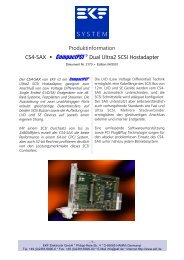
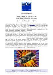
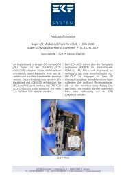
Product Information<br />
<strong>Rear</strong> I/O <strong>Module</strong> <strong>•</strong> <strong>CU7</strong>-<strong>RS485</strong><br />
Document No. 2685 <strong>•</strong> Edition 26 November 2010<br />
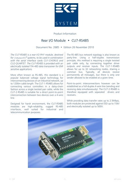
The <strong>CU7</strong>-<strong>RS485</strong> is a rear-I/O PHY module, destined<br />
for CompactPCI ® systems, to be used in combination<br />
with the serial interface cards CU1-CHORUS and<br />
CU2-QUARTET. The <strong>CU7</strong>-<strong>RS485</strong> is provided with an<br />
electrically isolated TIA-485 data transceiver for EMI<br />
sensitive applications.<br />
More often known as RS-485, this standard is a<br />
popular balanced voltage signal technology for<br />
interconnecting devices on an industrial network, up<br />
to 1200m cable length. The <strong>CU7</strong>-1-<strong>RS485</strong> allows for<br />
connecting various controllers in a daisy-chain<br />
fashion across a single twisted pair cable, while the<br />
<strong>CU7</strong>-2-<strong>RS485</strong> is suitable for a direct point-to-point<br />
interconnection between two devices over a 4-wire<br />
line.<br />
Designed for harsh environment, the <strong>CU7</strong>-<strong>RS485</strong><br />
modules are high-reliability, rugged RS-485<br />
interfaces, well suited for industrial and<br />
telecommunication purposes.<br />
The RS-485 bus network topology is also known as<br />
party-line. Using a half-duplex transmission<br />
principle, this method is requiring a single twisted<br />
pair cable only, by connecting together driver<br />
outputs and receiver inputs. The <strong>CU7</strong>-1-<strong>RS485</strong><br />
allows for up to 32 networking nodes, sharing a<br />
common bus. Typically, all devices receive<br />
permanently all messages, but there is only one<br />
sender allowed to be enabled at a given time.<br />
Point-to-point interconnections however can be<br />
established as a full-duplex 4-wire line (sending and<br />
receiving data simultaneously). The <strong>CU7</strong>-2-<strong>RS485</strong> is<br />
therefore equipped with separated drivers and<br />
receivers.<br />
While providing data transfer rates up to 2.5Mbps,<br />
both modules are protected against ESD up to 15kV<br />
and electrically isolated up to 500V.<br />
© EKF -1- ekf.com
<strong>CU7</strong>-<strong>RS485</strong> <strong>•</strong> <strong>Rear</strong>-I/O Transceiver <strong>Module</strong><br />
Technical Feature Summary <strong>CU7</strong>-<strong>RS485</strong><br />
Form Factor <strong>Rear</strong>-I/O <strong>Module</strong> (60x31mm 2 )<br />
Function PHY Transceiver RS-485 (EIA/TIA-485-A)<br />
Chip Maxim MAX1480EA (<strong>CU7</strong>-1-<strong>RS485</strong>) or MAX1490EA (<strong>CU7</strong>-2-<strong>RS485</strong>),<br />
electrically isolated<br />
RS-485 Interface<br />
<strong>CU7</strong>-1-<strong>RS485</strong><br />
RS-485 Interface<br />
<strong>CU7</strong>-2-<strong>RS485</strong><br />
2-Wire line TxD/RxD, driver and receiver connected, operation mode halfduplex,<br />
the transmitter (driver) is enabled by signal RTS, receiver has a<br />
fail-safe feature if the input is open circuit, external connector D-Sub 9pos.<br />
male<br />
4-Wire line TxD/RxD, driver and receiver not connected, operation mode<br />
full-duplex, the transmitter (driver) is permanently enabled, receiver has a<br />
fail-safe feature if the input is open circuit, external connector D-Sub 9pos.<br />
male<br />
Data Transfer Rate 2.5Mbps max. (<strong>CU7</strong>-1-<strong>RS485</strong>), 2 x 2.5Mbps max. (<strong>CU7</strong>-2-<strong>RS485</strong>)<br />
ESD Protection ±15kV (Human Body Model)<br />
Isolation Voltage ±500V DC max.<br />
Failure Protection Short-circuit current limited, protected against excessive power by<br />
thermal shutdown<br />
Internal Connector 2mm male metric connector 10-pos., suitable for flat ribbon cable<br />
harness to the CU9-BASE<br />
Power Requirements +5V 0.3A max.<br />
Temperature<br />
Humidity<br />
Operating temperature 0-70°C (extended temperature range on request)<br />
Relative humidity 5-90%, non-condensing<br />
Technical specifications are subject to change without further notification<br />
© EKF -2- ekf.com
<strong>CU7</strong>-<strong>RS485</strong> <strong>•</strong> <strong>Rear</strong>-I/O Transceiver <strong>Module</strong><br />
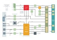
Block Diagram <strong>CU7</strong>-<strong>RS485</strong><br />
© EKF -3- ekf.com
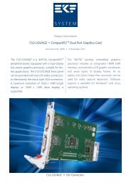
The <strong>CU7</strong>-1-<strong>RS485</strong> and <strong>CU7</strong>-2-<strong>RS485</strong> modules<br />
are intended for use especially with the serial<br />
interface board CU4-SOPRANO. This<br />
CompactPCI ® card has its TTL level serial ports<br />
routed to the backplane connector J2, for rear<br />
I/O by additional PHY (physical layer) modules.<br />
<strong>CU7</strong>-<strong>RS485</strong> <strong>•</strong> <strong>Rear</strong>-I/O Transceiver <strong>Module</strong><br />
CU4-SOPRANO<br />
www.ekf.com/c/ccom/ccom.html<br />
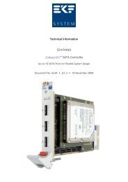
Mounted onto the CPCI backplane from behind,<br />
the additional distribution board CU9-BASE for<br />
up to 16 ports is equipped with metric 2mm<br />
pin headers, mating the flat ribbon cable<br />
assemblies to the particular PHY modules such<br />
as the <strong>CU7</strong>-<strong>RS485</strong>.<br />
© EKF -4- ekf.com
<strong>CU7</strong>-<strong>RS485</strong> <strong>•</strong> <strong>Rear</strong>-I/O Transceiver <strong>Module</strong><br />
CU9-4-BASE<br />
© EKF -5- ekf.com
<strong>CU7</strong>-<strong>RS485</strong> <strong>•</strong> <strong>Rear</strong>-I/O Transceiver <strong>Module</strong><br />
CU9-4-BASE<br />
CU9-BASE (Custom Specific)<br />
© EKF -6- ekf.com
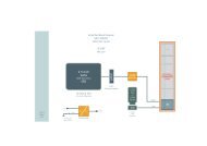
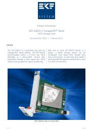
As data rates increase, proper termination on<br />
both ends of the RS-485 bus becomes<br />
important. A popular approach is to use<br />
external termination, having the resistors<br />
located within the shell of the DB9 connectors.<br />
As an alternative, termination resistors can be<br />
stuffed directly on the <strong>CU7</strong>-<strong>RS485</strong> board. Due<br />
to miniaturized SMD components, a properly<br />
equipped working place is highly<br />
recommended.<br />
Typically, the termination resistor value is 120<br />
Ohm or 130 Ohm, ideally matching the twisted<br />
pair cable impedance. When calculating, the<br />
optionally stuffed bias resistors for open-line<br />
fail-safe termination would lie in parallel.<br />
Normally, this effect can be disregarded.<br />
<strong>CU7</strong>-<strong>RS485</strong> <strong>•</strong> <strong>Rear</strong>-I/O Transceiver <strong>Module</strong><br />
R29<br />
H1 1<br />
R30<br />
<strong>CU7</strong>-<strong>RS485</strong> <strong>•</strong> © EKF<br />
MAX1490<br />
MAX1480<br />
Any party-line network must be terminated at<br />
the extreme ends of its bus. Stubs in order to<br />
attach particular nodes are not allowed.<br />
When establishing a point-to-point full-duplex<br />
interconnection, both data directions, receiver<br />
and driver lines, require termination. This<br />
means, in addition to the A/B line also the Y/Z<br />
line must be terminated.<br />
The RS-485 receivers used in the<br />
MAX1480/MAX1490 have an internal built-in<br />
fail-safe feature, so that the resistors R17/R18<br />
and R22/R23 (see figure below) normally should<br />
be not stuffed. If for some reason bias resistors<br />
for open-line fail-safe termination are required,<br />
a nominal value of 750 Ohm or 820 Ohm is<br />
recommended.<br />
R18 R21 R16<br />
R22 R17 R23<br />
DB1<br />
© EKF -7- ekf.com
Is RS-485 a two-wire ore a three-wire system? It is<br />
most definitely a three wire system (four plus one<br />
wire with respect to full-duplex operation). The TIA<br />
standard (ANSI/TIA/EIA-485-A, page 15, A.4.1)<br />
requires the presence of a common return path<br />
between all circuit grounds along the balanced line<br />
for proper operation.<br />
The TIA standard defines a maximum common<br />
mode voltage range from -7V to +12V on the signal<br />
lines A and B, measured against C (common<br />
ground). A TIA/EIA-485 system however with only<br />
two wires A and B (C generator and C receiver<br />
commons not connected) can result in an<br />
unpredictable common mode voltage superimposed<br />
on the interface lines A and B, caused either by<br />
electrostatic charging or electromagnetic<br />
interference.<br />
A 2-wire system often may work though due to idleline<br />
fail-safe resistors at the receiver inputs, which<br />
can be considered as a loosely coupled common<br />
ground. Nevertheless this operation mode cannot<br />
be recommended - what is working flawless in the<br />
laboratory may not work reliable under real<br />
conditions in an industrial environment.<br />
<strong>CU7</strong>-<strong>RS485</strong> <strong>•</strong> <strong>Rear</strong>-I/O Transceiver <strong>Module</strong><br />
External Documents<br />
Where do we get the third wire? Many times the<br />
outer cable shield is used as the third (fifth) wire.<br />
However, EKF recommends to use a two pair cable<br />
(three pairs for full-duplex operation), with one or<br />
both wires of the additional pair as the dedicated<br />
common ground. Connect these additional wires<br />
directly to the pins 3, 6 & 5, 8 of the DB9 connector<br />
for proper grounding.<br />
The optimum cable solution would comprise an<br />
inner shield for each signal twisted pair. The inner<br />
shield can then be used for establishing the<br />
common ground between TIA/EIA-485 nodes<br />
(connect to pins 3, 6 & 5, 8 of the DB9 connector).<br />
An additional outer cable shield, that may cover the<br />
inner signal and ground cable pairs, should be<br />
connected to the pin 1 of the connector (it is<br />
equivalent and sufficient to connect the shield with<br />
the metallic shell of the DB9 connector). This shield<br />
should be grounded at one point only (isolate the<br />
shield at the opposite cable end in order to avoid<br />
any contact with the connector hood).<br />
TIA-485-A ANSI/TIA/EIA-485-A Standard <strong>•</strong> Electrical Characteristics of Generators and Receivers for Use in<br />
Balanced Digital Multipoint Systems <strong>•</strong> http://standardsdocuments.tiaonline.org/tia-485-a.htm<br />
MAX1480EA<br />
MAX1490EA<br />
Article/<br />
Blog<br />
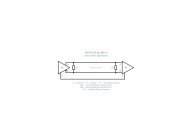
ANSI/TIA/EIA-485-A<br />
Interconnect Application<br />
A<br />
A'<br />
G RT<br />
© EKF <strong>•</strong> ekf.com RT R<br />
B<br />
B'<br />
C<br />
G = Generator <strong>•</strong> R = Receiver <strong>•</strong> RT = Termination Resistor<br />
A/A' = Generator/Receiver Interface Point<br />
B/B' = Generator/Receiver Interface Point<br />
C/C' = Generator/Receiver Common<br />
Datasheet <strong>•</strong> 15kV ESD-Protected, Isolated RS-485/RS-422 Data Interfaces <strong>•</strong> www.maxim-ic.com<br />
<strong>RS485</strong> Cables – Why you need 3 wires for 2 (two) wire <strong>RS485</strong> <strong>•</strong><br />
www.chipkin.com/articles/rs485-cables-why-you-need-3-wires-for-2-two-wire-rs485<br />
© EKF -8- ekf.com<br />
C'
Shield1<br />
Isolated Common Return<br />
A<br />
RS-485 Non-Inverting Input/Output<br />
(<strong>CU7</strong>-1)<br />
RS-485 Non-Inverting Input (<strong>CU7</strong>-2)<br />
Shield2<br />
Isolated Common Return<br />
Y<br />
RS-485 Non-Inverting Output (<strong>CU7</strong>-2)<br />
<strong>CU7</strong>-<strong>RS485</strong> <strong>•</strong> <strong>Rear</strong>-I/O Transceiver <strong>Module</strong><br />
DB1 <strong>•</strong> D-SUB 9-Position Male Connector<br />
6<br />
7<br />
8<br />
9<br />
1 Chassis<br />
Frame GND<br />
H1 <strong>•</strong> Metric Header 2x5 2.0mm<br />
2 B<br />
RS-485 Inverting Input/Output (<strong>CU7</strong>-1)<br />
RS-485 Inverting Input (<strong>CU7</strong>-2)<br />
3 Shield1<br />
Isolated Common Return<br />
4 Z<br />
RS-485 Inverting Output (<strong>CU7</strong>-2)<br />
5 Shield2<br />
Isolated Common Return<br />
+5V 1 2 DSR#<br />
RI# 3 4 RxD<br />
TxD 5 6 DTR#<br />
RTS# 7 8 CTS#<br />
DCD# 9 10 GND<br />
© EKF -9- ekf.com
Ordering No. Short Description<br />
<strong>CU7</strong>-<strong>RS485</strong> <strong>•</strong> <strong>Rear</strong>-I/O Transceiver <strong>Module</strong><br />
Ordering Information<br />
<strong>CU7</strong>-1-<strong>RS485</strong> RS-485/RS-422 <strong>Rear</strong> I/O PHY interface module, 1 port, 2.5Mbps two wire<br />
transmission line (party line), electrically isolated<br />
www.ekf.com/c/ccom/cu7/cu7.html<br />
<strong>CU7</strong>-2-<strong>RS485</strong> RS-485/RS-422 <strong>Rear</strong> I/O PHY interface module, 1 port, 2.5Mbps 4-wire<br />
transmission line (point-to-point), electrically isolated<br />
www.ekf.com/c/ccom/cu7/cu7.html<br />
CU4-2-SOPRANO CompactPCI® quad serial interface, suitable for rear I/O across J2<br />
www.ekf.com/c/ccom/cu4/cu4_e.html<br />
CU9-4-BASE Transition board, interconnection between CU4-SOPRANO (J2) and rear I/O<br />
PHY interface modules, 4 ports, 3U/8HP back panel included<br />
www.ekf.com/c/ccom/cu4/cu4_e.html<br />
EKF Elektronik GmbH<br />
Philipp-Reis-Str. 4<br />
59065 Hamm<br />
Germany<br />
Please refer also to<br />
www.ekf.com/liste/liste_20.html#<strong>CU7</strong><br />
Industrial Computers Made in Germany<br />
boards. systems. solutions.<br />
Phone +49 (0)2381/6890-0<br />
Fax +49 (0)2381/6890-90<br />
Internet www.ekf.com<br />
E-Mail sales@ekf.com