CompactPCI J1 - Ekf
CompactPCI J1 - Ekf
CompactPCI J1 - Ekf

Create successful ePaper yourself
Turn your PDF publications into a flip-book with our unique Google optimized e-Paper software.
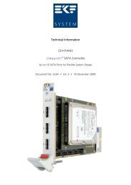
User Guide<br />
CG2-SHANTY • <strong>CompactPCI</strong> ® GPS Receiver<br />
Document No. 3775 • Edition 4<br />
2006-03
User Guide CG2-SHANTY • <strong>CompactPCI</strong> GPS Receiver<br />
Contents<br />
About this Manual ....................................................... 3<br />
Edition History..................................................... 3<br />
Nomenclature ..................................................... 3<br />
Trade Marks ...................................................... 3<br />
Legal Disclaimer - Liability Exclusion ..................................... 3<br />
CG2-SHANTY Features .................................................... 4<br />
Feature Summary .................................................. 4<br />
Short Description................................................... 5<br />
Block Diagram..................................................... 7<br />
Top View Component Assembly ....................................... 8<br />
Front Panel ....................................................... 9<br />
Front Panel Elements ............................................... 10<br />
Strapping Headers ................................................. 10<br />
Connectors & Sockets .............................................. 10<br />
Installation............................................................ 11<br />
Before You Begin.................................................. 11<br />
Warnings .................................................. 11<br />
Caution ................................................... 11<br />
Installing the Board ................................................ 12<br />
Jumper Configuration & Factory Defaults................................ 13<br />
Removing the Board ............................................... 15<br />
EMC Recommendations............................................. 16<br />
Replacement of the Battery .......................................... 17<br />
Technical Reference ..................................................... 18<br />
GPS Receiver Module............................................... 18<br />
General Features............................................. 18<br />
Serial Ports & Protocols ........................................ 19<br />
Auxiliary Power.............................................. 19<br />
Antenna Connector .......................................... 20<br />
Jupiter Module Socket ........................................ 21<br />
Jumper JUTC, Time Mark ...................................... 22<br />
Additional Documentation ..................................... 23<br />
Serial Interfaces ................................................... 24<br />
General Information .......................................... 24<br />
Connector SP2 ......................................... 25<br />
<strong>CompactPCI</strong> ® Interface ............................................. 28<br />
PCI Devices ................................................. 28<br />
System Connector <strong>J1</strong> ......................................... 29<br />
Literature ............................................................. 31<br />
- 2 -<br />
EKF Elektronik GmbH • Philipp-Reis-Str. 4 • 59065 HAMM • Germany<br />
Tel. +49 (0)2381/6890-0 • Fax. +49 (0)2381/6890-90 • E-Mail info@ekf.de • Internet www.ekf.com
About this Manual<br />
User Guide CG2-SHANTY • <strong>CompactPCI</strong> GPS Receiver<br />
This manual describes some technical aspects of the CG2-SHANTY, required for installation and<br />
system integration. It is intended for the experienced user only.<br />
Edition History<br />
Ed. Contents/Changes Author Date<br />
1 User Manual CG2-SHANTY, english, initial edition<br />
(Text #3775, File: cg2_uge.wpd)<br />
2 Added photo CG2-SHANTY<br />
Changed URL<br />
jb 15 September<br />
2005<br />
jb 18 January<br />
2006<br />
3 Changed optional jumper setting jb 2 March 2006<br />
4 Added alternate photos CG2-SHANTY jj 14 March 2006<br />
Nomenclature<br />
Signal names used herein with an attached '#' designate active low lines.<br />
Trade Marks<br />
Some terms used herein are property of their respective owners, e.g.<br />
Pentium, Celeron, Socket 370: ® Intel<br />
<strong>CompactPCI</strong> : ® PICMG<br />
Windows 98, Windows NT, Windows 2000: ® Microsoft<br />
EKF does not claim this list to be complete.<br />
Legal Disclaimer - Liability Exclusion<br />
This manual has been edited as carefully as possible. We apologize for any potential mistake.<br />
Information provided herein is designated exclusively to the proficient user (system integrator,<br />
engineer). EKF can accept no responsibility for any potential damage caused by the use of this<br />
manual.<br />
- 3 -<br />
EKF Elektronik GmbH • Philipp-Reis-Str. 4 • 59065 HAMM • Germany<br />
Tel. +49 (0)2381/6890-0 • Fax. +49 (0)2381/6890-90 • E-Mail info@ekf.de • Internet www.ekf.com
CG2-SHANTY Features<br />
Feature Summary<br />
User Guide CG2-SHANTY • <strong>CompactPCI</strong> GPS Receiver<br />
Feature Summary<br />
Board Form Factor 3U Eurocard (100x160mm 2 ), front panel width 20.3mm (4HP)<br />
Serial Interfaces<br />
SP1 (internally)<br />
SP2 (externally and<br />
internally)<br />
SP3, SP4<br />
(optional usage)<br />
< Device: 16C550 compatible Quad PCI UART Oxford OXmPCI954<br />
asynchronous serial protocol: 1 startbit; 7 or 8 databits; 1 or 2 stopbits;<br />
optional even/odd parity; bitrates up to 15Mbps<br />
< SP1/SP2: typical settings for GPS operation SP1=4800Baud (GPS NMEA-<br />
0183), SP2=9600Baud (DGPS RTCM SC-104)<br />
< SP2 front panel connector: PC compatible D-SUB connector 9-pin male, to<br />
be used either as DGPS input or as universal serial COM port, ESD<br />
protection 15kV, RS-232E transceiver can be disabled by removing jumper<br />
J-SP2 (option)<br />
< SP3/SP4: on-board pin headers suitable for attachment of CU7-RS485 and<br />
CU8-RS232 PHY-modules (option)<br />
< Serial driver software (COM port emulation) available<br />
GPS Receiver < Exchangeable modular 12-channel receiver, chipset SiRFstarII, SMB jack for<br />
1575,42MHz (L1 Band) GPS antenna, supply 0V (passive antenna), +5V,<br />
+3.3V (active antenna) selectable with jumper J-ANT<br />
< Accuracy (horizontal) better than 3m (CEP), 5m (2 dRMS)<br />
< Acquisition performance: hot start 8s, warm start 38s, cold start 45s<br />
< Dead Reckoning capability<br />
< SRAM and RTC data non-volatile buffered by Lithium cell 190mAh<br />
(>10000h)<br />
< Selected NMEA-0183 ASCII messages: latitude, longitude, elevation,<br />
velocity, heading, time, satellite tracking status, command/control<br />
messages (primary serial I/F)<br />
< SiRF binary protocol: raw data (primary serial I/F)<br />
< RTCM ASCII protocol (secondary serial I/F)<br />
< 1pps output with better than 1us timing accuracy<br />
<strong>CompactPCI</strong> ® Bus < 32-bit 33MHz (133MB/s)<br />
< +5V/+3.3V V IO (<strong>J1</strong> connector not keyed)<br />
Power Consumption < +5V ±0.25V 0.1A max.<br />
< +3.3V ±0.15V 0.15A max.<br />
Environmental<br />
Conditions<br />
MTBF tbd h<br />
< Operating temperature: -40°C ... +85°C<br />
< Storage temperature: -40°C ... +85°C<br />
< Humidity 5% ... 95% non-condensing<br />
< Altitude -300m ... +18000m<br />
< Shock 15g 0.33ms, 6g 6ms<br />
< Vibration 1g 5-2000Hz<br />
specifications are subject to change without further notice<br />
- 4 -<br />
EKF Elektronik GmbH • Philipp-Reis-Str. 4 • 59065 HAMM • Germany<br />
Tel. +49 (0)2381/6890-0 • Fax. +49 (0)2381/6890-90 • E-Mail info@ekf.de • Internet www.ekf.com
Short Description<br />
User Guide CG2-SHANTY • <strong>CompactPCI</strong> GPS Receiver<br />
Whenever the global time (UTC) or the<br />
geographic position is needed in a<br />
<strong>CompactPCI</strong> ® based application, the GPS<br />
receiver board CG2-SHANTY is a perfect<br />
choice.<br />
Often industrial computer systems need<br />
synchronization to a precise time standard.<br />
A solution to this problem would be any<br />
radio controlled clock. Unfortunately, most<br />
regions have their own local transmitter<br />
standards. Hence, for universal use (e.g. if<br />
systems are mobile or destined for export), a<br />
GPS based clock is preferable.<br />
The CG2-SHANTY 3U Eurocard is provided<br />
with a high performance receiver engine<br />
continuously tracking all satellites in view for<br />
a time accuracy better than 1us and<br />
horizontal accuracy better than 3m. The<br />
receiver is compatible with passive or active<br />
antennas and supports the NMEA-0183 data<br />
protocol, thus allowing nearly any GPS<br />
application program to be used with it.<br />
The CG2-SHANTY module lends full GPS<br />
functionality to any <strong>CompactPCI</strong> ® system. If<br />
GPS technology can solve your problem, this<br />
board is the perfect and affordable choice.<br />
- 5 -<br />
EKF Elektronik GmbH • Philipp-Reis-Str. 4 • 59065 HAMM • Germany<br />
Tel. +49 (0)2381/6890-0 • Fax. +49 (0)2381/6890-90 • E-Mail info@ekf.de • Internet www.ekf.com
CG2-SHANTY • <strong>CompactPCI</strong> GPS Receiver/Clock<br />
The CG2-SHANTY incorporates a highly<br />
integrated digital GPS receiver, which uses<br />
the SiRFstarII chipset and is accommodated<br />
on a miniature daughter board as an<br />
exchangeable mezzanine sub-assembly. The<br />
12-channel architecture provides rapid Time-<br />
To-First-Fix (TTFF) under all startup<br />
conditions. The receiver decodes and<br />
processes signals from all visible GPS<br />
satellites, thereby producing a highly<br />
accurate and robust navigation solution. In a<br />
typical situation, a horizontal accuracy better<br />
than 3m can be achieved. The external GPS<br />
antenna connects to the front panel<br />
mounted SMB style jack and must have<br />
reasonable visibility of the sky. For best<br />
performance, use an active antenna (+5V or<br />
+3.3V selectable power), in particular for a<br />
cable length of 3m and beyond.<br />
Under certain conditions, differential RTCM<br />
SC-104 data capability can further enhance<br />
the positioning accuracy. For that, the CG2-<br />
SHANTY is equipped with an additional serial<br />
port for communication with an external<br />
DGPS (Differential GPS) receiver.<br />
With respect to the <strong>CompactPCI</strong> bus, the<br />
CG2-SHANTY appears as a quad serial<br />
adapter card, based on 16C550 compatible<br />
PCI UARTs (which are also known as COMports<br />
in a typical PC). The first serial port of<br />
the CG2-SHANTY is for on-board use only. It<br />
serves as the communications interface to<br />
the GPS receiver. Commands and data can<br />
be sent to and received from the GPS<br />
daughter board according to the<br />
NMEA-0183 standard protocol. When<br />
operated in NMEA ASCII mode, the<br />
moderate transmission rate of 4800bps cares<br />
for low interrupt load of the system host. As<br />
an option, the SiRF binary raw data protocol<br />
allows much higher throughput.<br />
The second serial port is intended either as<br />
external DGPS interface (read only), or as a<br />
general purpose RS-232E communications<br />
channel. The wiring of the front panel<br />
mounted 9-pin male D-SUB connector is<br />
identical to desktop PC COM ports. When<br />
receiving differential DGPS data at 9600bps<br />
according to the RTCM SC-104 standard, the<br />
GPS daughter module uses this information<br />
for its internal calculations to sharpen the<br />
positioning data. The second serial interface<br />
is also directly readable by the system host.<br />
Programs as LabMon can process DGPS data<br />
in parallel to the GPS receiver data for<br />
presentation.<br />
The remaining two serial ports are currently<br />
not in use. However, the CG2-SHANTY can<br />
be optionally equipped with connectors<br />
suitable for attachment of external PHY<br />
transceiver modules (EKF CU-series, e.g. CU7-<br />
RS485).<br />
The CG2-SHANTY provides a pulse output<br />
(1pps) with better than 1us timing accuracy,<br />
which can be used to generate interrupts in<br />
order to synchronize processes.<br />
Available by download, the EKF utility<br />
WinGPS displays the GPS data and allows to<br />
synchronize the system clock with the UTC<br />
(Universal Time Coordinated). In addition,<br />
the Internet is full of GPS shareware tools.<br />
The common basis of most applications is<br />
the NMEA-0183 protocol, so that they<br />
should be usable with the CG2-SHANTY<br />
without any modification. Furthermore, there<br />
are various commercial GPS application<br />
programs available, mostly allowing<br />
comfortable cartographical visualization.<br />
- 6 -<br />
EKF Elektronik GmbH • Philipp-Reis-Str. 4 • 59065 HAMM • Germany<br />
Tel. +49 (0)2381/6890-0 • Fax. +49 (0)2381/6890-90 • E-Mail info@ekf.de • Internet www.ekf.com
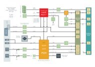
Block Diagram<br />
SP2<br />
ADM<br />
211<br />
SD<br />
J-SP2<br />
CG2-SHANTY • <strong>CompactPCI</strong> GPS Receiver/Clock<br />
GPS<br />
Ant<br />
Differential GPS<br />
(Option)<br />
RTCM SC-104<br />
Serial<br />
Port 2<br />
3V<br />
VBATT<br />
DGPS<br />
RXD<br />
Jupiter<br />
GPS Receiver<br />
ANT<br />
PWR<br />
GPS<br />
RXD/TXD<br />
Serial<br />
Port 1<br />
ACK#/INTR#<br />
IEEE1284<br />
PCI<br />
QUAD UART<br />
& Parallel Port<br />
© EKF<br />
Block Diagram<br />
CG2-SHANTY<br />
PCI 32-bit<br />
- 7 -<br />
EKF Elektronik GmbH • Philipp-Reis-Str. 4 • 59065 HAMM • Germany<br />
Tel. +49 (0)2381/6890-0 • Fax. +49 (0)2381/6890-90 • E-Mail info@ekf.de • Internet www.ekf.com<br />
10kHz<br />
1Hz<br />
GPS NMEA<br />
&<br />
SIRF Binary<br />
J-ANT<br />
J-UTC1<br />
SP3 SP4<br />
Serial<br />
Port 3<br />
Optional<br />
CU-Module<br />
Connectors<br />
J-UTC3<br />
+5V<br />
+3.3V<br />
Serial<br />
Port 4<br />
INTP<br />
<strong>CompactPCI</strong> <strong>J1</strong>
Top View Component Assembly<br />
SMB ANT<br />
LED1<br />
SP2<br />
CG2-SHANTY • <strong>CompactPCI</strong> GPS Receiver/Clock<br />
J-SP2<br />
GPS Receiver<br />
Module<br />
1<br />
1<br />
SP3<br />
SP4<br />
© EKF<br />
ekf.com<br />
© EKF CG2-SHANTY<br />
<strong>CompactPCI</strong><br />
<strong>J1</strong><br />
- 8 -<br />
EKF Elektronik GmbH • Philipp-Reis-Str. 4 • 59065 HAMM • Germany<br />
Tel. +49 (0)2381/6890-0 • Fax. +49 (0)2381/6890-90 • E-Mail info@ekf.de • Internet www.ekf.com<br />
J-BAT<br />
+5V<br />
+3.3V<br />
J-ANT<br />
J-M1<br />
J-UTC3<br />
J-UTC2<br />
J-UTC1<br />
1<br />
2<br />
3 1s<br />
BATT<br />
10kHz
Front Panel<br />
CG2-SHANTY • <strong>CompactPCI</strong> GPS Receiver/Clock<br />
CG2-<br />
SHANTY<br />
GPS ANT<br />
S<br />
P<br />
2<br />
U<br />
T<br />
C<br />
DGPS<br />
R<br />
X<br />
GPS<br />
- 9 -<br />
EKF Elektronik GmbH • Philipp-Reis-Str. 4 • 59065 HAMM • Germany<br />
Tel. +49 (0)2381/6890-0 • Fax. +49 (0)2381/6890-90 • E-Mail info@ekf.de • Internet www.ekf.com<br />
T<br />
X<br />
R<br />
X<br />
D<br />
G<br />
P<br />
S
Front Panel Elements<br />
CG2-SHANTY • <strong>CompactPCI</strong> GPS Receiver/Clock<br />
ANT RF input 1575,42MHz (L1 band), GPS antenna active or passive,<br />
input signal level at -130dBW ... -163dBW, SMB jack, power supply<br />
voltages selectable 0V, +5V, +3.3V (jumper JANT), PolySwitch<br />
resettable fuse 0.5A<br />
SP2 RS-232E D-SUB 9 male connector, can be used either as universal<br />
serial COM-port (standard bitrates up to max. 115,2 kBaud), or as<br />
DGPS input (according to RTCM SC-104 protocol, 9600bps, 8bit, 1<br />
startbit, 1 stopbit, no parity)<br />
LED Array UTC pulse 1s period<br />
RXD/TXD GPS receiver module<br />
RXD serial port SP2<br />
Strapping Headers<br />
JANT Antenna passive, antenna active +5V, antenna active +3.3V<br />
JBAT Lithium battery for data retention of GPS module’s RTC and SRAM<br />
JUTC1<br />
JUTC3<br />
JMP_COM<br />
Connectors & Sockets<br />
TTL time mark pulse 1Hz or 10kHz connected to PCI QUAD UART<br />
(Optional)<br />
TTL time mark pulse 1Hz or 10kHz for synchronisation connected to<br />
INTP (<strong>J1</strong> D4 ) (Optional)<br />
Transceiver for SP2 Enabled/Disabled (Optional)<br />
JUTC2 TTL time mark pulse 1Hz and 10kHz, synchronized to the UTC<br />
Universal Time (Coordinated) (Optional)<br />
- 10 -<br />
EKF Elektronik GmbH • Philipp-Reis-Str. 4 • 59065 HAMM • Germany<br />
Tel. +49 (0)2381/6890-0 • Fax. +49 (0)2381/6890-90 • E-Mail info@ekf.de • Internet www.ekf.com
Installation<br />
Before You Begin<br />
Warnings<br />
CG2-SHANTY • <strong>CompactPCI</strong> GPS Receiver/Clock<br />
The procedures in this chapter assume familiarity with the general terminology associated with<br />
industrial electronics and with safety practices and regulatory compliance required for using and<br />
modifying electronic equipment. Disconnect the system from its power<br />
source and from any telecommunication links, networks or modems before<br />
performing any of the procedures described in this chapter. Failure to<br />
disconnect power, or telecommunication links before you open the system or<br />
perform any procedures can result in personal injury or equipment damage.<br />
Some parts of the system can continue to operate even though the power switch is in its off<br />
state.<br />
Caution<br />
Electrostatic discharge (ESD) can damage components. Perform the procedures described in this<br />
chapter only at an ESD workstation. If such a station is not available, you can<br />
provide some ESD protection by wearing an antistatic wrist strap and attaching it<br />
to a metal part of the system chassis or board front panel. Store the board only<br />
in its original ESD protected packaging. Retain the original packaging (antistatic<br />
bag and antistatic box) in case of returning the board to EKF for rapair.<br />
- 11 -<br />
EKF Elektronik GmbH • Philipp-Reis-Str. 4 • 59065 HAMM • Germany<br />
Tel. +49 (0)2381/6890-0 • Fax. +49 (0)2381/6890-90 • E-Mail info@ekf.de • Internet www.ekf.com
Installing the Board<br />
Warning<br />
CG2-SHANTY • <strong>CompactPCI</strong> GPS Receiver/Clock<br />
This procedure should be done only by qualified technical personnel. Disconnect the system<br />
from its power source before doing the procedures described here. Failure to disconnect power,<br />
or telecommunication links before you open the system or perform any procedures can result in<br />
personal injury or equipment damage.<br />
Typically you will perform the following steps:<br />
C Switch off the system, remove the AC power cord<br />
C Attach your antistatic wrist strap to a metallic part of the system<br />
C Remove the board packaging, be sure to touch the board only at the front panel<br />
C Configure any jumpers on the board according to your application (see next page<br />
‘Jumper Configuration’)<br />
C Identify the related <strong>CompactPCI</strong> slot (peripheral slot for I/O boards)<br />
C Insert card carefully (be sure not to damage components mounted on the bottom side of<br />
the board by scratching neighboured front panels)<br />
C A card with on board connectors requires attachment of associated cabling now<br />
C Lock the ejector lever, fix screws at the front panel (top/bottom)<br />
C Retain original packaging in case of return<br />
- 12 -<br />
EKF Elektronik GmbH • Philipp-Reis-Str. 4 • 59065 HAMM • Germany<br />
Tel. +49 (0)2381/6890-0 • Fax. +49 (0)2381/6890-90 • E-Mail info@ekf.de • Internet www.ekf.com
Jumper Configuration & Factory Defaults<br />
removed<br />
JBAT<br />
CG2-SHANTY • <strong>CompactPCI</strong> GPS Receiver/Clock<br />
Before inserting the CG2-SHANTY into your CPCI enclosure, please control the settings of some<br />
jumper fields on the board. Typically, there are two jumpers that need adjustment.<br />
C Set the jumper JBAT. This enables the Lithium cell, which provides for saving satellite<br />
tracking information in a buffered SRAM, and supplies the RTC, which is operating as<br />
clock source while the system is powered down or there is no receiver signal available on<br />
the antenna input.<br />
C Check the jumper JANT according to the antenna in use. If your antenna is equipped<br />
with a cable more then 2m length, probably it has a built-in amplifier (active antenna).<br />
If you cannot determine the type of antenna, try the passive mode first (JANT open).<br />
Observe the front panel LED UTC, which sends a periodic signal when the receiver gets<br />
valid GPS data (there may be some delay time). If this procedure is not successful, set the<br />
JANT jumper to the +5V active antenna mode. Note: GPS antennas need free sky above<br />
them (mounting outside the building required).<br />
battery not connected<br />
set data retention mode<br />
removed<br />
set 1-2<br />
set 2-3<br />
JANT<br />
1 2 3<br />
1 2 3<br />
passive Antenna<br />
active Antenna +5V<br />
active Antenna +3.3V<br />
1 2 3<br />
WARNING: unmatched JANT settings may destroy antenna<br />
check setting anytime before connecting GPS antenna<br />
JBAT provides for non-volatile GPS RTC &<br />
SRAM data (Lithium cell)<br />
jumper removed - saves cell lifetime while<br />
board storage (delivery status)<br />
jumper set - data retention mode<br />
factory default is off - check this setting if<br />
TTFF is slow<br />
you have to set this jumper on a new board<br />
- EKF opens this jumper for storing and<br />
shipping<br />
Check your antenna type in use! If in doubt,<br />
remove jumper (passive antenna).<br />
If your active antenna needs a +5V power<br />
supply set 1-2<br />
If your active antenna needs a +3.3V power<br />
supply set 2-3<br />
- 13 -<br />
EKF Elektronik GmbH • Philipp-Reis-Str. 4 • 59065 HAMM • Germany<br />
Tel. +49 (0)2381/6890-0 • Fax. +49 (0)2381/6890-90 • E-Mail info@ekf.de • Internet www.ekf.com
CG2-SHANTY • <strong>CompactPCI</strong> GPS Receiver/Clock<br />
C The CG2-SHANTY can be used to synchronize external events with the UTC (Universal<br />
Time Coordinated). Two single row 3-pin headers (JUTC1 & JUTC3) are provided optional<br />
to route the time signal to the UART controller or directly to the INTP pin on the<br />
<strong>CompactPCI</strong> backplane (<strong>J1</strong> D4).<br />
removed<br />
set 1-2<br />
set 2-3<br />
removed<br />
set 1-2<br />
set 2-3<br />
removed<br />
JUTC1<br />
1 2 3<br />
1 2 3<br />
1 2 3<br />
(optional)<br />
JUTC3<br />
1 2 3<br />
1 2 3<br />
1 2 3<br />
(optional)<br />
JMP_COM<br />
not connected<br />
10kHz to UART<br />
1Hz to UART<br />
not connected<br />
10kHz to INTP<br />
1Hz to INTP<br />
C Optional, one single row 2-pin header (JMP_COM) is provided to enable/disable the<br />
onboard RS232 transceiver.<br />
(optional)<br />
Transceiver disabled<br />
set Transceiver enabled<br />
- 14 -<br />
EKF Elektronik GmbH • Philipp-Reis-Str. 4 • 59065 HAMM • Germany<br />
Tel. +49 (0)2381/6890-0 • Fax. +49 (0)2381/6890-90 • E-Mail info@ekf.de • Internet www.ekf.com
Removing the Board<br />
Warning<br />
CG2-SHANTY • <strong>CompactPCI</strong> GPS Receiver/Clock<br />
This procedure should be done only by qualified technical personnel. Disconnect the system<br />
from its power source before doing the procedures described here. Failure to disconnect power,<br />
or telecommunication links before you open the system or perform any procedures can result in<br />
personal injury or equipment damage.<br />
Typically you will perform the following steps:<br />
C Switch off the system, remove the AC power cord<br />
C Attach your antistatic wrist strap to a metallic part of the system<br />
C Identify the board, be sure to touch the board only at the front panel<br />
C unfasten both front panel screws (top/bottom), unlock the ejector lever<br />
C Remove any onboard cabling assembly<br />
C Activate the ejector lever<br />
C Remove the card carefully (be sure not to damage components mounted on the bottom<br />
side of the board by scratching neighboured front panels)<br />
C Store board in the original packaging, do not touch any components, hold the board at<br />
the front panel only<br />
Warning<br />
Do not expose the card to fire. Battery cells and other components could<br />
explode and cause personal injury.<br />
- 15 -<br />
EKF Elektronik GmbH • Philipp-Reis-Str. 4 • 59065 HAMM • Germany<br />
Tel. +49 (0)2381/6890-0 • Fax. +49 (0)2381/6890-90 • E-Mail info@ekf.de • Internet www.ekf.com
EMC Recommendations<br />
CG2-SHANTY • <strong>CompactPCI</strong> GPS Receiver/Clock<br />
In order to comply with the CE regulations for EMC, it is mandatory to observe the following<br />
rules:<br />
C The chassis or rack including other boards in use must comply entirely with CE<br />
C Close all board slots not in use with a blind front panel<br />
C Front panels must be fastened by built-in screws<br />
C Cover any unused front panel mounted connector with a shielding cap<br />
C External communications cable assemblies must be shielded (shield connected only at<br />
one end of the cable)<br />
C Use ferrite beads for cabling wherever appropriate<br />
C Some connectors may require additional isolating parts<br />
Blind CPCI Front<br />
Panels<br />
Reccomended Accessories<br />
Ferrit Bead Filters ARP Datacom,<br />
63115 Dietzenbach<br />
Isolating Elements ARP Datacom,<br />
63115 Dietzenbach<br />
Metal Shielding<br />
Caps<br />
EKF Elektronik Widths currently available<br />
(1HP=5.08mm):<br />
with handle 4HP/8HP<br />
without handle<br />
2HP/4HP/8HP/10HP/12HP<br />
Conec-Polytronic,<br />
59557 Lippstadt<br />
Ordering No.<br />
102 820 (cable diameter 6.5mm)<br />
102 821 (cable diameter 10.0mm)<br />
102 822 (cable diameter 13.0mm)<br />
Ordering No. 182 068<br />
(Cheapernet T-connector)<br />
Ordering No.<br />
CDFA 09 165 X 13129 X (DB9)<br />
CDSFA 15 165 X 12979 X (DB15)<br />
CDSFA 25 165 X 12989 X (DB25)<br />
- 16 -<br />
EKF Elektronik GmbH • Philipp-Reis-Str. 4 • 59065 HAMM • Germany<br />
Tel. +49 (0)2381/6890-0 • Fax. +49 (0)2381/6890-90 • E-Mail info@ekf.de • Internet www.ekf.com
Replacement of the Battery<br />
CG2-SHANTY • <strong>CompactPCI</strong> GPS Receiver/Clock<br />
When your system is turned off, a battery maintains the current time-of-day clock and the values<br />
in the GPS receiver modules CMOS RAM current. The battery allows for nominal 4750hrs data<br />
retention. For replacement, the old battery must be removed from its socket. Change it against<br />
the same type only (Panasonic CR2032 3V). Observe the cell polarization - the ‘+’ mark appears<br />
on top.<br />
Be very careful when removing the battery from its socket. Do not damage any components or<br />
copper traces situated under the battery holder.<br />
Warning<br />
Danger of explosion if the battery is incorrectly replaced. Replace only with the<br />
same or equivalent type. Do not expose a battery to fire.<br />
- 17 -<br />
EKF Elektronik GmbH • Philipp-Reis-Str. 4 • 59065 HAMM • Germany<br />
Tel. +49 (0)2381/6890-0 • Fax. +49 (0)2381/6890-90 • E-Mail info@ekf.de • Internet www.ekf.com
Technical Reference<br />
GPS Receiver Module<br />
General Features<br />
CG2-SHANTY • <strong>CompactPCI</strong> GPS Receiver/Clock<br />
The CG2-SHANTY is equipped with the Navman Jupiter GPS receiver module, a 12 parallel<br />
channel receiver engine. Each of these receivers continuously tracks all satellites in view and<br />
provides accurate satellite positioning data. The Jupiter module size is about 28 square<br />
centimeters and satisfies harsh industrial requirements. The Jupiter module decodes and<br />
processes signals from all visible GPS satellites. These satellites, in various orbits around the<br />
Earth, broadcast radio frequency (RF) ranging codes and navigation data messages. The Jupiter<br />
receiver uses all available signals to produce a highly accurate and robust navigation solution.<br />
The 12-channel architecture provides rapid Time-To-First-Fix (TTFF) under all startup conditions.<br />
While the best TTFF performance is achieved when time of day and current position estimates<br />
are provided to the receiver, the flexible SiRF signal acquisition system takes advantage of all<br />
available information to provide a rapid TTFF. Acquisition is guaranteed under all initialization<br />
conditions as long as visible satellites are not obscured. To minimize TTFF following a power<br />
down, the Jupiter receiver is sourced by a Lithium Cell on the CG2-SHANTY board to maintain<br />
power to the Static Random-Access Memory (SRAM) and Real-Time Clock (RTC) for periods<br />
following the loss of prime power. The use of the battery voltage assures the shortest possible<br />
TTFF following a short power down. The Jupiter receiver supports two dimensional (2-D)<br />
operation when less than four satellites are available or when required by operating conditions.<br />
Altitude information required for 2-D operation is determined by the receiver.<br />
The Jupiter module contains two independent serial ports, one of which is configured for<br />
primary input and output data flow using the National Marine Electronics Association (NMEA-<br />
0183) format. The second port is used to receive Differential GPS (DGPS) corrections in the Radio<br />
Technical Commission For Maritime Services (RTCM SC-104) format. The Jupiter receiver<br />
supports DGPS operations for dramatically improved accuracies over standard GPS (while<br />
Selective Availability is activated by US government). The primary I/O port of the Jupiter (NMEA)<br />
is connected to the first port of the UART controller, while the secondary port (RTCM) ist<br />
connected to both the front panel connector SP2 and the second port of the UART controller of<br />
the CG2-SHANTY (see block diagram CG2-SHANTY).<br />
For applications that require timing synchronization to GPS accuracies, the Jupiter receiver<br />
provides an output timing pulse that is synchronized to one second Universal Time Coordinated<br />
(UTC) boundaries. This timing pulse is available by an two single row headers JUTC1 and JUTC3<br />
on the CG2-SHANTY board. This timing signal could generate a timing interrupt on the UART<br />
controller therefore JUTC1 should be set. Its also possible to use this timing signal to generate<br />
a timing interrupt directly on the INTP of the <strong>CompactPCI</strong> bus (<strong>J1</strong> d4). The <strong>CompactPCI</strong> CPU<br />
boards CC9-SAMBA and CD2-BEBOP are already capable of handling this interrupt. This timing<br />
pulse is also used to drive an indicator LED visible from the CG2-SHANTY boards front panel.<br />
- 18 -<br />
EKF Elektronik GmbH • Philipp-Reis-Str. 4 • 59065 HAMM • Germany<br />
Tel. +49 (0)2381/6890-0 • Fax. +49 (0)2381/6890-90 • E-Mail info@ekf.de • Internet www.ekf.com
Serial Ports & Protocols<br />
CG2-SHANTY • <strong>CompactPCI</strong> GPS Receiver/Clock<br />
The Jupiter module communicates with the host across its primary serial port. The bit rate is<br />
fixed to 4800bps, no parity, 8 data bits, 1 stop bit. Commands are passed to the module, which<br />
responds accordingly with results and status information. Due to the low data transfer rates,<br />
there is no hardwired handshake available.<br />
There are two choices for protocol selection. By default, the NMEA standard is selected on the<br />
Jupiter Module. This is an ASCII based protocol, widely accepted as a common base to all GPS<br />
application programs. As an alternate, the Jupiter module can be configured to communicate<br />
by a proprietary, binary protocol (SiRF binary messages). On writing own firmware, the binary<br />
protocol could be a more efficient solution. The binary protocol also allows for defining higher<br />
bit rates on both serial interfaces. Please contact EKF when you need the binary protocol feature.<br />
The secondary (auxiliary) serial port of the Jupiter module is configured as a half duplex input at<br />
9600bps, no parity, 8 data bits, one stop bit. This interface is configured to receive RTCM DGPS<br />
correction data messages. Usage of this port is optional.<br />
There are four indicator LEDs mounted in the front panel to signal both RXD and TXD of the<br />
primary serial interface, and RXD only of the auxiliary serial interface.<br />
Auxiliary Power<br />
The CG2-SHANTY is equipped with a Lithium cell battery. Close the jumper JBAT to provide this<br />
auxiliary power to the Jupiter receiver module (you have to set this jumper for any new board,<br />
because the factory default is off for saving cell lifetime while storing). Data retention for the<br />
GPS receivers SRAM and RTC is nominal 4750hrs. Loss of SRAM or RTC data results in slower<br />
response time (TTFF) after powering up the CG2-SHANTY, but the GPS receiver remains fully<br />
operable. For replacement of the battery, observe precautions and follow the procedure<br />
described in chapter ‘Replacement of the Battery’.<br />
removed<br />
JBAT<br />
battery not connected<br />
set data retention mode<br />
- 19 -<br />
EKF Elektronik GmbH • Philipp-Reis-Str. 4 • 59065 HAMM • Germany<br />
Tel. +49 (0)2381/6890-0 • Fax. +49 (0)2381/6890-90 • E-Mail info@ekf.de • Internet www.ekf.com
Antenna Connector<br />
CG2-SHANTY • <strong>CompactPCI</strong> GPS Receiver/Clock<br />
The Jupiter receiver is equipped with a SMB type miniature coaxial female connector as RF signal<br />
input from the antenna. The antenna cable therefore should provide a matching SMB plug.<br />
When ordering an antenna, be sure to have selected the SMB connector version, if the antenna<br />
cable is directly attached (there are several other common connector types on the market, e.g.<br />
SMA, TNC and OSX). If the antenna is equipped with a built-in connector, an additional adapter<br />
cable is required, matching both, the antenna type of connector at the outer end, and a SMB<br />
male connector on the CG2-SHANTY side. The SMB connector should be a straight type, not<br />
right angle style. A right angle connector might have a profile too low to allow full insertion into<br />
the matching jack on the CG2-SHANTY, which is mounted behind the front panel, due to EMC<br />
requirements.<br />
For best results, use an active GPS antenna with built-in amplifier, especially when the cable<br />
length exceeds 2m. Typical gain is 10...50db; a longer cable needs higher gain to compensate<br />
its loss. Active antennas are powered by +3.3V or +5V across the coaxial cable, selected by the<br />
jumper field JANT. Do not obscure the antenna (mounting outside of the building required).<br />
removed<br />
set 1-2<br />
set 2-3<br />
JANT<br />
1 2 3<br />
1 2 3<br />
passive Antenna<br />
active Antenna +5V<br />
active Antenna +3.3V<br />
1 2 3<br />
WARNING: unmatched JANT settings may destroy antenna<br />
check setting anytime before connecting GPS antenna<br />
Heavy Duty Airborne GPS Antenna<br />
- 20 -<br />
EKF Elektronik GmbH • Philipp-Reis-Str. 4 • 59065 HAMM • Germany<br />
Tel. +49 (0)2381/6890-0 • Fax. +49 (0)2381/6890-90 • E-Mail info@ekf.de • Internet www.ekf.com
Jupiter Module Socket<br />
CG2-SHANTY • <strong>CompactPCI</strong> GPS Receiver/Clock<br />
The Jupiter receiver module fits into a dual row, 20-position, 2.0mm metric socket and is<br />
mechanically fixed by 4 screws .<br />
+3.3V 1<br />
+3.3V 1<br />
GYRO 5<br />
GPIO3 4<br />
Socket1<br />
1 2 +3.3V/+5V Antenna 2<br />
3 4 VBATT<br />
5 6 RESET#<br />
7 8 GPIO2 4<br />
GND 9 10 SPEED 5<br />
Serial Data In 1 11 12 Serial Data Out 1<br />
NC 13 14 GND<br />
GND 15 16 Serial Data In 2 3<br />
GND 17 18 GND<br />
UTC 10kHz 19 20 UTC TMARK<br />
1 Jupiter receiver power, fused by PolySwitch 0.5A<br />
2 Antenna power, from JANT, selectable NC/+3.3V/+5V, fused by PolySwitch 0.5A<br />
3 RTCM DGPS optional input, can be fully deactivated by removing R12 and placing R11<br />
4 GPIO2/3 inputs are used to setup some Jupiter options, see table below<br />
5 Connector pin function only in combination with Jupiter 21D (optional)<br />
GPIO2 Resistor Stuffed Jupiter Option<br />
0 R10 stuffed NMEA 4800bps ASCII protocol, no parity, 1 start bit, 8 data<br />
bits, 1 stop bit, default<br />
GPIO3 Resistor Stuffed Jupiter Option<br />
0 R8 stuffed<br />
R7 removed<br />
1 R7 stuffed<br />
R8 removed<br />
Jupiter receiver gets its initializing parameters from its ROM<br />
Jupiter tries to read initializing parameters from its SRAM first (if<br />
valid), else from its EEPROM (if valid), else falls back to its ROM<br />
stored parameters, default<br />
- 21 -<br />
EKF Elektronik GmbH • Philipp-Reis-Str. 4 • 59065 HAMM • Germany<br />
Tel. +49 (0)2381/6890-0 • Fax. +49 (0)2381/6890-90 • E-Mail info@ekf.de • Internet www.ekf.com
Jumper JUTC, Time Mark<br />
CG2-SHANTY • <strong>CompactPCI</strong> GPS Receiver/Clock<br />
The CG2-SHANTY can be used to synchronize external events with the UTC (Universal Time<br />
Coordinated). The board generates two output signals, named utctmark and utc10kHz, which<br />
can be used for various purposes. Both signals are wired to the (optional) 3-pin header<br />
connector JUTC.<br />
JUTC2<br />
10kHz 1Hz TMARK<br />
1 GND 3<br />
(Optional)<br />
This connector is located near the Lithium cell. If the board is not equipped with this (optional)<br />
connector, the position can easily filled by the customer with a three pin 0.1" (2.54mm) pitch<br />
header.<br />
The Time Mark output utctmark provides a one pulse-per-second (1pps) signal to the user<br />
specific application. When the receiver provides a valid navigation solution, the rising edge of<br />
each utctmark pulse is synchronized with the UTC one second epochs to within ±300ns. This<br />
signal is a positive logic, buffered CMOS level output pulse that transitions from a logic 'low'<br />
condition to a logic 'high' at a 1 Hz rate. The pulse duration is typically 25.6ms. The 10kHz UTC<br />
Synchronized Clock signal utc10kHz is a symmetric, buffered CMOS level output, synchronized<br />
to the utctmark pulse.<br />
- 22 -<br />
EKF Elektronik GmbH • Philipp-Reis-Str. 4 • 59065 HAMM • Germany<br />
Tel. +49 (0)2381/6890-0 • Fax. +49 (0)2381/6890-90 • E-Mail info@ekf.de • Internet www.ekf.com
Additional Documentation<br />
CG2-SHANTY • <strong>CompactPCI</strong> GPS Receiver/Clock<br />
In addition to this manual, EKF provides detailed on-line information regarding the Jupiter<br />
receiver module (PDF documents). Also use the Navman homepage for most recent information:<br />
http://www.navman.com<br />
Document Title URL http://<br />
Jupiter 21 GPS Receiver<br />
Data Sheet<br />
www.ekf.com/c/cgps/cg2/inf/jupiter21_datasheet.pdf<br />
NMEA Reference Manual www.ekf.com/c/cgps/cg2/inf/nmea_reference_manual.pdf<br />
SiRF Binary Protocol Reference<br />
Manual<br />
pointers to some other<br />
documentation<br />
www.ekf.com/c/cgps/cg2/inf/binary_reference_manual.pdf<br />
www.ekf.com/c/cgps/cg2/cg2_e.html<br />
The NMEA and RTCM protocol specifications can be obtained from<br />
http://www.nmea.org/<br />
http://www.rtcm.org/<br />
- 23 -<br />
EKF Elektronik GmbH • Philipp-Reis-Str. 4 • 59065 HAMM • Germany<br />
Tel. +49 (0)2381/6890-0 • Fax. +49 (0)2381/6890-90 • E-Mail info@ekf.de • Internet www.ekf.com
Serial Interfaces<br />
General Information<br />
CG2-SHANTY • <strong>CompactPCI</strong> GPS Receiver/Clock<br />
The CG2-SHANTY is provided with two serial interfaces. The first one is directly connected to the<br />
NMEA (primary port) of the Jupiter GPS receiver. Commands and data are passed bidirectionally<br />
across this interface, either ASCII coded using the NMEA protocol (by default), or using the SiRF<br />
binary (proprietary) protocol. This port normally operates at 4800bps, no parity, 8 data bits, one<br />
stop bit, and is not available for external usage.<br />
The second serial port is available by the front panel connector SP2, configured as RS-232E<br />
interface. It is intended mainly to receive RTCM DGPS data to sharpen GPS positioning<br />
information. A tap is established leading to the auxiliary serial interface on the Jupiter module.<br />
This port normally operates at 9600bps, no parity, 8 data bits, one stop bit, when used as DGPS<br />
input.<br />
If there is no need for an external DGPS receiver (due to deactivated GPS SA, or when using GPS<br />
timing information only), the second serial port SP2 can be used as general purpose serial<br />
interface, like any PC style COM port. The connector SP2 is described in detail later on in this<br />
document.<br />
There are indicator LEDs mounted in the front panel to signal both RXD and TXD of the first<br />
(internal) serial interface, and RXD only of the second serial interface.<br />
U<br />
T<br />
C<br />
DGPS<br />
GPS<br />
R<br />
X<br />
T<br />
X<br />
R<br />
X<br />
- 24 -<br />
EKF Elektronik GmbH • Philipp-Reis-Str. 4 • 59065 HAMM • Germany<br />
Tel. +49 (0)2381/6890-0 • Fax. +49 (0)2381/6890-90 • E-Mail info@ekf.de • Internet www.ekf.com<br />
CG2-<br />
SHANTY<br />
GPS ANT<br />
DGPS<br />
GPS<br />
U<br />
T<br />
C<br />
S<br />
P<br />
2<br />
R<br />
X<br />
T R<br />
X X<br />
D<br />
G<br />
P<br />
S
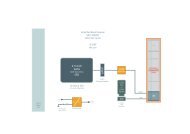
Connector SP2<br />
CG2-SHANTY • <strong>CompactPCI</strong> GPS Receiver/Clock<br />
The illustration below shows the pin assignment of the connector SP2 (front view to the<br />
connector). Signal directions are seen from the view of the CG2-SHANTY, e.g. RXD (SP2, pin 2)<br />
is an input to the CG2-SHANTY.<br />
DSR<br />
RTS<br />
CTS<br />
RI<br />
Male D-Sub 9 Connector (PC compatible)<br />
DSR 6<br />
RTS 7<br />
CTS 8<br />
RI 9<br />
6<br />
9<br />
SP2 (RS-232E)<br />
1 DCD<br />
2 RXD<br />
3 TXD<br />
4 DTR<br />
5 GND<br />
The signal RXD (typically data from external DGPS receiver) can be observed from an indicator<br />
LED mounted in the front panel of the CG2-SHANTY.<br />
- 25 -<br />
EKF Elektronik GmbH • Philipp-Reis-Str. 4 • 59065 HAMM • Germany<br />
Tel. +49 (0)2381/6890-0 • Fax. +49 (0)2381/6890-90 • E-Mail info@ekf.de • Internet www.ekf.com<br />
1<br />
5<br />
CG2-SHANTY<br />
SP2 (RS-232E)<br />
male D-SUB<br />
DCD<br />
RxD<br />
TxD<br />
DTR<br />
GND
CG2-SHANTY • <strong>CompactPCI</strong> GPS Receiver/Clock<br />
The following figure shows the wiring scheme of a standard RS-232 link cable usually in use to<br />
connect a port of the CG2-SHANTY with another RS-232 port, e.g. a COM port of a PC:<br />
Link Cable RS-232<br />
for interconnection between CG2-SHANTY<br />
serial port (SP2) and PC COM port<br />
1<br />
DCD<br />
RxD<br />
TxD<br />
DTR<br />
6<br />
DSR<br />
RTS<br />
CTS<br />
DCD<br />
RxD<br />
TxD<br />
DTR<br />
GND GND<br />
5<br />
9<br />
connectors: shielded female D-SUB 9<br />
complete cable assembly available<br />
EKF part no. 280.7.201<br />
DSR<br />
RTS<br />
- 26 -<br />
EKF Elektronik GmbH • Philipp-Reis-Str. 4 • 59065 HAMM • Germany<br />
Tel. +49 (0)2381/6890-0 • Fax. +49 (0)2381/6890-90 • E-Mail info@ekf.de • Internet www.ekf.com<br />
1<br />
5<br />
6<br />
9<br />
CTS
CG2-SHANTY • <strong>CompactPCI</strong> GPS Receiver/Clock<br />
To establish a connection between the serial port SP2 and the external DGPS receiver, a three<br />
wire cable should be used as shown in the diagram below:<br />
UB<br />
6<br />
9<br />
Connection Cable RS-232<br />
for interconnection between<br />
CG2 serial port (SP2) and<br />
WZ WFE97 DGPS Receiver<br />
1<br />
5<br />
WZ WFE97<br />
DGPS<br />
RTCM Data<br />
- 27 -<br />
EKF Elektronik GmbH • Philipp-Reis-Str. 4 • 59065 HAMM • Germany<br />
Tel. +49 (0)2381/6890-0 • Fax. +49 (0)2381/6890-90 • E-Mail info@ekf.de • Internet www.ekf.com<br />
DCD<br />
RxD<br />
TxD<br />
DTR<br />
GND GND<br />
connectors shielded D-SUB 9<br />
CG2-SHANTY: female connector<br />
WZ WFE97 DGPS: male connector<br />
cable is included with DGPS receiver<br />
1<br />
5<br />
6<br />
9<br />
CG2-SHANTY<br />
SP2<br />
DSR<br />
RTS<br />
CTS<br />
RI
<strong>CompactPCI</strong> ® Interface<br />
CG2-SHANTY • <strong>CompactPCI</strong> GPS Receiver/Clock<br />
The CG2-SHANTY offers a <strong>CompactPCI</strong> ® interface complying to the <strong>CompactPCI</strong> ® Specification<br />
Revision 2.1. <strong>CompactPCI</strong> ® is an industrial implementation of the familiar Peripheral Component<br />
Interconnect (PCI) bus. It combines the well known electrical features of PCI with the more<br />
robust mechanical 19 inch rack mounting technology. The interface supports 64-bit address and<br />
32-bit data transfers. It is designed for a clock frequency of 33 MHz with a transfer rate of up to<br />
132 Mbyte/s.<br />
PCI Devices<br />
The <strong>CompactPCI</strong> ® interface is realized by the UART Controller (Oxford OXmPCI954). This<br />
controller has four UARTs (Universal Asynchronous Receiver Transmitter. Two ports are<br />
internally used, the other two ports could be used for custom specific solutions. Normally a<br />
BIOS running on a host system detects these PCI devices at boot time.<br />
- 28 -<br />
EKF Elektronik GmbH • Philipp-Reis-Str. 4 • 59065 HAMM • Germany<br />
Tel. +49 (0)2381/6890-0 • Fax. +49 (0)2381/6890-90 • E-Mail info@ekf.de • Internet www.ekf.com
System Connector <strong>J1</strong><br />
CG2-SHANTY • <strong>CompactPCI</strong> GPS Receiver/Clock<br />
The <strong>CompactPCI</strong> ® specification defines the usage of shielded, 2 mm-pitch, 5-row connectors on<br />
<strong>CompactPCI</strong> ® boards according to IEC 917 and IEC 1076-4-101. The 32-bit PCI interface is<br />
implemented via the <strong>J1</strong> connector, while the 64-bit option requires the connector J2. Since the<br />
CG2-SHANTY has a 32-bit <strong>CompactPCI</strong> ® interface, the J2 connector is not necessary and thus<br />
not mounted.<br />
The <strong>J1</strong> connector also defines the supported signaling voltage (V I/O). A coding key in this<br />
connector is used to distinguish boards with V I/O=3.3V (cadmium yellow key), V I/O=5V (brilliant<br />
blue key) or both (no key). The CG2-SHANTY is suitable for V I/O=3.3V and V I/O=5V and therefore<br />
not equipped with any coding key.<br />
- 29 -<br />
EKF Elektronik GmbH • Philipp-Reis-Str. 4 • 59065 HAMM • Germany<br />
Tel. +49 (0)2381/6890-0 • Fax. +49 (0)2381/6890-90 • E-Mail info@ekf.de • Internet www.ekf.com
CG2-SHANTY • <strong>CompactPCI</strong> GPS Receiver/Clock<br />
<strong>CompactPCI</strong> <strong>J1</strong><br />
#<strong>J1</strong> A B C D E<br />
25 +5V REQ64# ENUM# +3.3V +5V<br />
24 AD1 +5V VI/O AD0 ACK64#<br />
23 +3.3V AD4 AD3 +5V AD2<br />
22 AD7 GND +3.3V AD6 AD5<br />
21 +3.3V AD9 AD8 M66EN C/BE0#<br />
20 AD12 GND VI/O AD11 AD10<br />
19 +3.3V AD15 AD14 GND AD13<br />
18 SERR# GND +3.3V PAR C/BE1#<br />
17 +3.3V IPMB SCL IPMB SDA GND PERR#<br />
16 DEVSEL# GND VI/O STOP# LOCK#<br />
15 +3.3V FRAME# IRDY# BD_SEL# TRDY#<br />
14<br />
13 Not Keyed<br />
12<br />
11 AD18 AD17 AD16 GND C/BE2#<br />
10 AD21 GND +3.3V AD20 AD19<br />
9 C/BE3# IDSEL AD23 GND AD22<br />
8 AD26 GND VI/O AD25 AD24<br />
7 AD30 AD29 AD28 GND AD27<br />
6 REQ# GND +3.3V CLK AD31<br />
5 BRSVP1A5 BRSVP1B5 RST# GND GNT#<br />
4 IPMB PWR GND VI/O INTP INTS<br />
3 INTA# INTB# INTC# +5V INTD#<br />
2 TCK +5V TMS TDO 1<br />
1 +5V 2<br />
-12V 2<br />
TRST# +12V 2<br />
Pin positions printed italic/gray: Not connected<br />
1 TDI/TDO internally connected together<br />
2 +5V/+12V/-12V not required<br />
TDI 1<br />
+5V<br />
- 30 -<br />
EKF Elektronik GmbH • Philipp-Reis-Str. 4 • 59065 HAMM • Germany<br />
Tel. +49 (0)2381/6890-0 • Fax. +49 (0)2381/6890-90 • E-Mail info@ekf.de • Internet www.ekf.com
Literature<br />
CG2-SHANTY • <strong>CompactPCI</strong> GPS Receiver/Clock<br />
Theme Document Title Origin<br />
<strong>CompactPCI</strong><br />
Specification<br />
<strong>CompactPCI</strong> Specification, PICMG<br />
2.0 R3.0, Oct. 1, 1999<br />
PCI PCI Hardware and Software<br />
Architecture & Design, Solari/Willse,<br />
4th Edition, Annabooks<br />
Metric Connectors IEC 1076-4-101<br />
Application Literature from ERNI,<br />
AMP, FCI<br />
2.54mm<br />
Shrouded Headers<br />
PICMG (http://www.picmg.org)<br />
Annabooks<br />
(http://www.annabooks.com)<br />
Beuth Verlag, Berlin<br />
ILI Index House, GB SL57EU<br />
Ascot Berkshire<br />
DIN 41651 Beuth Verlag, Berlin<br />
- 31 -<br />
EKF Elektronik GmbH • Philipp-Reis-Str. 4 • 59065 HAMM • Germany<br />
Tel. +49 (0)2381/6890-0 • Fax. +49 (0)2381/6890-90 • E-Mail info@ekf.de • Internet www.ekf.com
EKF Elektronik GmbH<br />
Philipp-Reis-Str. 4<br />
59065 HAMM<br />
Germany<br />
CG2-SHANTY • <strong>CompactPCI</strong> GPS Receiver/Clock<br />
Fax. +49 (0)2381/6890-90<br />
Tel. +49 (0)2381/6890-0<br />
Internet www.ekf.com<br />
E-Mail info@ekf.de