Model YLAA Air-Cooled Scroll Chillers Style A - Johnson Controls
Model YLAA Air-Cooled Scroll Chillers Style A - Johnson Controls
Model YLAA Air-Cooled Scroll Chillers Style A - Johnson Controls

Create successful ePaper yourself
Turn your PDF publications into a flip-book with our unique Google optimized e-Paper software.
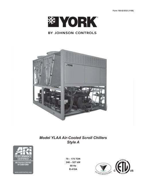
Form 150.62-EG3 (1108)<strong>Model</strong> <strong>YLAA</strong> <strong>Air</strong>-<strong>Cooled</strong> <strong>Scroll</strong> <strong>Chillers</strong><strong>Style</strong> A70 – 175 TON246 – 527 kW60 HzR-410A
Table of contentsForm 150.62-EG3 (1108)........................................................................................................................................................................................ 1Introduction........................................................................................................................................................................................................... 3Specifications........................................................................................................................................................................................................ 4Microcomputer Control Center............................................................................................................................................................................ 5Accessories and Options..................................................................................................................................................................................... 7Design Parameters............................................................................................................................................................................................. 10Water Pressure Drop...........................................................................................................................................................................................11Selection Criteria and Procedures.................................................................................................................................................................... 12Pump Selection Criteria..................................................................................................................................................................................... 14Pump Pressure Drop Curves............................................................................................................................................................................. 16Single Pump Curves........................................................................................................................................................................................... 18Dual Pump Curves.............................................................................................................................................................................................. 19Ratings - 60 Hz.................................................................................................................................................................................................... 20Part Load Ratings - Standard Efficiency.......................................................................................................................................................... 28Part Load Ratings - High Efficiency.................................................................................................................................................................. 29Physical Data - English...................................................................................................................................................................................... 30Dimensions - Four Fan Units............................................................................................................................................................................. 32Dimensions - Five Fan Units.............................................................................................................................................................................. 33Dimensions - Six Fan Units................................................................................................................................................................................ 34Dimensions - Eight Fan Units............................................................................................................................................................................ 35Dimensions - Ten Fan Units............................................................................................................................................................................... 36Isolator Locations............................................................................................................................................................................................... 37Isolator Details.................................................................................................................................................................................................... 40Electrical Notes................................................................................................................................................................................................... 44Electrical Data w/o Pumps................................................................................................................................................................................. 46Wiring Lugs......................................................................................................................................................................................................... 50Electrical Data w/ Pumps................................................................................................................................................................................... 52Wiring Diagram.................................................................................................................................................................................................... 62Elementary Wiring .............................................................................................................................................................................................. 64Condenser Fan Mapping and Sequencing....................................................................................................................................................... 66Compressor Wiring............................................................................................................................................................................................. 67Power Options Connection Diagram................................................................................................................................................................. 68Power Panel......................................................................................................................................................................................................... 69Dual Pump Wiring............................................................................................................................................................................................... 70Wiring................................................................................................................................................................................................................... 71MicroPanel Connections.................................................................................................................................................................................... 72Application Data.................................................................................................................................................................................................. 75Guide Specifications.......................................................................................................................................................................................... 76NOMENCLATUREThe model number denotes the following characteristics of the unit:0070TEYork ChillerA = AmericasFour Digit Unit NumberE410AUnit DesignatorS = Standard EfficiencyH = High EfficiencyY = Standard Efficiency (round tube)Z = High Efficiency (round tube)jOHNSON CONTROLS
IntroductionFORM 150.62-eg3 (1108)TempoNew Pace…New WorldTry keeping up with our Tempo!<strong>Johnson</strong> <strong>Controls</strong>, the leader in equipmentcontrols and HVAC equipment is proud tooffer the YORK air-cooled scroll chiller.This all-in-one package is a true plug andplay system that provides superb efficiencyand performance. The chiller is completely self-contained and is designed for outdoor (roof or groundlevel) installation. An optional hydronic pump kit makes service replacement or new building installationsvery convenient. Each unit includes zero-ozone-depletion refrigerant (R-410A), hermetic scroll compressors,a liquid evaporator, air cooled condenser, and a weather resistant microprocessor control center,all mounted on a formed steel base.Environmental Responsibility …StandardTEMPO makes you the leader in environmental practicesthrough innovation, not added cost. With the combination of R-410A refrigerant and a 30-50% reduction of refrigerant used vs.similar chillers, the TEMPO chiller provides you with the mostecologically friendly equipment. Partnered with it’s low soundproperties (for noise pollution prevention), this chiller is a trueearth-friendly offering.Reduced Total Cost of Ownership...Industry leading energy efficiency, easy maintenance anddurability minimize your cost of ownership. Efficiency; environmentallyresponsibility that pays you back…• Real world energy efficiency is measured in IPLV (part load)performance• Tempo’s industry leading IPLV’s deliver cash to your bottomline• Serviceability…Easier maintenance pays twice: sustainedchiller efficiency and lower cost maintenance contracts• Corrosion resistant condenser coils extend life and improveperformanceMore Building…Less ChillerTEMPO offers a lighter, smaller and quieter chiller minimizingyour installed cost and maximizing usable building space.jOHNSON CONTROLS• More space for you• Smaller chiller footprint saves valuable space• Tempo is the lowest weight chiller available, lighter than ourprevious generation chiller by 20-35%• Hydronic pump kit option can save both space and cost byintegrating the chilled water pumps as a factory mountedchiller option• Standard low sound and affordable sound attenuation optionsallow flexibility in locating chiller and reduce cost forfield constructed sound barriersMany Applications, One Tempo!Performance, sound and hydronic pump kits are all configurableto suit your many needs… Performance can be configured withstandard and high full-load efficiency models (an industry first)• Multiple sound configurations…only spend on what youneed.• Pumps can be factory mounted• Hydronic pump kits can be configured for a wide range of flowand head pressure with single or dual (standby) pump• Standard corrosion resistance for coastal applications• Small weight and footprint allow you maximum choice in locatingthe chiller
Microcomputer Control Center - continued• Anti-recycle timer status for each system• Anti-coincident system start timer condition• Compressor run status• No cooling load condition• Day, date and time• Daily start/stop times• Holiday status• Automatic or manual system lead/lag control• Lead system definition• Compressor starts & operating hours(each compressor)• Status of hot gas valves, evaporator heaterand fan operation• Run permissive status• Number of compressors running• Liquid solenoid valve status• Load & unload timer status• Water pump statusProvisions are included for: pumpdown at shutdown;optional remote chilled water temperature reset and twosteps of demand load limiting from an external buildingautomation system. Unit alarm contacts are standard.The operating program is stored in non-volatile memory(EPROM) to eliminate chiller failure due to AC poweredfailure/battery discharge. Programmed setpoints are retainedin lithium battery-backed RTC memory for 5 yearsminimum.HIGH AMBIENT KITAllows units to operate when the ambient temperatureis above 115°F (46°C). Includes sun shield panels anddischarge pressure transducers.BUILDING AUTOMATION SYSTEM INTERFACEThe factory addition of a Printed Circuit Board to accepta 4-20 milliamp, 0-10VDC input to reset the leaving chillerliquid temperature from a Building Automation System.(Only one of following options can be offered on a unit ata time: BAS, Remote Control Panel or Multi-unit SequenceControl.) (Factory-mounted)- (The standard unit capabilities include remote startstop,remote water temperature reset via a PWM inputsignal or up to two steps of demand (load) limitingdepending on model.)- (The standard control panel can be directly connectedto a <strong>Johnson</strong> <strong>Controls</strong> Building Automated System viathe standard on-board RS232 communication port.)POWER PANELEach panel contains:• Compressor power terminals• Compressor motor starting contactors per l.E.C.• Control power terminals to accept incoming for115-1-60 control power• Fan contactors & overload current protectionThe power wiring is routed through liquid-tight conduit tothe compressors and fans.FANCONTACTORFANFUSEFANCONTACTORSDISCONNECTSWITCHFANCONTACTORSFANFUSEFANCONTACTORXTBF1COMPRESSORCONTACTORSGROUNDLUGCOMPRESSORCONTACTORSCOMPRESSOROVERLOADSFig. 2 – power panel componentsjOHNSON CONTROLS
Accessories and OptionsFORM 150.62-eg3 (1108)POWER OPTIONS:COMPRESSOR POWER CONNECTIONS – Single-pointterminal block connection(s) are provided as standard.The following power connections are available as options.(See electrical data for specific voltage and options availability.)(Factory-mounted)SINGLE-POINT SUPPLY TERMINAL BLOCK – Includesenclosure, terminal-block and interconnectingwiring to the compressors. Separate external protectionmust be supplied, by others, in the incomingcompressor-power wiring. (Do not include this optionif either the Single-Point Non-Fused Disconnect Switchor Single-Point Circuit Breaker options have beenincluded.)SINGLE- POINT NON- FUSED DISCONNECTSWITCH – Unit-mounted disconnect switch(es) withexternal, lockable handle (in compliance with Article440-14 of N.E.C.), can be supplied to isolate the unitpower voltage for servicing. Separate external fusingmust be supplied, by others in the power wiring, whichmust comply with the National Electrical Code and/orlocal codes.SINGLE-POINT NON-FUSED DISCONNECT SWITCHWITH INDIVIDUAL SYSTEM BREAKERS - Includesunit-mounted disconnect switch with external, lockablehandles (in compliance with Article 440-14 of N.E.C.)to isolate unit power voltage for servicing. Factoryinterconnecting wiring is provided from the disconnectswitch to factory supplied system circuit breakers.SINGLE-POINT CIRCUIT BREAKER – A unit mountedcircuit breaker with external, lockable handle (incompliance with N.E.C. Article 440-14), can be suppliedto isolate the power voltage for servicing. (This optionincludes the Single-Point Power connection.)CONTROL TRANSFORMER – Converts unit power voltageto 115-1-60 (0.5 or 1.0 KVA capacity). Factory mountingincludes primary and secondary wiring between thetransformer and the control panel. (Factory-mounted)POWER FACTOR CORRECTION CAPACITORS – Willcorrect unit compressor power factors to a 0.90-0.95.(Factory-mounted)CONTROL OPTIONS:AMBIENT KIT (LOW) – Units will operate to 30°F (-1°C).This accessory includes all necessary components to permitchiller operation to 0°F (-18°C). (This option includesthe Discharge Pressure Transducer / Readout Capabilityoption.) For proper head pressure control in applicationsjOHNSON CONTROLSbelow 30°F (-1°C) where wind gusts may exceed 5 mph,it is recommended that Optional Condenser LouveredEnclosure Panels also be included. (Factory-mounted)LANGUAGE LCD AND KEYPAD DISPLAY – Spanish,French, German, and Italian unit LCD controls and keypaddisplay available. Standard language is English.COMPRESSOR, PIPING, EVAPORATORoptions:Flanges (ANSI/AWWA C-606 couplings Type)– Consists of (2) Flange adapter for grooved end pipe(standard 150 psi [10.5 bar] evaporator). (Not availableon optional DX evaporator 300 PSIG DWP waterside.)(Field-mounted)LOW TEMPERATURE BRINE – Required for brinechilling below 30°F (-1°C) leaving brine temperature.Option includes resized thermal expansion valve. (Factory-mounted)CHICAGO CODE RELIEF VALVES – Unit will be providedwith relief valves to meet Chicago code requirements.(Factory-Mounted)SERVICE ISOLATION VALVE – Service suction (optional)and discharge (ball type, standard) isolation valvesare added to unit per system. This option also includesa system high pressure relief valve in compliance withASHRAE 15. (Factory-Mounted)HOT GAS BY-PASS – Permits continuous, stable operationat capacities below the minimum step of compressorunloading to as low as 5% capacity (dependingon both the unit and operating conditions) by introducingan artificial load on the evaporator. Hot gas by-pass isinstalled on only refrigerant system #1 on two-circuitedunits. (Factory-Mounted)FLOW SWITCH – The flow switch or its equivalent mustbe furnished with each unit.150 psig (10.5 bar) DWP – For standard units. <strong>Johnson</strong><strong>Controls</strong> model F61MG-1C Vapor-proof SPDT, NEMA3R switch (150 psig [10.5 bar] DWP), -20°F to 250°F(-29°C to 121°C), with 1" NPT connection for uprightmounting in horizontal pipe. (Field-mounted)Differential Pressure Switch – Alternative to anabove mentioned flow switch. Pretempco model DPS300A-P40PF-82582-5 (300 psi max. working pressure), SPDT 5amp 125/250VAC switch, Range 3 - 40 psid, deadband0.5 - 0.8 psi, with 1/4” NPTE Pressure Connections.
Accessories and Options - continuedHYDRO-KIT – Factory installed Hydro-Kit suitable for waterglycol systems with up to 35% glycol at leaving temperaturesdown to 20 F. The Hydro-kit option is available in asingle or dual configuration (dual as standby duty only), withtotally enclosed permanently lubricated pump motors.The hydro-kit option comes standard with a balancing valve,flow switch, pressure ports, suction guide, strainer, bleedand drain valves and frost protection.Expansion tanks are optional within the Hydro-Kit option.CONDENSER AND CABINET OPTIONS:Condenser coil protection against corrosive environmentsis available by choosing any of the following options. Foradditional application recommendations, refer to FORM150.12-ES1. (Factory-Mounted)POST-COATED DIPPED CONDENSER COILS – Theunit is built with dipped-cured condenser coils. This is thechoice for corrosive applications (with the exception ofstrong alkalies, oxidizers and wet bromine, chlorine andfluorine in concentrations greater than 100 ppm).ENCLOSURE PANELS (UNIT) – Tamperproof EnclosurePanels prevent unauthorized access to units. EnclosurePanels can provide an aesthetically pleasing alternativeto expensive fencing. Additionally, for proper head pressurecontrol, <strong>Johnson</strong> <strong>Controls</strong> recommends the use ofCondenser Louvered Panels for winter applications wherewind gusts may exceed five miles per hour. The followingtypes of enclosure panels are available:WIRE PANELS (Full Unit) – Consists of weldedwire-mesh guards mounted on the exterior of the unit.Prevents unauthorized access, yet provides free air flow.(Factory-Mounted)WIRE/LOUVERED PANELS – Consists of welded wiremeshpanels on the bottom part of unit and louveredpanels on the condenser section of the unit. (Factorymounted).LOUVERED PANELS (Condenser Coil Only)– Louvered panels are mounted on the sides and ends ofthe condenser coils for protection. (Factory-Mounted)LOUVERED PANELS (Full Unit) – Louvered panelssurround the front, back, and sides of the unit. Theyprevent unauthorized access and visually screen unitcomponents. Unrestricted air flow is permitted throughgenerously sized louvered openings. This option is applicablefor any outdoor design ambient temperature upto 115°F (46°). (Factory-Mounted)COIL END HAIL GUARD – Louvered panel attached toexposed coil end. (Factory-Mounted)sound attenuation – One or both of the followingsound attenuation options are recommended for residentialor other similar sound sensitive locations:COMPRESSOR ACOUSTIC SOUND BLANKET – Eachcompressor is individually enclosed by an acoustic soundblanket. The sound blankets are made with one layer ofacoustical absorbent textile fiber of 5/8" (15mm) thickness;one layer of anti-vibrating heavy material thickness of 1/8"(3mm). Both are closed by two sheets of welded PVC,reinforced for temperature and UV resistance. (Factory-Mounted)ULTRA Quiet FANS – Lower RPM, 8-pole fan motorsare used with steeper-pitch fans. (Factory-Mounted)TWO SPEED FANS – Lower RPM, 8-pole fan motors areused with steeper-pitch fans. (Factory-Mounted)VIBRATION ISOLATORS – Level adjusting, spring type 1"(25.4mm) or seismic deflection or neoprene pad isolatorsfor mounting under unit base rails. (Field-mounted)jOHNSON CONTROLS
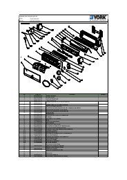
FORM 150.62-eg3 (1108)FAN DECKPOWERPANELCONTROLPANELCOMPRESSORSMICROCHANNELCOILSLIQUIDTIGHTCONDUITFORMEDBASERAILFILTERDRIERSTXVVALVESSIGHTGLASSEVAPORATORfig.3 – general unit componentsjOHNSON CONTROLS
Water Pressure DropFORM 150.62-eg3 (1108)<strong>YLAA</strong> Evaporator Pressure Drop (IP Units)100.0DBFPressure Drop (ft H2O)10.0ACEG1.010 100 1000Water Flow Rate (GPM)EVAPORATORABCDEFG<strong>YLAA</strong> MODELS70SE80SE91HE, 100SE,101HE, 115SE, 125HE120SE, 141HE, 155SE90SE135SE, 150SE, 156HE, 170HE175HEjOHNSON CONTROLS11
Selection Criteria and ProceduresGUIDE TO SELECTIONCapacity ratings for YORK <strong>YLAA</strong> Packaged <strong>Air</strong>-<strong>Cooled</strong>Liquid <strong>Chillers</strong>, shown on pages 18 through 23 cover themajority of design applications for these units. For unusualapplications or uses beyond the scope of this catalog,please consult your nearest <strong>Johnson</strong> <strong>Controls</strong> Office orrepresentative.SELECTION RULES1. Ratings – Ratings may be interpolated, but must notbe extrapolated. The Ratings given on pages 18 through23 and the DESIGN PARAMETERS given on page 10indicate the limits of application for these chillers.2. Evaporator Water – Ratings are based upon 2.4 GPMper ton which is equal to a 10°F chilled water range anda 0.0001 fouling factor for the evaporator at sea level.Tables on pages 18 through 23 give capacity, compressorkW required, evaporator GPM and unit EER.3. Condenser – Ratings are given in terms of air on condenserin degrees Fahrenheit.4. Performance Data Correction Factors – Ratings arebased on 0.0001 evaporator fouling factor, 10°F chilledwater range and at sea level. For operation at differentconditions, apply the appropriate correction factor fromthe following table.FOULING FACTORALTITUDESEA LEVEL2000 FT.4000 FT.6000 FT.TEMPSPLITTONS0.0001 0.00025COMPRkWTONSCOMPRkW8 0.994 0.999 0.991 0.99810 1.000 1.000 0.993 0.99912 1.005 1.001 0.999 0.99914 1.008 1.002 1.005 1.0008 0.990 1.010 0.984 1.00910 0.995 1.010 0.990 1.00912 0.999 1.011 0.995 1.01014 1.004 1.015 0.998 1.0118 0.983 1.021 0.977 1.02010 0.989 1.024 0.983 1.02112 0.994 1.025 0.988 1.02414 0.997 1.026 0.993 1.0258 0.978 1.035 0.973 1.03410 0.982 1.037 0.978 1.03512 0.987 1.037 0.980 1.03614 0.992 1.038 0.986 1.0376. Ethylene Glycol Correction Factors – The followingfactors are to be applied to the standard ratings for unitscooling ethylene glycol.ETHYLENE GLYCOL%WEIGHTTONSGPM°F/ PRESSCOMPRkW TON DROP10 0.985 0.997 24.1 1.034 2620 0.981 0.996 24.9 1.062 1630 0.974 0.995 26.1 1.096 540 0.966 0.991 27.5 1.134 -10FREEZEPT50 0.957 0.989 29.1 1.172 -327. Propylene Glycol Correction Factors – The followingfactors are to be applied to the standard ratings for unitscooling propylene glycol.PROPYLENE GLYCOL%WEIGHTTONSkWCOMPRGPM°F/TONPRESSDROPFREEZEPT10 0.983 0.996 24.2 1.048 2720 0.974 0.995 24.4 1.086 1930 0.961 0.990 25.1 1.134 840 0.946 0.98 26.0 1.186 -550 0.928 0.984 27.2 1.247 -25METHOD OF SELECTIONTo select a <strong>Johnson</strong> <strong>Controls</strong> - <strong>YLAA</strong> Packaged <strong>Air</strong>-<strong>Cooled</strong>Liquid Chiller, the following data must be known:1. Design Capacity in tons refrigeration (TR).2. Entering and Leaving Liquid Temperatures.3. Outside ambient air temperature in degrees F.4. GPM of chilled liquid.Determine capacity requirements from the followingformula:EXAMPLE – WATER CHILLING1. GIVEN: Provide a capacity of 90 Tons at 42°Fleaving water 10°F range, 0.0001FF, 80°F air onthe condenser, at sea level and 60 Hz.2. FIND: Unit Size Compressor kW Input3. From the Ratings on pages 18 - 23:SELECT: <strong>YLAA</strong>0090SE (English Units)91.4 Tons82 Compressor KW12.4 Unit EER4. Calculate Compressor kW at 50 Tons:kW = (90-91.4) x 80.7 = 80.7 kW12 jOHNSON CONTROLS
FORM 150.62-eg3 (1108)5. Calculate GPM:90 Tons x 24GPM = 216 GPM10°F Range6. From Page 10, read 10 ft of water evaporatorpressure drop for GPM:7. A <strong>YLAA</strong>0090 is suitable.EXAMPLE – Brine Chilling1. GIVEN: Provide a capacity of 80 tons cooling30% by weight Ethylene Glycol from 50°F to 40°F,0.00025FF, 95°F air on the condenser, 60 Hz and4000 altitude.2. DETERMINE:Unit Size kW InputEthylene Glycol GPM Evaporator PressureDrop3. See Ethylene Glycol correction factors, for 30%by weight Ethylene Glycol.READ: .974 Tons factor.995 Compr. kW factor 26.1 Gal./°F/Tons factor4. See Performance Data Correction Factors for0.00025 fouling factor and 4000 ft. altitude.READ: .983 Tons factor 1.021 kW factor5. From RATINGS on pages 18 - 23:SELECT: <strong>YLAA</strong>0090 (English Units)91.4 Tons 82.0 Compressor kW6. Determine <strong>YLAA</strong>0090 brine cooling capacityand Compressor kW requirement:A. Tons = 91.4 x .974 x .983 = 87.51B. Compr. kW = 82.0 x .995 x 1.021 = 83.3Determine average full load Compressor kW at80 tons: (80/87.51) x 83.3 = 76.15kW8. Determine Ethylene Glycol GPM:Tons x Gal. °F/min/Ton factorGPM = Range 80.0 x 26.1GPM = 10 GPM = 208.89. Determine Evaporator Pressure Drop:A. See Ethylene Glycol correction factors for30% by weight Ethylene Glycol.READ: 1.096 Pressure Drop FactorB. See pages 18-19 at 88.7 GPM for the<strong>YLAA</strong>0090. READ: 6.8 Ft. H2O PressureDropC. Evaporator Pressure Drop = 6.8 x 1.096 or7.5 Ft. H2O10. <strong>YLAA</strong>0090 is suitable.jOHNSON CONTROLS13
Pump Selection CriteriaPump SelectionMultiple pump sizes are available for each <strong>YLAA</strong> modelproviding the ability to closely match the system requirements.Within the YORKworks CE chiller selection programis an integral pump selection program that can beused for a quick and easy pump selection. Please contactyour local <strong>Johnson</strong> <strong>Controls</strong> sales rep for assistance withthis selection program. If this program is not available orif a manual selection is desired, the following steps canbe followed to make a pump selection for the hydro kitoption.1. Determine whether a single pump or dual pump(standby) option is required.For this example, single pump hydro kits will beused.2. Determine the required flow (GPM). This value willbe calculated with the chiller selection. Pump designflow must be within the limits of the chiller.ex. 100 Ton Chiller: 235 gpm (<strong>YLAA</strong>0101HE) single pump option3. Calculate the external system pressure loss (ft) for allpiping and components external to the chiller.ex.45 ft4. Determine the internal pressure loss to the chiller (ft)due to the evaporator from the Water Pressure Dropcharts. Combine this with the external system pressureloss (ft) to determine the preliminary pressureloss.ex.Internal Pressure Loss due to evaporator:12 ft (from chart on page 11)Preliminary pressure loss: 45 ft (external) + 12 ft (evaporator) = 57 ft5. Review the available hydro kit options for the <strong>YLAA</strong>model (See Table 1) selected using the Hydro Kit by<strong>Model</strong>s Chart. Use the flow and head calculated insteps 2 and 4 to select a preliminary design point. Ifthe preliminary design point does not fall directly on thecurve, select the next step larger size of impeller.ex.Preliminary design point: 235 gpm/57ftPreliminary selection: Hydro KitB/3x3x10@ 1740 rpm; 9.00 in impellerdiameter with 7.5Hp motor.6. Using the Hydro Kit pressure loss charts found onpage 16-17, determine the internal pressure loss tothe chiller due to the hydro kit piping for the selectedHydro Kit. Add this to the preliminary pressure loss(from step 4) to determine the total pressure loss:ex. For Hydro Kit B on <strong>YLAA</strong>0101 unit, thehydro kit pressure loss is 15 ft.ftTotal pressure loss = 57 ft + 15 ft = 727. Check to see if the Hydro-Kit selection is valid. Usingthe total pressure loss (from step 6), plot the flow(GPM) and the total pressure loss on the hydro kitselected in step 5. If the pump selection is no longeradequate, re-select a hydro kit and go back to step6. (Note: if a design point does not fall directly onthe curve, one can select the next step larger size ofimpeller and use the circuit balancing valve to adjustthe system head requirements and correct for smallvariations from the selected pump curve.) If the pumpselection is satisfactory, proceed to step 8.ex. Total Pressure Loss = 72ft. with GPM = 235Selection is still valid for a Hydro-Kit B (3x3x10,1800rpm, 9” impeller @ 7.5Hp)8. The pump efficiency can be read from the pumpcurve using the dashed efficiency lines labeled as apercentage.ex. Efficiency: 68 % (from pump curve)9. The pump is selectedex. Hydro Kit B at 68%10. The pump NPSHr required can also be read from thepump curves. When selecting a pump one must makesure that the system designed NPSHa available isgreater than the NPSHr required by the pump plusthe fluid vapor pressure.ex.NPSHr = 6 ft (From Pump Curve forHydro Kit B)NPSHa = 30 ft (From System Design- Figure 3)VP = 0.4 ft (Water at 50ºF)NPSHr + VP < NPSHa6 ft + 0.4 ft < 30 ftIf the system flow or pressure exceeds that of the hydrokit pump curves provided, an integral hydro kit is notavailable for your application and a separate pump mustbe provided.14 jOHNSON CONTROLS
FORM 150.62-eg3 (1108)Table1Kit Series Kit TypePump Pump Motor ImpellerSize HP RPM Dia (in)<strong>Model</strong>s Where UsedA 4380 Single 3X3X8 5 1800 7.5 70,80,90,91B 4380 Single 3X3X10 7.5 1800 9 70,80,90,91,101C 4380 Single 3X3X10 10 1800 10 70,80,115,120,135D 4380 Single 3X3X6 15 3600 5.9 70,80,90,91,101,115,120,135E 4380 Single 3X3X8 20 3600 6.3 90,91,101,115,120,135F 4380 Single 3X3X8 7.5 1800 8 101,115,120,135G 4380 Single 4X4X8 10 1800 7.6 150,155H 4380 Single 4X4X6 10 3600 4.9 150,155I 4380 Single 4X4X6 15 3600 5.5 150,155J 4380 Single 4X4X6 20 3600 5.95 150,155K 4382 Dual 4X4X8 7.5 1800 7.85 70,80,90,91,101,115,120,135L 4382 Dual 4X4X6 10 3600 5.25 70,80,90,91,101,115,150,155M 4382 Dual 4X4X6 15 3600 5.6 70,80,90,91,120,135,150,155N 4382 Dual 3X3X8 15 3600 6.6 70,80,90,91,O 4382 Dual 4X4X6 15 3600 5.9 101,115,120,165P 4382 Dual 3X3X8 20 3600 7.15 101,115,120R 4382 Dual 4X4X8 20 3600 6.3 135,150,155jOHNSON CONTROLS15
Pump Pressure Drop Curves<strong>YLAA</strong>0070504540Hydro Kits A, B, C, D, NHydro Kits K, L, M35Pd (ft)3025<strong>YLAA</strong>00912015105050454035Hydro Kits A,B,D,E,NHydro Kits K, L, MFlow (GPM)<strong>YLAA</strong>0080Pd (ft)302520504540Hydro Kits A, B, C, DHydro Kits K, L, MHydro Kit N15105Pd (ft)3530252000 200 400 600Flow (GPM)1510<strong>YLAA</strong>0101500 200 400 600Flow (GPM)50454035Hydro Kits B,D,E, F, PHydro Kits K, L, OPd (ft)5045403530252015105Hydro Kits A,B,D,E,NHydro Kits K, L, M<strong>YLAA</strong>0090Pd (ft)3025201510500 200 400 600Flow (GPM)00 200 400 600Flow (GPM)16 jOHNSON CONTROLS
FORM 150.62-eg3 (1108)<strong>YLAA</strong>0115504540Hydro Kits C,D,E, FHydro Kits K, L, OHydro Kit PPd (ft)Pd (ft)Pd (ft)353025201510500 200 400 600Flow (GPM)jOHNSON CONTROLS<strong>YLAA</strong>012050Hydro Kits C,D,E, F, K, M, O45 Hydro Kit P40353025201510500 200 400 600Flow (GPM)<strong>YLAA</strong>013550Hydro Kits C,D,E, F45Hydro Kit K,M,O,R40353025201510500 200 400 600Flow (GPM)Pd (ft)Pd (ft)5045403530252015105050454035302520151050<strong>YLAA</strong>0150Hydro Kits G,H,I,J,L,M,R0 200 400 600Flow (GPM)<strong>YLAA</strong>0155Hydro Kits G,H,I,J,L,M,R0 100 200 300 400 500 600 700Flow (GPM)17
Single Pump CurvesKit A & FKit EKit B & CKit GKit DKit N, I, & J18 jOHNSON CONTROLS
Dual Pump CurvesFORM 150.62-eg3 (1108)Kit KKit N & PKit L, M, & OKit RjOHNSON CONTROLS19
Ratings - 60 HzMODEL: <strong>YLAA</strong>0070SE IPLV= 15.1LCWT(°F)AIR TEMPERATURE ON - CONDENSER (°F)75.0 80.0 85.0 90.0 95.0 100.0TONS KW EER TONS KW EER TONS KW EER TONS KW EER TONS KW EER TONS KW EER40.0 69.3 59.9 12.5 67.6 63.2 11.6 65.7 66.7 10.7 63.9 70.5 9.9 61.9 74.5 9.1 59.6 78.5 8.442.0 71.6 60.5 12.8 69.8 63.8 11.9 67.9 67.3 11.0 65.9 71.1 10.2 63.9 75.1 9.4 61.5 79.1 8.644.0 73.9 61.1 13.1 72.0 64.4 12.1 70.1 68.0 11.3 68.1 71.7 10.4 66.0 75.8 9.6 63.5 79.7 8.845.0 75.0 61.4 13.2 73.1 64.7 12.3 71.2 68.3 11.4 69.1 72.1 10.5 67.0 76.1 9.7 64.5 80.1 8.946.0 76.2 61.8 13.4 74.3 65.0 12.4 72.3 68.6 11.5 70.2 72.4 10.7 68.1 76.4 9.8 65.5 80.4 9.048.0 78.6 62.4 13.6 76.6 65.7 12.7 74.5 69.2 11.8 72.4 73.0 10.9 70.2 77.1 10.1 67.6 81.0 9.250.0 81.1 63.0 13.9 79.0 66.3 13.0 76.8 69.9 12.0 74.6 73.7 11.1 72.4 77.7 10.3 69.7 81.7 9.5MODEL: <strong>YLAA</strong>0080SE IPLV= 15.1LCWT(°F)AIR TEMPERATURE ON - CONDENSER (°F)75.0 80.0 85.0 90.0 95.0 100.0TONS KW EER TONS KW EER TONS KW EER TONS KW EER TONS KW EER TONS KW EER40.0 76.8 66.3 12.6 74.7 70.0 11.7 72.6 74.0 10.8 70.5 78.2 10.0 68.2 82.8 9.2 65.6 87.3 8.442.0 79.3 67.0 12.9 77.2 70.7 12.0 75.0 74.6 11.1 72.8 78.9 10.2 70.5 83.5 9.4 67.8 88.0 8.644.0 81.8 67.7 13.2 79.6 71.4 12.2 77.4 75.4 11.3 75.1 79.6 10.4 72.8 84.2 9.6 70.0 88.7 8.845.0 83.1 68.1 13.3 80.9 71.7 12.4 78.7 75.7 11.4 76.3 80.0 10.6 73.9 84.6 9.7 71.1 89.1 8.946.0 84.4 68.4 13.5 82.2 72.1 12.5 79.9 76.1 11.6 77.5 80.4 10.7 75.1 84.9 9.8 72.2 89.4 9.048.0 87.0 69.2 13.8 84.7 72.9 12.8 82.4 76.9 11.8 79.9 81.2 10.9 77.5 85.7 10.1 74.5 90.2 9.250.0 89.7 70.0 14.0 87.3 73.7 13.0 84.9 77.7 12.1 82.4 81.9 11.2 79.9 86.5 10.3 76.8 91.0 9.4MODEL: <strong>YLAA</strong>0090SE IPLV= 15.5LCWT(°F)AIR TEMPERATURE ON - CONDENSER (°F)75.0 80.0 85.0 90.0 95.0 100.0TONS KW EER TONS KW EER TONS KW EER TONS KW EER TONS KW EER TONS KW EER40.0 91.0 76.9 13.1 88.5 81.0 12.1 85.9 85.5 11.2 83.2 90.3 10.3 80.4 95.4 9.4 77.1 100.4 8.642.0 94.0 77.8 13.3 91.4 82.0 12.4 88.7 86.5 11.4 85.9 91.3 10.5 83.1 96.4 9.7 79.7 101.4 8.844.0 96.9 78.7 13.6 94.3 82.9 12.6 91.5 87.4 11.7 88.7 92.2 10.8 85.8 97.3 9.9 82.4 102.4 9.145.0 98.4 79.2 13.7 95.7 83.4 12.7 92.9 87.9 11.8 90.1 92.7 10.9 87.2 97.8 10.0 83.7 102.9 9.246.0 100.0 79.7 13.9 97.2 83.9 12.9 94.4 88.5 11.9 91.5 93.2 11.0 88.6 98.3 10.1 85.1 103.4 9.348.0 103.0 80.7 14.1 100.2 84.9 13.1 97.3 89.5 12.1 94.3 94.3 11.2 91.4 99.4 10.3 87.7 104.4 9.550.0 106.1 81.8 14.4 103.2 86.0 13.4 100.2 90.6 12.4 97.2 95.4 11.4 94.2 100.4 10.5 90.5 105.5 9.7MODEL: <strong>YLAA</strong>0091HE IPLV= 14.9LCWT(°F)AIR TEMPERATURE ON - CONDENSER (°F)75.0 80.0 85.0 90.0 95.0 100.0TONS KW EER TONS KW EER TONS KW EER TONS KW EER TONS KW EER TONS KW EER40.0 92.4 70.1 13.8 90.0 73.8 12.9 87.6 77.8 12.0 85.2 82.1 11.1 82.6 86.8 10.2 79.5 91.5 9.442.0 95.5 70.7 14.2 93.1 74.4 13.2 90.6 78.5 12.3 88.0 82.8 11.4 85.4 87.5 10.5 82.2 92.2 9.644.0 98.6 71.4 14.5 96.1 75.2 13.5 93.6 79.2 12.6 90.9 83.5 11.7 88.2 88.2 10.8 84.9 92.9 9.945.0 100.2 71.8 14.7 97.7 75.5 13.7 95.1 79.5 12.7 92.4 83.9 11.8 89.7 88.5 10.9 86.3 93.2 10.046.0 101.8 72.2 14.9 99.2 75.9 13.9 96.6 79.9 12.9 93.9 84.2 11.9 91.1 88.9 11.0 87.7 93.6 10.248.0 105.1 72.9 15.2 102.4 76.6 14.2 99.7 80.6 13.2 96.9 85.0 12.2 94.0 89.6 11.3 90.6 94.3 10.450.0 108.4 73.7 15.5 105.6 77.4 14.5 102.8 81.4 13.5 100.0 85.8 12.5 97.0 90.4 11.6 93.4 95.1 10.7NOTES:1. kW = Compressor Input Power2. EER = Chiller EER (includes power from compressors, fans, and the control panels 0.8 kW)3. LCWT = Leaving Chilled Water Temperature4. Ratings are based upon 2.4 GPM evaporator water per ton and 0.0001 fouling factor5. Rated in accordance with ARI Standard 550/5906. The shaded points are certified in accordance with ARI Standard 550/590-9820 jOHNSON CONTROLS
FORM 150.62-eg3 (1108)MODEL: <strong>YLAA</strong>0070SE IPLV= 15.1AIR TEMPERATURE ON - CONDENSER (°F)LCWT (°F)105.0 110.0 115.0TONS KW EER TONS KW EER TONS KW EER40.0 57.1 82.6 7.7 54.6 87.0 7.0 52.0 91.6 6.442.0 59.0 83.2 7.9 56.4 87.6 7.2 53.8 92.2 6.544.0 60.9 83.9 8.1 58.3 88.3 7.4 55.5 92.9 6.745.0 61.9 84.2 8.2 59.2 88.6 7.5 56.4 93.2 6.846.0 62.9 84.5 8.3 60.2 88.9 7.5 57.3 93.6 6.948.0 64.9 85.2 8.5 62.1 89.6 7.7 59.2 94.2 7.050.0 66.9 85.9 8.7 64.0 90.3 7.9 61.0 94.9 7.2MODEL: <strong>YLAA</strong>0080SE IPLV= 15.1AIR TEMPERATURE ON - CONDENSER (°F)LCWT (°F)105.0 110.0 115.0TONS KW EER TONS KW EER TONS KW EER40.0 62.9 92.0 7.6 60.1 96.9 7.0 48.9 80.4 6.742.0 65.0 92.7 7.8 62.1 97.7 7.1 50.6 80.9 6.944.0 67.1 93.4 8.0 64.1 98.4 7.3 52.3 81.4 7.145.0 68.2 93.8 8.1 65.2 98.8 7.4 53.2 81.7 7.246.0 69.2 94.2 8.2 66.2 99.2 7.5 54.1 82.0 7.348.0 71.4 95.0 8.4 68.3 100.0 7.7 55.9 82.6 7.550.0 73.7 95.8 8.6 70.5 100.8 7.9 57.8 83.2 7.7MODEL: <strong>YLAA</strong>0090SE IPLV= 15.5AIR TEMPERATURE ON - CONDENSER (°F)LCWT (°F)105.0 110.0 115.0TONS KW EER TONS KW EER TONS KW EER40.0 73.8 105.7 7.9 70.4 111.2 7.2 48.8 72.0 7.442.0 76.3 106.7 8.1 72.8 112.2 7.3 50.6 72.5 7.744.0 78.8 107.7 8.3 75.3 113.2 7.5 52.4 73.0 7.945.0 80.1 108.2 8.4 76.5 113.7 7.6 53.3 73.3 8.046.0 81.4 108.7 8.5 77.7 114.3 7.7 54.2 73.5 8.148.0 84.1 109.8 8.7 80.3 115.3 7.9 56.0 74.1 8.350.0 86.7 110.9 8.8 71.9 93.6 8.6 57.9 74.7 8.5MODEL: <strong>YLAA</strong>0091HE IPLV= 14.9LCWT (°F)AIR TEMPERATURE ON - CONDENSER (°F)105.0 110.0 115.0TONS KW EER TONS KW EER TONS KW EER40.0 76.3 96.4 8.6 73.1 101.5 7.9 69.8 107.0 7.242.0 78.9 97.1 8.8 75.6 102.2 8.1 72.2 107.7 7.444.0 81.6 97.8 9.1 78.2 103.0 8.3 74.7 108.4 7.645.0 82.9 98.1 9.2 79.5 103.3 8.4 76.0 108.8 7.746.0 84.3 98.5 9.3 80.8 103.7 8.5 77.2 109.2 7.848.0 87.0 99.2 9.6 83.4 104.4 8.7 79.8 109.9 8.050.0 89.8 100.0 9.8 86.1 105.2 9.0 82.4 110.7 8.2NOTES:1. kW = Compressor Input Power2. EER = Chiller EER (includes power from compressors, fans, and the control panels 0.8 kW)3. LCWT = Leaving Chilled Water Temperature4. Ratings are based upon 2.4 GPM evaporator water per ton and 0.0001 fouling factor5. Rated in accordance with ARI Standard 550/5906. The shaded points are certified in accordance with ARI Standard 550/590-98jOHNSON CONTROLS21
Ratings - 60 Hz - continuedMODEL: <strong>YLAA</strong>0100SE IPLV= 14.3LCWT(°F)AIR TEMPERATURE ON - CONDENSER (°F)75.0 80.0 85.0 90.0 95.0 100.0TONS KW EER TONS KW EER TONS KW EER TONS KW EER TONS KW EER TONS KW EER40.0 101.0 87.5 12.6 98.3 92.2 11.7 95.6 97.4 10.8 92.7 102.9 10.0 89.8 108.8 9.2 86.3 114.6 8.442.0 104.3 88.4 12.9 101.5 93.2 12.0 98.7 98.3 11.1 95.8 103.8 10.2 92.8 109.7 9.4 89.2 115.6 8.644.0 107.6 89.3 13.2 104.7 94.2 12.3 101.8 99.3 11.3 98.9 104.8 10.5 95.8 110.7 9.6 92.1 116.5 8.845.0 109.3 89.8 13.3 106.4 94.7 12.4 103.4 99.8 11.5 100.4 105.3 10.6 97.3 111.2 9.8 93.6 117.1 9.046.0 111.0 90.3 13.5 108.0 95.2 12.5 105.1 100.3 11.6 102.0 105.8 10.7 98.8 111.7 9.9 95.1 117.6 9.148.0 114.4 91.4 13.8 111.4 96.2 12.8 108.3 101.3 11.8 105.2 106.9 10.9 101.9 112.8 10.1 98.1 118.6 9.350.0 117.9 92.5 14.0 114.8 97.3 13.0 111.7 102.4 12.1 108.4 108.0 11.2 105.1 113.9 10.3 101.1 119.7 9.5MODEL: <strong>YLAA</strong>0101HE IPLV= 15.4LCWT(°F)AIR TEMPERATURE ON - CONDENSER (°F)75.0 80.0 85.0 90.0 95.0 100.0TONS KW EER TONS KW EER TONS KW EER TONS KW EER TONS KW EER TONS KW EER40.0 103.5 83.9 13.2 100.8 88.5 12.3 98.1 93.4 11.4 95.2 98.7 10.5 92.3 104.4 9.7 88.8 110.0 8.942.0 106.9 84.7 13.5 104.1 89.3 12.6 101.3 94.2 11.7 98.4 99.6 10.8 95.4 105.2 9.9 91.8 110.9 9.144.0 110.3 85.6 13.8 107.5 90.2 12.9 104.6 95.1 11.9 101.6 100.4 11.0 98.5 106.1 10.2 94.8 111.8 9.345.0 112.1 86.0 14.0 109.2 90.6 13.0 106.3 95.5 12.1 103.2 100.9 11.2 100.1 106.6 10.3 96.3 112.2 9.546.0 113.8 86.5 14.1 110.9 91.1 13.2 107.9 96.0 12.2 104.8 101.3 11.3 101.7 107.0 10.4 97.9 112.7 9.648.0 117.4 87.4 14.5 114.4 92.0 13.4 111.3 97.0 12.5 108.2 102.3 11.6 104.9 108.0 10.7 101.0 113.6 9.850.0 121.1 88.4 14.8 118.0 93.0 13.7 114.8 98.0 12.7 111.5 103.3 11.8 108.2 109.0 10.9 104.2 114.6 10.0MODEL: <strong>YLAA</strong>0115SE IPLV= 14.6LCWT(°F)AIR TEMPERATURE ON - CONDENSER (°F)75.0 80.0 85.0 90.0 95.0 100.0TONS KW EER TONS KW EER TONS KW EER TONS KW EER TONS KW EER TONS KW EER40.0 120.1 104.1 12.6 117.0 109.6 11.7 113.7 115.6 10.9 110.4 122.0 10.0 106.9 128.7 9.2 102.8 135.3 8.542.0 123.9 105.3 12.9 120.7 110.9 12.0 117.4 116.8 11.1 113.9 123.2 10.3 110.4 129.9 9.5 106.2 136.5 8.744.0 127.9 106.5 13.2 124.5 112.1 12.2 121.1 118.0 11.3 117.6 124.4 10.5 113.9 131.1 9.7 109.6 137.8 8.945.0 129.9 107.1 13.3 126.5 112.7 12.4 123.0 118.6 11.5 119.4 125.0 10.6 115.7 131.8 9.8 111.3 138.4 9.046.0 131.8 107.7 13.4 128.4 113.3 12.5 124.9 119.3 11.6 121.2 125.7 10.7 117.5 132.4 9.9 113.0 139.1 9.148.0 135.9 108.9 13.7 132.3 114.6 12.7 128.7 120.5 11.8 124.9 127.0 10.9 121.1 133.7 10.1 116.5 140.4 9.350.0 140.0 110.2 14.0 136.3 115.9 13.0 132.6 121.9 12.1 128.7 128.3 11.2 124.8 135.1 10.3 120.0 141.8 9.5MODEL: <strong>YLAA</strong>0120SE IPLV= 14.8LCWT(°F)AIR TEMPERATURE ON - CONDENSER (°F)75.0 80.0 85.0 90.0 95.0 100.0TONS KW EER TONS KW EER TONS KW EER TONS KW EER TONS KW EER TONS KW EER40.0 126.7 106.1 13.1 123.2 111.7 12.1 119.7 117.5 11.3 116.0 123.9 10.4 112.3 130.5 9.6 107.8 137.1 8.842.0 130.8 107.3 13.4 127.2 112.9 12.4 123.6 118.8 11.5 119.8 125.2 10.6 115.9 131.9 9.8 111.4 138.4 9.044.0 135.0 108.6 13.6 131.3 114.2 12.7 127.5 120.1 11.8 123.6 126.5 10.9 119.7 133.2 10.0 115.0 139.8 9.245.0 137.1 109.3 13.8 133.3 114.9 12.8 129.5 120.8 11.9 125.6 127.2 11.0 121.5 133.9 10.1 116.8 140.5 9.346.0 139.2 110.0 13.9 135.4 115.6 12.9 131.5 121.5 12.0 127.5 127.9 11.1 123.4 134.6 10.2 118.6 141.2 9.448.0 143.4 111.3 14.2 139.5 117.0 13.2 135.6 122.9 12.2 131.4 129.3 11.3 127.3 136.0 10.5 122.3 142.6 9.650.0 147.7 112.7 14.4 143.7 118.4 13.4 139.6 124.5 12.4 135.4 130.8 11.5 131.1 137.5 10.7 126.0 144.1 9.8NOTES:1. kW = Compressor Input Power2. EER = Chiller EER (includes power from compressors, fans, and the control panels 0.8 kW)3. LCWT = Leaving Chilled Water Temperature4. Ratings are based upon 2.4 GPM evaporator water per ton and 0.0001 fouling factor5. Rated in accordance with ARI Standard 550/5906. The shaded points are certified in accordance with ARI Standard 550/590-9822 jOHNSON CONTROLS
FORM 150.62-eg3 (1108)MODEL: <strong>YLAA</strong>0100SE IPLV= 14.3AIR TEMPERATURE ON - CONDENSER (°F)LCWT (°F)105.0 110.0 115.0TONS KW EER TONS KW EER TONS KW EER40.0 82.8 120.7 7.7 79.2 127.2 7.0 75.5 133.9 6.442.0 85.6 121.7 7.9 81.8 128.2 7.2 78.1 134.9 6.544.0 88.4 122.7 8.1 84.5 129.2 7.4 80.7 135.9 6.745.0 89.8 123.2 8.2 85.9 129.7 7.5 62.0 91.9 7.446.0 91.2 123.7 8.3 87.3 130.2 7.6 53.3 70.2 8.148.0 94.1 124.8 8.5 90.1 131.3 7.7 55.2 70.6 8.450.0 97.0 125.9 8.7 92.9 132.4 7.9 57.1 71.1 8.6MODEL: <strong>YLAA</strong>0101HE IPLV= 15.4AIR TEMPERATURE ON - CONDENSER (°F)LCWT (°F)105.0 110.0 115.0TONS KW EER TONS KW EER TONS KW EER40.0 85.3 115.9 8.1 81.7 122.1 7.4 68.9 106.7 7.142.0 88.1 116.8 8.3 84.4 123.0 7.6 71.3 107.3 7.344.0 91.1 117.7 8.6 87.2 123.9 7.8 73.8 108.1 7.545.0 92.5 118.1 8.7 88.6 124.4 7.9 75.1 108.4 7.646.0 94.0 118.6 8.8 90.1 124.9 8.0 76.3 108.8 7.748.0 97.0 119.6 9.0 93.0 125.8 8.2 78.9 109.5 7.950.0 100.1 120.6 9.2 95.9 126.9 8.4 58.3 69.4 8.8MODEL: <strong>YLAA</strong>0115SE IPLV= 14.6AIR TEMPERATURE ON - CONDENSER (°F)LCWT (°F)105.0 110.0 115.0TONS KW EER TONS KW EER TONS KW EER40.0 98.6 142.2 7.8 94.3 149.5 7.1 89.9 157.2 6.442.0 101.8 143.5 8.0 97.4 150.8 7.3 92.9 158.4 6.644.0 105.1 144.8 8.1 100.6 152.1 7.4 95.9 159.7 6.845.0 106.8 145.4 8.2 102.2 152.7 7.5 56.5 71.0 8.446.0 108.5 146.1 8.3 103.8 153.4 7.6 57.5 71.3 8.548.0 111.8 147.4 8.5 107.0 154.7 7.8 59.5 71.7 8.750.0 115.2 148.8 8.7 110.3 156.1 8.0 61.6 72.2 9.0MODEL: <strong>YLAA</strong>0120SE IPLV= 14.8LCWT (°F)AIR TEMPERATURE ON - CONDENSER (°F)105.0 110.0 115.0TONS KW EER TONS KW EER TONS KW EER40.0 103.3 144.0 8.0 98.6 151.2 7.3 93.8 158.8 6.742.0 106.7 145.4 8.2 101.9 152.6 7.5 54.8 70.6 8.144.0 110.2 146.7 8.4 105.3 154.0 7.7 56.8 71.1 8.445.0 111.9 147.4 8.5 107.0 154.7 7.8 57.8 71.3 8.546.0 113.7 148.1 8.6 108.6 155.4 7.9 58.8 71.6 8.648.0 117.2 149.6 8.8 112.1 156.9 8.1 60.9 72.1 8.950.0 120.8 151.1 9.0 115.5 158.4 8.2 63.0 72.6 9.1NOTES:1. kW = Compressor Input Power2. EER = Chiller EER (includes power from compressors, fans, and the control panels 0.8 kW)3. LCWT = Leaving Chilled Water Temperature4. Ratings are based upon 2.4 GPM evaporator water per ton and 0.0001 fouling factor5. Rated in accordance with ARI Standard 550/5906. The shaded points are certified in accordance with ARI Standard 550/590-98jOHNSON CONTROLS23
Ratings - 60 Hz - continuedMODEL: <strong>YLAA</strong>0125HE IPLV= 14.9LCWT(°F)AIR TEMPERATURE ON - CONDENSER (°F)75.0 80.0 85.0 90.0 95.0 100.0TONS KW EER TONS KW EER TONS KW EER TONS KW EER TONS KW EER TONS KW EER40.0 122.3 96.0 13.4 119.3 101.1 12.5 116.2 106.6 11.6 113.0 112.4 10.8 109.6 118.7 10.0 105.5 125.0 9.242.0 126.4 96.9 13.7 123.2 102.0 12.8 120.0 107.5 11.9 116.7 113.4 11.0 113.3 119.6 10.2 109.1 125.9 9.444.0 130.5 97.9 14.1 127.3 103.0 13.1 123.9 108.5 12.2 120.5 114.3 11.3 117.0 120.6 10.5 112.7 126.9 9.645.0 132.6 98.3 14.2 129.3 103.5 13.3 125.9 108.9 12.3 122.4 114.8 11.5 118.8 121.1 10.6 114.5 127.4 9.846.0 134.7 98.8 14.4 131.3 104.0 13.4 127.9 109.4 12.5 124.4 115.3 11.6 120.7 121.6 10.7 116.3 127.9 9.948.0 138.9 99.8 14.7 135.5 105.0 13.7 132.0 110.5 12.8 128.3 116.4 11.9 124.6 122.7 11.0 120.0 129.0 10.150.0 143.2 100.9 15.0 139.7 106.0 14.0 136.1 111.5 13.1 132.3 117.4 12.1 128.4 123.8 11.2 123.8 130.1 10.4MODEL: <strong>YLAA</strong>0135SE IPLV= 15.4LCWT(°F)AIR TEMPERATURE ON - CONDENSER (°F)75.0 80.0 85.0 90.0 95.0 100.0TONS KW EER TONS KW EER TONS KW EER TONS KW EER TONS KW EER TONS KW EER40.0 133.9 112.1 12.8 130.4 118.1 11.9 126.8 124.4 11.0 123.1 131.3 10.2 119.3 138.6 9.4 114.8 145.7 8.742.0 138.2 113.3 13.1 134.6 119.3 12.2 131.0 125.6 11.3 127.2 132.5 10.5 123.2 139.8 9.7 118.6 147.0 8.944.0 142.7 114.5 13.4 139.0 120.5 12.5 135.2 126.9 11.6 131.3 133.8 10.7 127.3 141.1 9.9 122.5 148.2 9.145.0 144.9 115.1 13.5 141.2 121.1 12.6 137.3 127.5 11.7 133.4 134.4 10.8 129.3 141.7 10.0 124.4 148.9 9.246.0 147.2 115.8 13.7 143.4 121.8 12.7 139.5 128.2 11.8 135.5 135.1 10.9 131.3 142.3 10.1 126.4 149.6 9.348.0 151.8 117.1 14.0 147.8 123.1 13.0 143.9 129.5 12.1 139.7 136.4 11.2 135.5 143.7 10.3 130.4 150.9 9.550.0 156.4 118.4 14.2 152.4 124.5 13.3 148.2 131.0 12.3 144.0 137.8 11.4 139.7 145.1 10.6 134.4 152.3 9.7MODEL: <strong>YLAA</strong>0141HE IPLV= 14.4LCWT(°F)AIR TEMPERATURE ON - CONDENSER (°F)75.0 80.0 85.0 90.0 95.0 100.0TONS KW EER TONS KW EER TONS KW EER TONS KW EER TONS KW EER TONS KW EER40.0 137.9 110.7 13.3 134.3 116.5 12.4 130.5 122.7 11.5 126.8 129.3 10.7 122.8 136.5 9.8 118.0 143.7 9.042.0 142.4 111.8 13.6 138.7 117.6 12.7 134.9 123.9 11.8 130.9 130.6 10.9 126.9 137.7 10.1 122.0 144.9 9.244.0 147.0 113.0 14.0 143.2 118.9 13.0 139.3 125.1 12.1 135.2 131.9 11.2 131.1 139.0 10.3 126.1 146.1 9.545.0 148.3 113.4 14.0 145.5 119.5 13.1 141.5 125.8 12.2 137.4 132.5 11.3 133.2 139.6 10.4 128.1 146.8 9.646.0 151.7 114.3 14.3 146.9 119.9 13.2 143.8 126.4 12.3 139.6 133.2 11.4 135.3 140.3 10.6 130.2 147.4 9.748.0 156.5 115.6 14.6 152.4 121.4 13.6 148.1 127.7 12.6 144.0 134.5 11.7 139.6 141.6 10.8 134.3 148.8 9.950.0 161.2 116.9 14.8 157.1 122.8 13.8 152.9 129.1 12.9 148.5 135.9 11.9 144.0 143.0 11.0 138.5 150.1 10.2MODEL: <strong>YLAA</strong>0150SE IPLV= 15.2LCWT(°F)AIR TEMPERATURE ON - CONDENSER (°F)75.0 80.0 85.0 90.0 95.0 100.0TONS KW EER TONS KW EER TONS KW EER TONS KW EER TONS KW EER TONS KW EER40.0 147.8 128.1 12.5 144.0 135.0 11.6 140.0 142.3 10.8 135.9 150.1 10.0 131.7 158.4 9.2 126.7 166.5 8.442.0 152.6 129.5 12.8 148.6 136.4 11.9 144.6 143.7 11.0 140.3 151.5 10.2 136.0 159.8 9.4 130.8 168.0 8.744.0 157.4 130.9 13.1 153.3 137.8 12.2 149.2 145.1 11.3 144.8 153.0 10.4 140.4 161.3 9.6 135.0 169.5 8.945.0 159.9 131.6 13.2 155.7 138.5 12.3 151.5 145.9 11.4 147.1 153.7 10.6 142.6 162.0 9.7 137.2 170.3 9.046.0 162.4 132.3 13.4 158.1 139.3 12.4 153.8 146.6 11.5 149.4 154.5 10.7 144.8 162.8 9.9 139.3 171.1 9.148.0 167.3 133.8 13.6 163.0 140.8 12.7 158.5 148.2 11.8 154.0 156.0 10.9 149.2 164.4 10.1 143.6 172.6 9.350.0 172.4 135.4 13.9 167.9 142.4 12.9 163.3 149.8 12.0 158.6 157.7 11.1 153.8 166.0 10.3 148.0 174.3 9.5NOTES:1. kW = Compressor Input Power2. EER = Chiller EER (includes power from compressors, fans, and the control panels 0.8 kW)3. LCWT = Leaving Chilled Water Temperature4. Ratings are based upon 2.4 GPM evaporator water per ton and 0.0001 fouling factor5. Rated in accordance with ARI Standard 550/5906. The shaded points are certified in accordance with ARI Standard 550/590-9824 jOHNSON CONTROLS
FORM 150.62-eg3 (1108)MODEL: <strong>YLAA</strong>0125HE IPLV= 14.9AIR TEMPERATURE ON - CONDENSER (°F)LCWT (°F)105.0 110.0 115.0TONS KW EER TONS KW EER TONS KW EER40.0 101.5 131.5 8.4 97.2 138.4 7.7 92.9 145.7 7.042.0 104.9 132.5 8.6 100.5 139.4 7.9 96.1 146.7 7.244.0 108.3 133.5 8.8 103.9 140.4 8.1 99.3 147.7 7.445.0 110.1 134.0 9.0 105.6 140.9 8.2 100.9 148.2 7.546.0 111.9 134.5 9.1 107.3 141.4 8.3 102.6 148.7 7.648.0 115.4 135.6 9.3 110.7 142.5 8.5 105.9 149.8 7.850.0 119.1 136.6 9.5 114.2 143.6 8.7 109.3 150.9 8.0MODEL: <strong>YLAA</strong>0135SE IPLV= 15.4AIR TEMPERATURE ON - CONDENSER (°F)LCWT (°F)105.0 110.0 115.0TONS KW EER TONS KW EER TONS KW EER40.0 110.1 153.3 7.9 105.3 161.3 7.2 84.3 124.1 7.442.0 113.8 154.6 8.1 108.9 162.6 7.4 87.3 125.0 7.644.0 117.5 155.9 8.3 112.5 163.9 7.6 90.3 125.8 7.845.0 119.4 156.5 8.4 114.3 164.5 7.7 91.8 126.2 7.946.0 121.3 157.2 8.5 116.2 165.2 7.8 93.4 126.6 8.048.0 125.2 158.6 8.7 119.9 166.6 8.0 96.5 127.5 8.250.0 129.1 160.0 8.9 123.6 168.0 8.2 99.6 128.4 8.4MODEL: <strong>YLAA</strong>0141HE IPLV= 14.4AIR TEMPERATURE ON - CONDENSER (°F)LCWT (°F)105.0 110.0 115.0TONS KW EER TONS KW EER TONS KW EER40.0 113.2 151.1 8.3 108.3 159.0 7.5 103.3 167.2 6.942.0 117.1 152.3 8.5 112.0 160.2 7.7 106.9 168.5 7.144.0 121.0 153.6 8.7 115.8 161.5 7.9 110.5 169.8 7.245.0 123.0 154.3 8.8 117.7 162.1 8.0 112.3 170.4 7.346.0 125.0 154.9 8.9 119.6 162.8 8.1 114.2 171.1 7.448.0 129.0 156.3 9.1 123.5 164.1 8.3 97.7 127.4 8.350.0 133.0 157.6 9.3 127.4 165.5 8.5 100.9 128.3 8.5MODEL: <strong>YLAA</strong>0150SE IPLV= 15.2LCWT (°F)AIR TEMPERATURE ON - CONDENSER (°F)105.0 110.0 115.0TONS KW EER TONS KW EER TONS KW EER40.0 121.5 175.2 7.7 116.2 184.2 7.1 94.6 147.5 7.142.0 125.5 176.6 7.9 120.1 185.7 7.2 97.9 148.5 7.344.0 129.6 178.1 8.1 124.0 187.2 7.4 101.2 149.6 7.445.0 131.6 178.9 8.2 126.0 188.0 7.5 102.8 150.1 7.546.0 133.7 179.7 8.3 128.0 188.8 7.6 104.5 150.7 7.648.0 137.9 181.3 8.5 132.0 190.4 7.8 107.9 151.8 7.850.0 142.1 182.9 8.7 136.1 192.0 7.9 111.4 153.0 8.0NOTES:1. kW = Compressor Input Power2. EER = Chiller EER (includes power from compressors, fans, and the control panels 0.8 kW)3. LCWT = Leaving Chilled Water Temperature4. Ratings are based upon 2.4 GPM evaporator water per ton and 0.0001 fouling factor5. Rated in accordance with ARI Standard 550/5906. The shaded points are certified in accordance with ARI Standard 550/590-98jOHNSON CONTROLS25
Ratings - 60 Hz - continuedMODEL: <strong>YLAA</strong>0155SE IPLV= 15.1LCWT(°F)AIR TEMPERATURE ON - CONDENSER (°F)75.0 80.0 85.0 90.0 95.0 100.0TONS KW EER TONS KW EER TONS KW EER TONS KW EER TONS KW EER TONS KW EER40.0 151.2 129.4 12.7 147.2 136.2 11.8 143.1 143.5 10.9 138.8 151.3 10.1 134.4 159.5 9.3 129.2 167.7 8.642.0 156.1 130.8 13.0 152.0 137.7 12.1 147.7 144.9 11.2 143.3 152.8 10.3 138.8 161.0 9.5 133.4 169.2 8.844.0 161.1 132.3 13.3 156.8 139.2 12.3 152.5 146.5 11.4 147.9 154.3 10.6 143.3 162.5 9.8 137.7 170.8 9.045.0 163.6 133.0 13.4 159.3 139.9 12.5 154.8 147.2 11.6 150.2 155.1 10.7 145.5 163.3 9.9 139.9 171.5 9.146.0 166.1 133.8 13.5 161.7 140.7 12.6 157.2 148.0 11.7 152.6 155.9 10.8 147.8 164.1 10.0 142.1 172.4 9.248.0 171.2 135.3 13.8 166.7 142.3 12.8 162.0 149.7 11.9 157.3 157.5 11.0 152.4 165.8 10.2 146.4 174.0 9.450.0 172.7 136.0 13.9 171.7 143.9 13.1 166.9 151.4 12.2 162.0 159.2 11.3 157.0 167.5 10.4 151.0 175.7 9.6MODEL: <strong>YLAA</strong>0156HE IPLV= 15.5LCWT(°F)AIR TEMPERATURE ON - CONDENSER (°F)75.0 80.0 85.0 90.0 95.0 100.0TONS KW EER TONS KW EER TONS KW EER TONS KW EER TONS KW EER TONS KW EER40.0 152.1 119.7 13.4 148.4 126.0 12.5 144.5 132.8 11.6 140.5 140.1 10.7 136.4 147.9 9.9 131.3 155.7 9.142.0 157.1 120.8 13.7 153.3 127.1 12.8 149.3 134.0 11.9 145.2 141.3 11.0 140.9 149.1 10.2 135.7 156.9 9.444.0 162.2 122.0 14.0 158.3 128.3 13.1 154.2 135.2 12.2 149.9 142.5 11.3 145.5 150.3 10.4 140.2 158.2 9.645.0 164.8 122.6 14.2 160.8 129.0 13.2 156.6 135.8 12.3 152.3 143.1 11.4 147.9 151.0 10.6 142.4 158.8 9.746.0 167.4 123.2 14.4 163.3 129.6 13.4 159.1 136.4 12.5 154.7 143.7 11.6 150.2 151.6 10.7 144.7 159.4 9.948.0 172.7 124.5 14.7 168.5 130.9 13.7 164.1 137.7 12.7 159.6 145.0 11.8 155.0 152.9 11.0 149.3 160.8 10.150.0 178.0 125.7 15.0 173.7 132.1 14.0 169.2 139.0 13.0 164.6 146.4 12.1 159.8 154.2 11.2 154.0 162.1 10.3MODEL: <strong>YLAA</strong>0170SE IPLV= 15.1LCWT(°F)AIR TEMPERATURE ON - CONDENSER (°F)75.0 80.0 85.0 90.0 95.0 100.0TONS KW EER TONS KW EER TONS KW EER TONS KW EER TONS KW EER TONS KW EER40.0 176.1 148.9 12.8 171.7 157.0 11.9 167.1 165.6 11.0 162.4 174.7 10.2 157.5 184.5 9.4 151.6 194.2 8.642.0 181.8 150.5 13.0 177.3 158.5 12.1 172.6 167.1 11.3 167.7 176.3 10.4 162.6 186.1 9.6 156.6 195.8 8.844.0 187.5 152.1 13.3 182.9 160.0 12.4 178.1 168.7 11.5 173.0 177.9 10.7 167.8 187.7 9.8 161.6 197.5 9.145.0 190.5 152.9 13.5 185.8 160.8 12.6 180.9 169.5 11.6 175.8 178.7 10.8 170.5 188.6 10.0 164.2 198.3 9.246.0 193.4 153.7 13.6 188.7 161.7 12.7 183.7 170.3 11.8 178.5 179.6 10.9 173.1 189.4 10.1 166.7 199.2 9.348.0 199.3 155.3 13.9 194.5 163.3 13.0 189.3 172.0 12.0 184.0 181.3 11.1 178.5 191.2 10.3 172.0 200.9 9.550.0 205.4 157.0 14.2 200.4 165.0 13.2 195.1 173.7 12.3 189.6 183.1 11.4 184.0 192.9 10.5 177.2 202.7 9.7MODEL: <strong>YLAA</strong>0175HE IPLV= 15.1LCWT(°F)AIR TEMPERATURE ON - CONDENSER (°F)75.0 80.0 85.0 90.0 95.0 100.0TONS KW EER TONS KW EER TONS KW EER TONS KW EER TONS KW EER TONS KW EER40.0 183.4 151.1 13.1 178.7 159.1 12.2 173.8 167.6 11.3 168.7 176.8 10.5 163.4 186.5 9.6 157.1 196.1 8.942.0 189.4 152.8 13.4 184.6 160.7 12.5 179.5 169.3 11.6 174.2 178.5 10.7 168.8 188.2 9.9 162.3 197.9 9.144.0 195.5 154.5 13.7 190.5 162.4 12.8 185.3 171.0 11.8 179.8 180.2 11.0 174.2 190.0 10.1 167.6 199.6 9.345.0 198.6 155.4 13.8 193.5 163.2 12.9 188.2 171.9 12.0 182.7 181.1 11.1 177.0 190.9 10.2 170.3 200.5 9.446.0 201.7 156.2 14.0 196.5 164.1 13.0 191.1 172.8 12.1 185.5 182.0 11.2 179.8 191.8 10.3 173.0 201.4 9.548.0 208.0 158.0 14.3 202.7 165.9 13.3 197.1 174.6 12.4 191.3 183.8 11.4 185.4 193.6 10.6 178.4 203.3 9.750.0 214.4 159.8 14.6 208.8 167.9 13.6 203.1 176.5 12.6 197.2 185.7 11.7 191.1 195.5 10.8 183.9 205.2 9.9NOTES:1. kW = Compressor Input Power2. EER = Chiller EER (includes power from compressors, fans, and the control panels 0.8 kW)3. LCWT = Leaving Chilled Water Temperature4. Ratings are based upon 2.4 GPM evaporator water per ton and 0.0001 fouling factor5. Rated in accordance with ARI Standard 550/5906. The shaded points are certified in accordance with ARI Standard 550/590-9826 jOHNSON CONTROLS
FORM 150.62-eg3 (1108)MODEL: <strong>YLAA</strong>0155SE IPLV= 15.1AIR TEMPERATURE ON - CONDENSER (°F)LCWT (°F)105.0 110.0 115.0TONS KW EER TONS KW EER TONS KW EER40.0 123.8 176.2 7.8 118.3 185.2 7.1 95.7 148.0 7.142.0 127.9 177.8 8.0 122.3 186.8 7.3 99.1 149.1 7.344.0 132.1 179.3 8.2 126.3 188.4 7.5 102.5 150.2 7.545.0 134.2 180.1 8.3 128.4 189.2 7.6 104.2 150.8 7.646.0 136.3 181.0 8.4 130.4 190.0 7.7 105.9 151.3 7.748.0 140.6 182.6 8.6 134.5 191.7 7.9 109.4 152.5 7.950.0 144.9 184.4 8.8 118.2 146.4 8.9 112.9 153.7 8.1MODEL: <strong>YLAA</strong>0156HE IPLV= 15.5AIR TEMPERATURE ON - CONDENSER (°F)LCWT (°F)105.0 110.0 115.0TONS KW EER TONS KW EER TONS KW EER40.0 126.2 164.0 8.4 121.0 172.6 7.7 115.6 181.6 7.042.0 130.5 165.2 8.6 125.1 173.8 7.9 119.6 182.9 7.244.0 134.8 166.4 8.8 129.3 175.0 8.1 123.6 184.1 7.445.0 137.0 167.0 8.9 131.4 175.7 8.2 125.6 184.8 7.546.0 139.2 167.7 9.1 133.5 176.3 8.3 127.7 185.4 7.648.0 143.6 169.0 9.3 137.8 177.7 8.5 131.8 186.8 7.850.0 148.1 170.3 9.5 142.1 179.0 8.7 136.0 188.2 8.0MODEL: <strong>YLAA</strong>0170SE IPLV= 15.1AIR TEMPERATURE ON - CONDENSER (°F)LCWT (°F)105.0 110.0 115.0TONS KW EER TONS KW EER TONS KW EER40.0 145.6 204.3 7.9 139.4 215.0 7.2 133.1 226.2 6.642.0 150.4 206.0 8.1 144.1 216.7 7.4 137.6 227.9 6.744.0 155.3 207.6 8.3 148.8 218.3 7.6 142.1 229.6 6.945.0 157.7 208.5 8.4 151.2 219.2 7.7 144.4 230.4 7.046.0 160.2 209.3 8.5 153.5 220.1 7.8 146.7 231.3 7.148.0 165.2 211.1 8.7 158.4 221.8 8.0 151.4 233.1 7.350.0 170.3 212.9 8.9 163.3 223.7 8.1 156.1 234.9 7.4MODEL: <strong>YLAA</strong>0175HE IPLV= 15.1LCWT (°F)AIR TEMPERATURE ON - CONDENSER (°F)105.0 110.0 115.0TONS KW EER TONS KW EER TONS KW EER40.0 150.7 206.2 8.1 144.1 216.8 7.4 137.4 227.9 6.742.0 155.7 207.9 8.3 149.0 218.6 7.6 142.1 229.7 6.944.0 160.8 209.7 8.5 153.9 220.4 7.8 146.8 231.5 7.145.0 163.4 210.6 8.6 156.4 221.3 7.9 149.2 232.4 7.246.0 166.0 211.5 8.7 158.9 222.2 8.0 151.6 233.4 7.348.0 171.3 213.4 8.9 163.9 224.1 8.2 156.4 235.3 7.450.0 176.6 215.4 9.1 169.0 226.1 8.4 161.4 237.2 7.6NOTES:1. kW = Compressor Input Power2. EER = Chiller EER (includes power from compressors, fans, and the control panels 0.8 kW)3. LCWT = Leaving Chilled Water Temperature4. Ratings are based upon 2.4 GPM evaporator water per ton and 0.0001 fouling factor5. Rated in accordance with ARI Standard 550/5906. The shaded points are certified in accordance with ARI Standard 550/590-98jOHNSON CONTROLS27
Part Load Ratings - Standard Efficiency<strong>YLAA</strong>0070SE% DISPL AMBIENT ° F TONS COMP KW EER100.0 95.0 71.8 78.1 10.283.3 88.4 63.8 59.9 11.566.7 81.1 55.2 42.2 13.550.0 71.1 43.1 28.2 15.633.3 60.3 30.2 16.5 18.316.7 55.0 15.1 7.7 19.3IPLV: 15.9 EER<strong>YLAA</strong>0080SE% DISPL AMBIENT ° F TONS COMP KW EER100.0 95.0 77.7 87.7 9.983.6 88.5 69.2 68.4 11.066.7 80.5 59.2 46.4 13.450.3 71.1 46.7 31.9 15.233.3 59.5 31.7 18.3 17.516.9 55.0 16.7 9.7 17.7IPLV: 15.3 EER<strong>YLAA</strong>0090SE% DISPL AMBIENT ° F TONS COMP KW EER100.0 95.0 85.8 97.3 9.983.6 88.1 76.0 72.5 11.549.3 69.3 49.1 31.7 16.032.8 59.8 35.5 19.8 18.416.4 55.0 16.7 9.3 18.3IPLV: 15.6 EER<strong>YLAA</strong>0100SE% DISPL AMBIENT ° F TONS COMP KW EER100.0 98.0 95.8 110.7 9.686.1 89.1 86.4 86.9 10.957.0 75.6 64.8 45.6 14.443.0 65.1 48.0 34.6 14.513.9 55.0 16.0 9.1 17.8IPLV: 14.3 EER<strong>YLAA</strong>0115SE% DISPL AMBIENT ° F TONS COMP KW EER100.0 95.0 113.9 131.1 9.775.0 84.3 93.6 83.9 12.050.0 72.0 70.2 45.2 15.325.0 55.0 33.3 22.8 16.3IPLV: 14.6 EER<strong>YLAA</strong>0120SE% DISPL AMBIENT ° F TONS COMP KW EER100.0 95.0 119.7 133.2 10.075.0 83.9 97.6 84.7 12.450.0 70.8 71.5 44.8 15.625.0 55.0 33.4 22.9 16.3IPLV: 14.8 EER<strong>YLAA</strong>0135SE% DISPL AMBIENT ° F TONS COMP KW EER100.0 95.0 127.3 141.1 9.975.0 81.3 98.2 75.7 32.250.0 67.8 69.5 44.4 16.325.0 55.0 35.0 19.5 18.4IPLV: 15.5 EER<strong>YLAA</strong>0150SE% DISPL AMBIENT ° F TONS COMP KW EER100.0 95.0 140.4 161.3 9.680.0 87.7 123.2 112.7 11.760.0 77.1 98.6 73 13.740.0 64.5 69.0 43.3 16.620.0 55.0 34.7 19.7 18.1IPLV: 15.2 EER<strong>YLAA</strong>0155SE% DISPL AMBIENT ° F TONS COMP KW EER100.0 95.0 143.3 162.5 9.880.0 87.5 125.3 113.2 11.960.0 76.6 99.3 72.9 13.840.0 63.7 68.6 42.9 16.620.0 55.0 36.1 20 18.5IPLV: 15.2 EER<strong>YLAA</strong>0170SE% DISPL AMBIENT ° F TONS COMP KW EER100.0 95.0 167.8 187.7 9.883.3 88.4 149.3 141.2 11.366.7 81.2 129.1 100 13.350.0 71.3 101.4 66.9 15.233.3 60.8 72.1 38.8 16.616.7 55.0 35.6 18.6 18.0IPLV: 15.1 EER28 jOHNSON CONTROLS
Part Load Ratings - High EfficiencyFORM 150.62-eg3 (1108)<strong>YLAA</strong>0091HE% DISPL AMBIENT ° F TONS COMP KW EER100.0 95.0 88.2 88.2 10.883.8 88.3 78.3 67.2 12.250.0 70.0 51.5 31.2 14.916.2 55.0 16.1 8.9 18.3IPLV: 14.9 EER<strong>YLAA</strong>0101HE% DISPL AMBIENT ° F TONS COMP KW EER100.0 95.0 98.5 106.1 10.286.1 89.4 89.2 82.3 11.657.0 75.3 66.1 44.3 14.643.0 65.7 50.5 31.5 16.613.9 55.0 16.1 9.0 18.1IPLV: 15.4 EER<strong>YLAA</strong>0125HE% DISPL AMBIENT ° F TONS COMP KW EER100.0 95.0 117.0 120.6 10.575.0 83.9 95.3 77.6 12.650.0 70.0 68.2 45.3 15.725.0 55.0 33.0 22.1 16.7IPLV: 14.9 EER<strong>YLAA</strong>0141HE% DISPL AMBIENT ° F TONS COMP KW EER100.0 95.0 131.1 139.0 10.377.7 86.3 112.0 93.0 12.667.0 78.3 94.5 81.7 12.644.7 65.4 66.5 46.2 15.622.3 55.0 32.3 21.8 16.5IPLV: 14.4 EER<strong>YLAA</strong>0156HE% DISPL AMBIENT ° F TONS COMP KW EER100.0 95.0 145.5 150.3 10.480.0 87.1 126.4 106.8 12.360.0 75.6 98.6 72.0 14.440.0 64.2 70.9 41.0 16.720.0 55.0 34.9 19.3 18.5IPLV: 15.5 EER<strong>YLAA</strong>0175HE% DISPL AMBIENT ° F TONS COMP KW EER100.0 95.0 174.2 190.0 10.183.3 88.2 154.4 142.4 11.666.7 80.6 132.5 100.3 13.650.0 70.4 102.9 66.7 15.433.3 59.6 71.5 38.3 16.616.7 55.0 35.1 18.6 17.8IPLV: 15.1 EERjOHNSON CONTROLS29
Physical Data - English<strong>Model</strong> Number <strong>YLAA</strong>Refrigerant R-410ASTANDARD EFFICIENCY UNITS0070SE 0080SE 0090SE 0100SE 0115SE 0120SE 0135SE 0150SE 0155SE 0170SEGeneral Unit DataNominal Tons, R-410A 71.8 77.7 85.8 95.8 113.9 119.7 127.3 140.4 143.1 167.9Length 116.1 116.1 116.1 142.7 142.7 142.7 187.7 187.7 187.7 232.7Width 88.0 88.0 88.0 88.0 88.0 88.0 88.0 88.0 88.0 88.0Height 94.2 94.2 94.2 94.2 94.2 94.2 94.2 94.2 94.2 94.2Number of Refrigerant Circuits 2 2 2 2 2 2 2 2 2 2Refrigerant Charge, OperatingR-410A, ckt1 / ckt2, lbs 51 / 50 54 / 52 57 / 57 55 / 58 62 / 58 65 / 62 81 / 71 81 / 73 83 / 76 90 / 87Oil Charge, ckt1 / ckt2, gallons 2.58 / 2.58 3.28 / 2.58 3.28 / 2.76 3.28 / 3.33 3.33/3.33 3.33/3.33 4.99 / 2.76 4.99 / 3.33 4.99 / 3.33 4.99 / 4.99Shipping Weight 4112 4541 4949 5407 5644 5921 6803 6958 7152 7972Operating Weight 4450 4948 5435 5835 6072 6473 7260 7415 7705 8429Compressors, scroll typeCompressors per circuit 3/3 3/3 3/2 3/2 2/2 2/2 3/2 3/2 3/2 3/3Compressors per unit 6 6 5 5 4 4 5 5 5 6Nominal Tons per compressorCircuit 1 13 15 15 15 32 32 32 32 32 32Circuit 2 13 13 15/32 32 32 32 15/32 32 32 32CondenserTotal Face Area ft2 106.9 106.9 106.9 133.6 160.3 160.3 213.8 213.8 213.8 267.2Number of Rows 1 1 1 1 1 1 1 1 1 1Fins per Inch 20 20 20 20 20 20 20 20 20 20Condenser Fans, Low SoundNumber of Fans, ckt1./ckt2. 2/2 2/2 2/2 2/3 3/3 3/3 4/4 4/4 4/4 5/5Fan hp 2 2 2 2 2 2 2 2 2 2Fan RPM 1160 1160 1160 1160 1160 1160 1160 1160 1160 1160Total Chiller CFM 62400 62400 62400 78000 93600 93600 124800 124800 124800 156000EvaporatorWater Volume, gallons 40 49 58 51 51 66 55 55 66 55Maximum Water Side Pressure, PSIG 150 150 150 150 150 150 150 150 150 150Maximum Refrigerant Side Pressure,PSIG450 450 450 450 450 450 450 450 450 450Minimum Chiller Water Flow Rate, gpm 60 100 140 100 100 150 120 120 150 120Maximum Chiller Water Flow Rate, gpm 285 355 625 385 385 625 625 625 625 625Water Connections Size, inches 6 6 8 6 6 8 8 8 8 830 jOHNSON CONTROLS
FORM 150.62-eg3 (1108)<strong>Model</strong> Number <strong>YLAA</strong>HIGH EFFICIENCY UNITS0091HE 0101HE 0125HE 0141HE 0156HE 0175HE88.1 98.3 117.0 130.6 145.6 174.2142.7 142.7 187.7 187.7 232.7 232.788.0 88.0 88.0 88.0 88.0 88.094.2 94.2 94.2 94.2 94.2 94.22 2 2 2 2 259 / 55 55 / 71 75 / 71 83 / 73 90 / 82 94 / 922.76 / 2.76 3.28/3.33 3.33/3.33 4.99 / 2.76 4.99 / 3.33 4.99 / 4.995334 5569 6485 6997 7582 83135762 5997 6913 7549 8039 89562/2 3/2 2/2 3/2 3/2 3/34 5 4 5 5 615/32 15 32 32 32 3215/32 32 32 15/32 32 32160.3 160.3 213.8 213.8 267.2 267.21 1 1 1 1 120 20 20 20 20 203/3 2/4 4/4 4/4 6/4 5/52 2 2 2 2 21160 1160 1160 1160 1160 116093600 93600 124800 124800 156000 15600051 51 51 66 55 77150 150 150 150 150 150450 450 450 450 450 450100 100 100 150 120 120385 385 385 625 625 6256 6 6 8 8 8jOHNSON CONTROLS31
Dimensions - Four Fan UnitsLFHPDWC1R2C2R1TYP<strong>YLAA</strong> <strong>Model</strong> L (length) W (width) H (height) F P D C1 C2 R4 R3 R2 R1<strong>YLAA</strong>0070SE 116 88.25 94.2 88.5 42.75 13.4 19 84.5 NA NA 68.3 23<strong>YLAA</strong>0080SE 116 88.25 94.2 88.5 42.75 15 18.6 85 NA NA 68.3 23<strong>YLAA</strong>0090SE 116 88.25 94.2 88.5 42.75 16.25 19.6 83 NA NA 68.3 23<strong>YLAA</strong>0091HE 143.5 88.25 94.2 88.5 42.75 15 18.6 85 NA NA 96 23NOTE:Placement on a level surface of free of obstructions (including snow, for winter operation) or air circulation ensures rated performance, reliableoperation, and ease of maintenance. Site restrictions may compromise minimum clearances indicated below, resulting in unpredictable airflowpatterns and possible diminished performance. <strong>Johnson</strong> <strong>Controls</strong>’s unit controls will optimize operation without nuisance high-pressure safetycutouts; however, the system designer must consider potential performance degradation. Access to the unit control center assumes the unit isno higher than on spring isolators. Recommended minimum clearances: Side to wall – 6'; rear to wall – 6'; control panel to end wall – 4'0''; top– no obstructions allowed; distance between adjacent units – 10'. No more than one adjacent wall may be higher than the unit.32 jOHNSON CONTROLS
Dimensions - Five Fan UnitsFORM 150.62-eg3 (1108)L5/8” DIA. MOUNTING HOLES (TYP)BAI1(TYP)I2FHPDWC1C2R2R1TYP<strong>YLAA</strong> <strong>Model</strong> L (length) W (width) H (height) F P D C1 C2 R4 R3 R2 R1<strong>YLAA</strong>0100SE 143.5 88.25 94.2 88.5 42.75 15 18.6 85 NA NA 96 23NOTE:Placement on a level surface of free of obstructions (including snow, for winter operation) or air circulation ensures rated performance, reliableoperation, and ease of maintenance. Site restrictions may compromise minimum clearances indicated below, resulting in unpredictable airflowpatterns and possible diminished performance. <strong>Johnson</strong> <strong>Controls</strong>’s unit controls will optimize operation without nuisance high-pressure safetycutouts; however, the system designer must consider potential performance degradation. Access to the unit control center assumes the unit isno higher than on spring isolators. Recommended minimum clearances: Side to wall – 6'; rear to wall – 6'; control panel to end wall – 4'0''; top– no obstructions allowed; distance between adjacent units – 10'. No more than one adjacent wall may be higher than the unit.jOHNSON CONTROLS33
Dimensions - Six Fan UnitsLFHPDWC1C2R2R1(TYP)<strong>YLAA</strong> <strong>Model</strong> L (length) W (width) H (height) F P D C1 C2 R4 R3 R2 R1<strong>YLAA</strong>0101HE 143.5 88.25 94.2 88.5 42.75 15 18.6 85 NA NA 96 23<strong>YLAA</strong>0115SE 143.5 88.25 94.2 88.5 42.75 15 18.6 85 NA NA 96 23<strong>YLAA</strong>0120SE 143.5 88.25 94.2 88.5 42.75 17.25 22 102 NA NA 96 23<strong>YLAA</strong>0125HE 187.5 88.25 94.2 88.5 42.75 15 18.6 85 NA 58 66 39NOTE:Placement on a level surface of free of obstructions (including snow, for winter operation) or air circulation ensures rated performance, reliableoperation, and ease of maintenance. Site restrictions may compromise minimum clearances indicated below, resulting in unpredictable airflowpatterns and possible diminished performance. <strong>Johnson</strong> <strong>Controls</strong>’s unit controls will optimize operation without nuisance high-pressure safetycutouts; however, the system designer must consider potential performance degradation. Access to the unit control center assumes the unit isno higher than on spring isolators. Recommended minimum clearances: Side to wall – 6'; rear to wall – 6'; control panel to end wall – 4'0''; top– no obstructions allowed; distance between adjacent units – 10'. No more than one adjacent wall may be higher than the unit.34 jOHNSON CONTROLS
Dimensions - Eight Fan UnitsFORM 150.62-eg3 (1108)LFHPDR2R1WC1C2<strong>YLAA</strong> <strong>Model</strong> L (length) W (width) H (height) F P D C1 C2 R4 R3 R2 R1<strong>YLAA</strong>0135SE 187.5 88.25 94.2 88.5 42.75 16.25 19.6 83 NA 58 66 39<strong>YLAA</strong>0141HE 187.5 88.25 94.2 88.5 42.75 17.25 22.13 102 NA 58 66 39<strong>YLAA</strong>0150SE 187.5 88.25 94.2 88.5 42.75 16.25 19.6 83 NA 58 66 39<strong>YLAA</strong>0155SE 187.5 88.25 94.2 88.5 42.75 17.25 22 102 NA 58 66 39NOTE:Placement on a level surface of free of obstructions (including snow, for winter operation) or air circulation ensures rated performance, reliableoperation, and ease of maintenance. Site restrictions may compromise minimum clearances indicated below, resulting in unpredictable airflowpatterns and possible diminished performance. <strong>Johnson</strong> <strong>Controls</strong>’s unit controls will optimize operation without nuisance high-pressure safetycutouts; however, the system designer must consider potential performance degradation. Access to the unit control center assumes the unit isno higher than on spring isolators. Recommended minimum clearances: Side to wall – 6'; rear to wall – 6'; control panel to end wall – 4'0''; top– no obstructions allowed; distance between adjacent units – 10'. No more than one adjacent wall may be higher than the unit.jOHNSON CONTROLS35
Dimensions - Ten Fan Units5/8" DIA. MOUNTING HOLES (TYP)LBAI1(TYP)I2I3FHPDWC1C2R2R1(TYP)<strong>YLAA</strong> <strong>Model</strong> L (length) W (width) H (height) F P D C1 C2 R4 R3 R2 R1<strong>YLAA</strong>0156HE 232.7 88.25 94.2 88.5 42.75 16.25 19.6 83 58.0 43 83 23<strong>YLAA</strong>0170SE 232.7 88.25 94.2 88.5 42.75 16.25 19.6 83 58.0 43 83 23<strong>YLAA</strong>0175HE 232.7 88.25 94.2 88.5 42.75 17.25 22.13 102 58.0 43 83 2336 jOHNSON CONTROLS
Isolator LocationsFORM 150.62-eg3 (1108)BAI, I5 I2, I6TYPTYPAVM LOCATIONS<strong>YLAA</strong> <strong>Model</strong>I1 I2 I3 I4 I5 I6 I7 I8 A B<strong>YLAA</strong>0070SE 19.5 76.6 19.5 76.6 1.36 85.5<strong>YLAA</strong>0080SE 19.5 76.6 19.5 76.6 1.36 85.5<strong>YLAA</strong>0090SE 19.5 76.6 19.5 76.6 1.36 85.5<strong>YLAA</strong>0091HE 7.6 117.2 7.6 117.2 1.36 85.5BI, I5 I2, I6 I3, I7TYP TYP TYPAAVM LOCATIONS<strong>YLAA</strong> <strong>Model</strong>I1 I2 I3 I4 I5 I6 I7 I8 A B<strong>YLAA</strong>0100SE 7.6 117.2 7.6 117.2 1.36 85.5<strong>YLAA</strong>0101HE 7.6 117.2 7.6 117.2 1.36 85.5<strong>YLAA</strong>0115SE 7.6 117.2 7.6 117.2 1.36 85.5<strong>YLAA</strong>0120SE 7.6 117.2 7.6 117.2 1.36 85.5<strong>YLAA</strong>0125HE 7.6 69.03 80.01 7.6 69.03 80.01 1.36 85.5jOHNSON CONTROLS37
Isolator Locations - continuedBI, I5 I2, I6 I3, I7TYP TYP TYPAAVM LOCATIONS<strong>YLAA</strong> <strong>Model</strong>I1 I2 I3 I4 I5 I6 I7 I8 A B<strong>YLAA</strong>0135SE 7.6 69.03 80.01 7.6 69.03 80.01 1.36 85.5<strong>YLAA</strong>0141HE 7.6 69.03 80.01 7.6 69.03 80.01 1.36 85.5<strong>YLAA</strong>0150SE 7.6 69.03 80.01 7.6 69.03 80.01 1.36 85.5<strong>YLAA</strong>0155SE 7.6 69.03 80.01 7.6 69.03 80.01 1.36 85.538 jOHNSON CONTROLS
FORM 150.62-eg3 (1108)I1, I5I2, I6 I3, I7 I4, I8ABCONTROL PANEL ENDAVM LOCATIONS<strong>YLAA</strong> <strong>Model</strong>I1 I2 I3 I4 I5 I6 I7 I8 A B<strong>YLAA</strong>0156HE 7.6 69.03 72.5 63.6 7.6 69.03 72.5 63.6 1.36 85.5<strong>YLAA</strong>0170SE 7.6 69.03 72.5 63.6 7.6 69.03 72.5 63.6 1.36 85.5<strong>YLAA</strong>0175HE 7.6 69.03 72.5 63.6 7.6 69.03 72.5 63.6 1.36 85.5jOHNSON CONTROLS39
Isolator DetailsONE INCH DEFLECTION SPRING ISOLATOR CROSS-REFERENCECPMountTypeDimension Data (Inches)W D L B C T HCP1 3 5/8 7-3/4 6-1/2 4-3/4 1/2 5-5/8CP2 3 5/8 10-1/2 9-1/4 7-3/4 9/16 6MODEL NUMBERCOLOR CODERATED CAPACITY (FOR UNITS WITH ALL LOADPOINTS LESS THAN 1785 LBS (810 KG)(LBS.)(KG)CP-1D-510 BLACK Up thru 434 Up thru 197CP-1D-900 DARK GREEN 435 thru 765 198 thru 347CP-1D-1200 GRAY 766 thru 1020 348 thru 463CP-1D-1360 WHITE 1021 thru 1156 464 thru 524CP-1D-1785N GRAY/RED 1157 thru 1785 525 thru 810MODEL NUMBERCOLOR CODERATED CAPACITY (FOR UNITS WITH ANY LOADPOINT ABOVE 1518 LBS (689 KG)(LBS.)(KG)C2P-1D-1350 DARK PURPLE Up thru 1148 Up to 521C2P-1D-1350 DARK PURPLE Up thru 1148 Up to 521C2P-1D-1800 DARK GREEN 1149 thru 1530 522 - 694C2P-1D-2400 GRAY 1531 thru 2040 695 - 925C2P-1D-2400 GRAY 1531 thru 2040 695 - 925C2P-1D-2720 WHITE 2041 thru 2312 926 - 1049C2P-1D-3570N GRAY/RED 2313 thru 3570 1050 - 161940 jOHNSON CONTROLS
FORM 150.62-eg3 (1108)TWO INCH DEFLECTION, SEISMIC SPRING ISOLATOR CROSS-REFERENCEY2RS1-1/8”5/8” 2-3/4”2-3/4”3/8” GAP3/4”TYP. (4)8P43/4”7/8”44STOP &8-3/8”OPER.HEIGHT8VMC PART NUMBER VMC ISOL. COLOR WEIGHT RANGE (LBS) WEIGHT RANGE (KGS)Y2RSI-2D-460 GREEN Up thru 391 UP TO 177Y2RSI-2D-460 GREEN Up thru 391 UP TO 177Y2RSI-2D-710 DARK BROWN 392 thru 604 178 - 274Y2RSI-2D-870 RED 605 thru 740 275 - 336Y2RSI-2D-1200N RED/BLACK 741 thru 1020 337 - 463Y2RSI-2D-1690 PINK 1021 thru 1437 464 - 652Y2RSI-2D-2640N PINK/GRAY 1438 thru 2244 653 - 1018Y2RSI-2D-2870N PINK/GRAY/ORANGE 2245 thru 2618 1019 - 1188Y2RSI-2D-3280N PINK/GRAY/DK.BROWN 2619 thru 3740 1189 - 1696jOHNSON CONTROLS41
Isolator Details - continuedELASTOMERIC ISOLATOR CROSS-REFERENCERD-<strong>Style</strong>IsolatorsELASTOMERMOUNTTYPEDIMENSION DATA (INCHES)L W HF AL AD BT CD DWRD1-WR 3.13 1.75 1.25 2.38 0.34 0.19 5/16-18 UNC X 3/4 1.25RD2-WR 3.88 2.38 1.75 3.00 0.34 0.22 3/8-16 UNC X 1 1.75RD3-WR 5.50 3.38 2.88 4.13 0.56 0.25 1/2-13 UNC X 1 2.50RD4-WR 6.25 4.63 2.75 5.00 0.56 0.38 1/2-13 UNC X 1 3.00VMC PART NUMBER VMC ISOL. COLOR WEIGHT RANGE (LBS) WEIGHT RANGE (KGS)RD-3-CHARCOAL-WR CHARCOAL Up thru 825 UP TO 374RD-4-BRICK RED-WR BRICK RED 826 thru 1688 375 - 766RD-4-CHARCOAL-WR CHARCOAL 1689 thru 4000 767 - 181442 jOHNSON CONTROLS
FORM 150.62-eg3 (1108)INTENTIONALLY LEFT BLANKjOHNSON CONTROLS43
Electrical NotesNOTES:1. Minimum Circuit Ampacity (MCA) is based on 125% of the rated load amps for the largest motor plus 100% of therated load amps for all other loads included in the circuit, per N.E.C. Article 430‐24. If the optional Factory MountedControl Transformer is provided, add the following MCA values to the electrical tables for the system providing powerto the transformer: ‐17, add 2.5 amps; ‐28, add 2.3 amps; ‐40, add 1.5 amps, ‐46, add 1.3 amps; ‐58, add 1 amps.2. The minimum recommended disconnect switch is based on 115% of the rated load amps for all loads included inthe circuit, per N.E.C. Article 440.3. Minimum fuse size is based upon 150% of the rated load amps for the largest motor plus 100% of the rated loadamps for all other loads included in the circuit to avoid nuisance trips at start‐up due to lock rotor amps. It is not recommendedin applications where brown outs, frequent starting and stopping of the unit, and/or operation at ambienttemperatures in excess of 95ºF (35ºC) is anticipated.4. Maximum fuse size is based upon 225% of the rated load amps for the largest motor plus 100% of the rated loadamps for all other loads included in the circuit, per N.E.C. Article 440-22.5. Circuit breakers must be UL listed and CSA certified and maximum size is based on 225% of the rated load amps forthe largest motor plus 100% of the rated load amps for all other loads included in the circuit. Otherwise, HACR‐typecircuit breakers must be used. Maximum HACR circuit breaker rating is based on 225% of the rated load amps forthe largest motor plus 100% of the rated load amps for all other loads included in the circuit.6. The “INCOMING WIRE RANGE” is the minimum and maximum wire size that can be accommodated by the unit wiringlugs. The (2) preceding the wire range indicates the number of termination points available per phase of the wirerange specified. Actual wire size and number of wires per phase must be determined based on the National ElectricalCode, using copper connectors only. Field wiring must also comply with local codes.7. A ground lug is provided for each compressor system to accommodate a field grounding conductor per N.E.C.Table 250‐95. A control circuit grounding lug is also supplied.8. The supplied disconnect is a “Disconnecting Means” as defined in the N.E.C. 100, and is intended for isolating theunit for the available power supply to perform maintenance and troubleshooting. This disconnect is not intended tobe a Load Break Device.9. Field Wiring by others which complies to the National Electrical Code & Local Codes.LEGENDACR-LINEC.B.D.E.DISC SWFACT MOUNT CBFLAHZMAXMCAMINMIN NFRLAS.P. WIREUNIT MTD SERV SWLRAACROSS THE LINE STARTCIRCUIT BREAKERDUAL ELEMENT FUSEDISCONNECT SWITCHFACTORY MOUNTED CIRCUIT BREAKERFULL LOAD AMPSHERTZMAXIMUMMINIMUM CIRCUIT AMPACITYMINIMUMMINIMUM NON FUSEDRATED LOAD AMPSSINGLE POINT WIRINGUNIT MOUNTED SERVICE (NON-FUSED DISCONNECTSWITCH)LOCKED ROTOR AMPSVoltage Code-17 = 200-3-60-28 = 230-3-60-40 = 380-3-60-46 = 460-3-60-58 = 575-3-6044 jOHNSON CONTROLS
FORM 150.62-eg3 (1108)INTENTIONALLY LEFT BLANKjOHNSON CONTROLS45
Electrical Data w/o PumpsCHILLERMODEL<strong>YLAA</strong>0070SE<strong>YLAA</strong>0080SE<strong>YLAA</strong>0090SE<strong>YLAA</strong>0100SE<strong>YLAA</strong>0115<strong>YLAA</strong>0120SE<strong>YLAA</strong>0135SE<strong>YLAA</strong>0150<strong>YLAA</strong>0155SE<strong>YLAA</strong>0170HEVOLTHZMINIMUMCIRCUITAMPSMIN N/FDISC SWMIN DUALELEMFUSE& MIN CBMAX DUAL ELEMFUSE& MAX CBSYSTEM # 1COMPR 1 COMPR 2 COMPR 3 COND FANSRLA LRA RLA LRA RLA LRA QTY FLA LRA208 60 351 400 400 400 51.3 300 51.3 300 51.3 300 2 7.6 30.9230 60 350 400 400 400 51.3 300 51.3 300 51.3 300 2 7.4 37.0380 60 186 250 200 200 26.9 139 26.9 139 26.9 139 2 4.5 22.3460 60 160 200 175 175 23.1 150 23.1 150 23.1 150 2 4.0 19.0575 60 136 200 150 150 19.9 109 19.9 109 19.9 109 2 2.9 14.6208 60 366 600 400 400 55.8 425 55.8 425 55.8 425 2 7.6 30.9230 60 365 600 400 400 55.8 425 55.8 425 55.8 425 2 7.4 37.0380 60 216 250 225 250 36.0 239 36.0 239 36.0 239 2 4.5 22.3460 60 173 200 200 200 26.9 187 26.9 187 26.9 187 2 4.0 19.0575 60 148 200 175 175 23.7 148 23.7 148 23.7 148 2 2.9 14.6208 60 391 600 450 500 55.8 425 55.8 425 55.8 425 2 7.6 30.9230 60 390 600 450 450 55.8 425 55.8 425 55.8 425 2 7.4 37.0380 60 249 400 300 300 36.0 239 36.0 239 36.0 239 2 4.5 22.3460 60 192 250 225 225 26.9 187 26.9 187 26.9 187 2 4.0 19.0575 60 168 200 200 200 23.7 148 23.7 148 23.7 148 2 2.9 14.6208 60 452 600 500 500 55.8 425 55.8 425 55.8 425 2 7.6 30.9230 60 451 600 500 500 55.8 425 55.8 425 55.8 425 2 7.4 37.0380 60 286 400 350 350 36.0 239 36.0 239 36.0 239 2 4.5 22.3460 60 223 250 250 250 26.9 187 26.9 187 26.9 187 2 4.0 19.0575 60 197 250 225 225 23.7 148 23.7 148 23.7 148 2 2.9 14.6208 60 511 600 600 600 109.6 599 109.6 599 3 7.6 30.9230 60 510 600 600 600 109.6 599 109.6 599 3 7.4 37.0380 60 321 400 350 350 69.2 358 69.2 358 3 4.5 22.3460 60 256 400 300 300 54.5 310 54.5 310 3 4.0 19.0575 60 227 250 250 250 49.4 239 49.4 239 3 2.9 14.6208 60 582 800 700 700 109.6 599 109.6 599 109.6 599 4 7.6 30.9230 60 581 800 700 700 109.6 599 109.6 599 109.6 599 4 7.4 37.0380 60 366 600 400 400 69.2 358 69.2 358 69.2 358 4 4.5 22.3460 60 291 400 350 350 54.5 310 54.5 310 54.5 310 4 4.0 19.0575 60 257 400 300 300 49.4 239 49.4 239 49.4 239 4 2.9 14.6208 60 636 800 700 700 109.6 599 109.6 599 109.6 599 4 7.6 30.9230 60 635 800 700 700 109.6 599 109.6 599 109.6 599 4 7.4 37.0380 60 399 600 450 450 69.2 358 69.2 358 69.2 358 4 4.5 22.3460 60 318 400 350 350 54.5 310 54.5 310 54.5 310 4 4.0 19.0575 60 283 400 300 300 49.4 239 49.4 239 49.4 239 4 2.9 14.6208 60 761 1000 800 800 109.6 599 109.6 599 109.6 599 5 7.6 30.9230 60 759 1000 800 800 109.6 599 109.6 599 109.6 599 5 7.4 37.0380 60 478 600 500 500 69.2 358 69.2 358 69.2 358 5 4.5 22.3460 60 381 600 400 400 54.5 310 54.5 310 54.5 310 5 4.0 19.0575 60 338 400 400 400 49.4 239 49.4 239 49.4 239 5 2.9 14.646 jOHNSON CONTROLS
FORM 150.62-eg3 (1108)SYSTEM # 2COMPR 1 COMPR 2 COMPR 3 COND FANSRLA LRA RLA LRA RLA LRA QTY FLA LRA51.3 300 51.3 300 51.3 300 2 7.6 30.951.3 300 51.3 300 51.3 300 2 7.4 37.026.9 139 26.9 139 26.9 139 2 4.5 22.323.1 150 23.1 150 23.1 150 2 4.0 19.019.9 109 19.9 109 19.9 109 2 2.9 14.651.3 300 51.3 300 51.3 300 2 7.6 30.951.3 300 51.3 300 51.3 300 2 7.4 37.026.9 139 26.9 139 26.9 139 2 4.5 22.323.1 150 23.1 150 23.1 150 2 4.0 19.019.9 109 19.9 109 19.9 109 2 2.9 14.6109.6 599 55.8 425 2 7.6 30.9109.6 599 55.8 425 2 7.4 37.069.2 358 36.0 239 2 4.5 22.354.5 310 26.9 187 2 4.0 19.049.4 239 23.7 148 2 2.9 14.6109.6 599 110 599 3 7.6 30.9109.6 599 110 599 3 7.4 37.069.2 358 69.2 358 3 4.5 22.354.5 310 54.5 310 3 4.0 19.049.4 239 49.4 239 3 2.9 14.6109.6 599 109.6 599 3 7.6 30.9109.6 599 109.6 599 3 7.4 37.069.2 358 69.2 358 3 4.5 22.354.5 310 54.5 310 3 4.0 19.049.4 239 49.4 239 3 2.9 14.6109.6 599 55.8 425 4 7.6 30.9109.6 599 55.8 425 4 7.4 37.069.2 358 36.0 239 4 4.5 22.354.5 310 26.9 187 4 4.0 19.049.4 239 23.7 148 4 2.9 14.6109.6 599 109.6 599 4 7.6 30.9109.6 599 109.6 599 4 7.4 37.069.2 358 69.2 358 4 4.5 22.354.5 310 54.5 310 4 4.0 19.049.4 239 49.4 239 4 2.9 14.6109.6 599 110 599 109.6 599 5 7.6 30.9109.6 599 110 599 109.6 599 5 7.4 37.069.2 358 69.2 358 69.2 358 5 4.5 22.354.5 310 54.5 310 54.5 310 5 4.0 19.049.4 239 49.4 239 49.4 239 5 2.9 14.6jOHNSON CONTROLS47
Electrical Data w/o Pumps - continuedCHILLERMODEL<strong>YLAA</strong>0091HE<strong>YLAA</strong>0101HE<strong>YLAA</strong>0125HE<strong>YLAA</strong>0141HE<strong>YLAA</strong>0156HE<strong>YLAA</strong>0175HEVOLTHZMINIMUMCIRCUITAMPSMIN N/FDISC SWMIN DUALELEMFUSE& MIN CBMAX DUAL ELEMFUSE& MAX CBSYSTEM # 1COMPR 1 COMPR 2 COMPR 3 COND FANSRLA LRA RLA LRA RLA LRA QTY FLA LRA208 60 404 600 450 500 109.6 599 55.8 425 3 7.6 30.9230 60 403 600 450 500 109.6 358 55.8 425 3 7.4 37.0380 60 255 400 300 300 69.2 310 36.0 239 3 4.5 22.3460 60 200 250 225 250 54.5 239 26.9 187 3 4.0 19.0575 60 176 200 200 225 49.4 310 23.7 148 3 2.9 14.6208 60 460 600 500 500 55.8 425 55.8 425 55.8 425 2 7.6 30.9230 60 458 600 500 500 55.8 425 55.8 425 55.8 425 2 7.4 37.0380 60 291 400 350 350 36.0 239 36.0 239 36.0 239 2 4.5 22.3460 60 227 250 250 250 26.9 187 26.9 187 26.9 187 2 4.0 19.0575 60 200 250 225 225 23.7 148 23.7 148 23.7 148 2 2.9 14.6208 60 527 600 600 600 109.6 599 109.6 599 4 7.6 30.9230 60 525 600 600 600 109.6 599 109.6 599 4 7.4 37.0380 60 330 400 350 350 69.2 358 69.2 358 4 4.5 22.3460 60 264 400 300 300 54.5 310 54.5 310 4 4.0 19.0575 60 233 400 250 250 49.4 239 49.4 239 4 2.9 14.6208 60 582 800 700 700 109.6 599 109.6 599 109.6 599 5 7.6 30.9230 60 581 800 700 700 109.6 599 109.6 599 109.6 599 5 7.4 37.0380 60 366 600 400 400 69.2 358 69.2 358 69.2 358 5 4.5 22.3460 60 291 400 350 350 54.5 310 54.5 310 54.5 310 5 4.0 19.0575 60 257 400 300 300 49.4 239 49.4 239 49.4 239 5 2.9 14.6208 60 651 800 700 700 109.6 599 109.6 599 109.6 599 6 7.6 30.9230 60 649 800 700 700 109.6 599 109.6 599 109.6 599 6 7.4 37.0380 60 408 600 450 450 69.2 358 69.2 358 69.2 358 6 4.5 22.3460 60 326 400 350 350 54.5 310 54.5 310 54.5 310 6 4.0 19.0575 60 288 400 350 350 49.4 239 49.4 239 49.4 239 6 2.9 14.6208 60 761 1000 800 800 109.6 599 109.6 599 109.6 599 5 7.6 30.9230 60 759 1000 800 800 109.6 599 109.6 599 109.6 599 5 7.4 37.0380 60 478 600 500 500 69.2 358 69.2 358 69.2 358 5 4.5 22.3460 60 381 600 400 400 54.5 310 54.5 310 54.5 310 5 4.0 19.0575 60 338 400 400 400 49.4 239 49.4 239 49.4 239 5 2.9 14.648 jOHNSON CONTROLS
FORM 150.62-eg3 (1108)SYSTEM # 2COMPR 1 COMPR 2 COMPR 3 COND FANSRLA LRA RLA LRA RLA LRA QTY FLA LRA109.6 599 55.8 425 3 7.6 30.9109.6 599 55.8 425 3 7.4 37.069.2 358 36.0 239 3 4.5 22.354.5 310 26.9 187 3 4.0 19.049.4 239 23.7 148 3 2.9 14.6109.6 599 109.6 599 4 7.6 30.9109.6 599 109.6 599 4 7.4 37.069.2 358 69.2 358 4 4.5 22.354.5 310 54.5 310 4 4.0 19.049.4 239 49.4 239 4 2.9 14.6109.6 599 110 599 4 7.6 30.9109.6 599 110 599 4 7.4 37.069.2 358 69.2 358 4 4.5 22.354.5 310 54.5 310 4 4.0 19.049.4 239 49.4 239 4 2.9 14.6109.6 599 55.8 425 3 7.6 30.9109.6 599 55.8 425 3 7.4 37.069.2 358 36 239 3 4.5 22.354.5 310 26.9 187 3 4.0 19.049.4 239 23.7 148 3 2.9 14.6109.6 599 109.6 599 4 7.6 30.9109.6 599 110 599 4 7.4 37.069.2 358 69.2 358 4 4.5 22.354.5 310 54.5 310 4 4.0 19.049.4 239 49.4 239 4 2.9 14.6109.6 599 110 599 109.6 599 5 7.6 30.9109.6 599 110 599 109.6 599 5 7.4 37.069.2 358 69.2 358 69.2 358 5 4.5 22.354.5 310 54.5 310 54.5 310 5 4.0 19.049.4 239 49.4 239 49.4 239 5 2.9 14.6jOHNSON CONTROLS49
Wiring LugsCHILLER MODEL VOLT HZ<strong>YLAA</strong>0070<strong>YLAA</strong>0080<strong>YLAA</strong>0090<strong>YLAA</strong>0091P1: <strong>YLAA</strong>0101P2: <strong>YLAA</strong>0100TERMINAL BLOCKLUGSNON FUSED DISCONNECT SWITCH LUGSTERMINAL BLOCK LUGS208 60 (1) #4 - 500 kcmil (2)250 - 500kcmil & (3)2/0 - 400kcmil (2)250 - 500kcmil & (3)2/0 - 400kcmil230 60 (1) #4 - 500 kcmil (2)250 - 500kcmil & (3)2/0 - 400kcmil (2)250 - 500kcmil & (3)2/0 - 400kcmil380 60 (1) #4 - 500 kcmil (1) #6 - 350 kcmil (1) #6 - 350 kcmil460 60 (1) #4 - 500 kcmil (1) #6 - 350 kcmil (1) #6 - 350 kcmil575 60 (1) #4 - 500 kcmil (1) #6 - 350 kcmil (1) #6 - 350 kcmil208 60 (1) #4 - 500 kcmil (2)250 - 500kcmil & (3)2/0 - 400kcmil (2)250 - 500kcmil & (3)2/0 - 400kcmil230 60 (1) #4 - 500 kcmil (2)250 - 500kcmil & (3)2/0 - 400kcmil (2)250 - 500kcmil & (3)2/0 - 400kcmil380 60 (1) #4 - 500 kcmil 250 - 500kcmil & (2)3/0 - 250kcmil 250 - 500kcmil & (2)3/0 - 250kcmil460 60 (1) #4 - 500 kcmil (1) #6 - 350 kcmil (1) #6 - 350 kcmil575 60 (1) #4 - 500 kcmil (1) #6 - 350 kcmil (1) #6 - 350 kcmil208 60 (2) #6 - 500 kcmil (2)250 - 500kcmil & (3)2/0 - 400kcmil (2)250 - 500kcmil & (3)2/0 - 400kcmil230 60 (2) #6 - 500 kcmil (2)250 - 500kcmil & (3)2/0 - 400kcmil (2)250 - 500kcmil & (3)2/0 - 400kcmil380 60 (1) #4 - 500 kcmil 250 - 500kcmil & (2)3/0 - 250kcmil 250 - 500kcmil & (2)3/0 - 250kcmil460 60 (1) #4 - 500 kcmil (1) #6 - 350 kcmil (1) #6 - 350 kcmil575 60 (1) #4 - 500 kcmil (1) #6 - 350 kcmil (1) #6 - 350 kcmil208 60 (2) #6 - 500 kcmil (2)250 - 500kcmil & (3)2/0 - 400kcmil (2)250 - 500kcmil & (3)2/0 - 400kcmil230 60 (2) #6 - 500 kcmil (2)250 - 500kcmil & (3)2/0 - 400kcmil (2)250 - 500kcmil & (3)2/0 - 400kcmil380 60 (1) #4 - 500 kcmil 250 - 500kcmil & (2)3/0 - 250kcmil 250 - 500kcmil & (2)3/0 - 250kcmil460 60 (1) #4 - 500 kcmil (1) #6 - 350 kcmil (1) #6 - 350 kcmil575 60 (1) #4 - 500 kcmil (1) #6 - 350 kcmil (1) #6 - 350 kcmil208 60 (2) #6 - 500 kcmil (2)250 - 500kcmil & (3)2/0 - 400kcmil (2)250 - 500kcmil & (3)2/0 - 400kcmil230 60 (2) #6 - 500 kcmil (2)250 - 500kcmil & (3)2/0 - 400kcmil (2)250 - 500kcmil & (3)2/0 - 400kcmil380 60 (1) #4 - 500 kcmil 250 - 500kcmil & (2)3/0 - 250kcmil 250 - 500kcmil & (2)3/0 - 250kcmil460 60 (1) #4 - 500 kcmil 250 - 500kcmil & (2)3/0 - 250kcmil 250 - 500kcmil & (2)3/0 - 250kcmil575 60 (1) #4 - 500 kcmil (1) #6 - 350 kcmil (1) #6 - 350 kcmil50 jOHNSON CONTROLS
FORM 150.62-eg3 (1108)CHILLER MODEL VOLT HZP1: <strong>YLAA</strong>0115 &<strong>YLAA</strong>0120P2: <strong>YLAA</strong>0125P1: <strong>YLAA</strong>0135P2: <strong>YLAA</strong>0141P1: <strong>YLAA</strong>0150 &<strong>YLAA</strong>0155P2: <strong>YLAA</strong>0156P2: <strong>YLAA</strong>0170 &<strong>YLAA</strong>0175TERMINAL BLOCKLUGSNON FUSED DISCONNECT SWITCH LUGSTERMINAL BLOCK LUGS208 60 (2) #6 - 500 kcmil (2)250 - 500kcmil & (3)2/0 - 400kcmil (2)250 - 500kcmil & (3)2/0 - 400kcmil230 60 (2) #6 - 500 kcmil (2)250 - 500kcmil & (3)2/0 - 400kcmil (2)250 - 500kcmil & (3)2/0 - 400kcmil380 60 (1) #4 - 500 kcmil 250 - 500kcmil & (2)3/0 - 250kcmil 250 - 500kcmil & (2)3/0 - 250kcmil460 60 (1) #4 - 500 kcmil 250 - 500kcmil & (2)3/0 - 250kcmil 250 - 500kcmil & (2)3/0 - 250kcmil575 60 (1) #4 - 500 kcmil 250 - 500kcmil & (2)3/0 - 250kcmil 250 - 500kcmil & (2)3/0 - 250kcmil208 60 (2) #6 - 500 kcmil (2)250 - 500kcmil & (3)2/0 - 400kcmil (2)250 - 500kcmil & (3)2/0 - 400kcmil230 60 (2) #6 - 500 kcmil (2)250 - 500kcmil & (3)2/0 - 400kcmil (2)250 - 500kcmil & (3)2/0 - 400kcmil380 60 (1) #4 - 500 kcmil (2)250 - 500kcmil & (3)2/0 - 400kcmil 250 - 500kcmil & (2)3/0 - 250kcmil460 60 (1) #4 - 500 kcmil 250 - 500kcmil & (2)3/0 - 250kcmil 250 - 500kcmil & (2)3/0 - 250kcmil575 60 (1) #4 - 500 kcmil 250 - 500kcmil & (2)3/0 - 250kcmil 250 - 500kcmil & (2)3/0 - 250kcmil208 60 (2) #6 - 500 kcmil (2)250 - 500kcmil & (3)2/0 - 400kcmil (2)250 - 500kcmil & (3)2/0 - 400kcmil230 60 (2) #6 - 500 kcmil (2)250 - 500kcmil & (3)2/0 - 400kcmil (2)250 - 500kcmil & (3)2/0 - 400kcmil380 60 (2) #6 - 500 kcmil (2)250 - 500kcmil & (3)2/0 - 400kcmil (2)250 - 500kcmil & (3)2/0 - 400kcmil460 60 (1) #4 - 500 kcmil 250 - 500kcmil & (2)3/0 - 250kcmil 250 - 500kcmil & (2)3/0 - 250kcmil575 60 (1) #4 - 500 kcmil 250 - 500kcmil & (2)3/0 - 250kcmil 250 - 500kcmil & (2)3/0 - 250kcmil208 60 (2) #6 - 500 kcmil (4) 4/0 - 500kcmil (2)250 - 500kcmil & (3)2/0 - 400kcmil230 60 (2) #6 - 500 kcmil (4) 4/0 - 500kcmil (2)250 - 500kcmil & (3)2/0 - 400kcmil380 60 (2) #6 - 500 kcmil (2)250 - 500kcmil & (3)2/0 - 400kcmil (2)250 - 500kcmil & (3)2/0 - 400kcmil460 60 (2) #6 - 500 kcmil (2)250 - 500kcmil & (3)2/0 - 400kcmil (2)250 - 500kcmil & (3)2/0 - 400kcmil575 60 (1) #4 - 500 kcmil (2)250 - 500kcmil & (3)2/0 - 400kcmil 250 - 500kcmil & (2)3/0 - 250kcmiljOHNSON CONTROLS51
Electrical Data w/ PumpsCHILLERMODELVOLTHZPump<strong>Model</strong>PumpMINIMUM CIRCUITAMPSMIN N/F DISC SWMIN DUAL ELEMFUSE& MIN CBMAX DUAL ELEMFUSE& MAX CB<strong>YLAA</strong>0070SE<strong>YLAA</strong>0070SE<strong>YLAA</strong>0070SE<strong>YLAA</strong>0070SE<strong>YLAA</strong>0070SE<strong>YLAA</strong>0080SE<strong>YLAA</strong>0080SE<strong>YLAA</strong>0080SE<strong>YLAA</strong>0080SE208 6015.4 366 600 400 400230 60 13.9 364 600 400 400380 60 A, K8.1 194 250 225 225460 60 7.0 167 200 175 175575 60 5.6 142 200 150 150208 6021.4 372 600 400 400230 60 20.4 371 600 400 400380 60 B12.0 198 250 225 225460 60 10.2 171 200 200 200575 60 8.2 144 200 150 150208 6032.2 383 600 400 400230 60 28.4 379 600 400 400380 60 C15.4 202 250 225 225460 60 14.2 175 200 200 200575 60 11.4 147 200 175 175208 6041.7 393 600 450 450230 60 36.3 387 600 400 400380 60 D, M, N22.0 208 250 225 225460 60 18.2 179 200 200 200575 60 14.5 150 200 175 175208 6027.1 378 600 400 400230 60 24.5 375 600 400 400380 60 L14.8 201 250 225 225460 60 12.3 173 200 200 200575 60 9.8 146 200 175 175208 6015.4 381 600 400 400230 60 13.9 379 600 400 400380 60 A, K8.1 224 250 250 250460 60 7.0 180 200 200 200575 60 5.6 154 200 175 175208 6021.4 387 600 450 450230 60 20.4 385 600 400 400380 60 B12.0 228 400 250 250460 60 10.2 183 250 200 200575 60 8.2 157 200 175 175208 6032.2 398 600 450 450230 60 28.4 393 600 450 450380 60 C15.4 231 400 250 250460 60 14.2 187 250 200 200575 60 11.4 160 200 175 175208 6041.7 407 600 450 450230 60 36.3 401 600 450 450380 60 D, M, N22.0 238 400 250 250460 60 18.2 191 250 200 200575 60 14.5 163 200 175 17552 jOHNSON CONTROLS
FORM 150.62-eg3 (1108)SYSTEM # 1 SYSTEM # 2COMPR 1 COMPR 2 COMPR 3 COND FANS COMPR 1 COMPR 2 COMPR 3 COND FANSRLA LRA RLA LRA RLA LRA QTY FLA LRA RLA LRA RLA LRA RLA LRA QTY FLA LRA51.3 300 51.3 300 51.3 300 2 7.6 30.9 51.3 300 51.3 300 51.3 300 2 7.6 30.951.3 300 51.3 300 51.3 300 2 7.4 37.0 51.3 300 51.3 300 51.3 300 2 7.4 37.026.9 139 26.9 139 26.9 139 2 4.5 22.3 26.9 139 26.9 139 26.9 139 2 4.5 22.323.1 150 23.1 150 23.1 150 2 4.0 19.0 23.1 150 23.1 150 23.1 150 2 4.0 19.019.9 109 19.9 109 19.9 109 2 2.9 14.6 19.9 109 19.9 109 19.9 109 2 2.9 14.651.3 300 51.3 300 51.3 300 2 7.6 30.9 51.3 300 51.3 300 51.3 300 2 7.6 30.951.3 300 51.3 300 51.3 300 2 7.4 37.0 51.3 300 51.3 300 51.3 300 2 7.4 37.026.9 139 26.9 139 26.9 139 2 4.5 22.3 26.9 139 26.9 139 26.9 139 2 4.5 22.323.1 150 23.1 150 23.1 150 2 4.0 19.0 23.1 150 23.1 150 23.1 150 2 4.0 19.019.9 109 19.9 109 19.9 109 2 2.9 14.6 19.9 109 19.9 109 19.9 109 2 2.9 14.651.3 300 51.3 300 51.3 300 2 7.6 30.9 51.3 300 51.3 300 51.3 300 2 7.6 30.951.3 300 51.3 300 51.3 300 2 7.4 37.0 51.3 300 51.3 300 51.3 300 2 7.4 37.026.9 139 26.9 139 26.9 139 2 4.5 22.3 26.9 139 26.9 139 26.9 139 2 4.5 22.323.1 150 23.1 150 23.1 150 2 4.0 19.0 23.1 150 23.1 150 23.1 150 2 4.0 19.019.9 109 19.9 109 19.9 109 2 2.9 14.6 19.9 109 19.9 109 19.9 109 2 2.9 14.651.3 300 51.3 300 51.3 300 2 7.6 30.9 51.3 300 51.3 300 51.3 300 2 7.6 30.951.3 300 51.3 300 51.3 300 2 7.4 37.0 51.3 300 51.3 300 51.3 300 2 7.4 37.026.9 139 26.9 139 26.9 139 2 4.5 22.3 26.9 139 26.9 139 26.9 139 2 4.5 22.323.1 150 23.1 150 23.1 150 2 4.0 19.0 23.1 150 23.1 150 23.1 150 2 4.0 19.019.9 109 19.9 109 19.9 109 2 2.9 14.6 19.9 109 19.9 109 19.9 109 2 2.9 14.651.3 300 51.3 300 51.3 300 2 7.6 30.9 51.3 300 51.3 300 51.3 300 2 7.6 30.951.3 300 51.3 300 51.3 300 2 7.4 37.0 51.3 300 51.3 300 51.3 300 2 7.4 37.026.9 139 26.9 139 26.9 139 2 4.5 22.3 26.9 139 26.9 139 26.9 139 2 4.5 22.323.1 150 23.1 150 23.1 150 2 4.0 19.0 23.1 150 23.1 150 23.1 150 2 4.0 19.019.9 109 19.9 109 19.9 109 2 2.9 14.6 19.9 109 19.9 109 19.9 109 2 2.9 14.655.8 425 55.8 425 55.8 425 2 7.6 30.9 51.3 300 51.3 300 51.3 300 2 7.6 30.955.8 425 55.8 425 55.8 425 2 7.4 37.0 51.3 300 51.3 300 51.3 300 2 7.4 37.036.0 239 36.0 239 36.0 239 2 4.5 22.3 26.9 139 26.9 139 26.9 139 2 4.5 22.326.9 187 26.9 187 26.9 187 2 4.0 19.0 23.1 150 23.1 150 23.1 150 2 4.0 19.023.7 148 23.7 148 23.7 148 2 2.9 14.6 19.9 109 19.9 109 19.9 109 2 2.9 14.655.8 425 55.8 425 55.8 425 2 7.6 30.9 51.3 300 51.3 300 51.3 300 2 7.6 30.955.8 425 55.8 425 55.8 425 2 7.4 37.0 51.3 300 51.3 300 51.3 300 2 7.4 37.036.0 239 36.0 239 36.0 239 2 4.5 22.3 26.9 139 26.9 139 26.9 139 2 4.5 22.326.9 187 26.9 187 26.9 187 2 4.0 19.0 23.1 150 23.1 150 23.1 150 2 4.0 19.023.7 148 23.7 148 23.7 148 2 2.9 14.6 19.9 109 19.9 109 19.9 109 2 2.9 14.655.8 425 55.8 425 55.8 425 2 7.6 30.9 51.3 300 51.3 300 51.3 300 2 7.6 30.955.8 425 55.8 425 55.8 425 2 7.4 37.0 51.3 300 51.3 300 51.3 300 2 7.4 37.036.0 239 36.0 239 36.0 239 2 4.5 22.3 26.9 139 26.9 139 26.9 139 2 4.5 22.326.9 187 26.9 187 26.9 187 2 4.0 19.0 23.1 150 23.1 150 23.1 150 2 4.0 19.023.7 148 23.7 148 23.7 148 2 2.9 14.6 19.9 109 19.9 109 19.9 109 2 2.9 14.655.8 425 55.8 425 55.8 425 2 7.6 30.9 51.3 300 51.3 300 51.3 300 2 7.6 30.955.8 425 55.8 425 55.8 425 2 7.4 37.0 51.3 300 51.3 300 51.3 300 2 7.4 37.036.0 239 36.0 239 36.0 239 2 4.5 22.3 26.9 139 26.9 139 26.9 139 2 4.5 22.326.9 187 26.9 187 26.9 187 2 4.0 19.0 23.1 150 23.1 150 23.1 150 2 4.0 19.023.7 148 23.7 148 23.7 148 2 2.9 14.6 19.9 109 19.9 109 19.9 109 2 2.9 14.6jOHNSON CONTROLS53
Electrical Data w/ Pumps - continuedCHILLERMODELVOLTHZPump<strong>Model</strong>PumpMINIMUM CIRCUITAMPSMIN N/F DISC SWMIN DUAL ELEMFUSE& MIN CBMAX DUAL ELEMFUSE& MAX CB<strong>YLAA</strong>0080SE<strong>YLAA</strong>0090SE<strong>YLAA</strong>0090SE<strong>YLAA</strong>0090SE<strong>YLAA</strong>0090SE<strong>YLAA</strong>0090SE<strong>YLAA</strong>0091HE<strong>YLAA</strong>0091HE<strong>YLAA</strong>0091HE208 6027.1 393 600 450 450230 60 24.5 389 600 450 450380 60 L14.8 231 400 250 250460 60 12.3 185 250 200 200575 60 9.8 158 200 175 175208 6015.4 406 600 450 500230 60 13.9 404 600 450 500380 60 A, K8.1 257 400 300 300460 60 7.0 199 250 225 250575 60 5.6 174 200 200 200208 6021.4 412 600 450 500230 60 20.4 410 600 450 500380 60 B12.0 261 400 300 300460 60 10.2 202 250 225 250575 60 8.2 176 200 200 225208 6041.7 432 600 500 500230 60 36.3 426 600 500 500380 60 D, M, N22.0 271 400 300 300460 60 18.2 210 250 225 250575 60 14.5 183 200 200 225208 6054.7 445 600 500 500230 60 49.5 439 600 500 500380 60 E29.1 278 400 300 300460 60 24.8 217 250 250 250575 60 19.8 188 250 225 225208 6027.1 418 600 450 500230 60 24.5 414 600 450 500380 60 L14.8 263 400 300 300460 60 12.3 204 250 225 250575 60 9.8 178 200 200 225208 6015.4 419 600 450 500230 60 13.9 417 600 450 500380 60 A, K8.1 263 400 300 300460 60 7.0 207 250 225 250575 60 5.6 182 200 200 225208 6021.4 425 600 500 500230 60 20.4 423 600 500 500380 60 B12.0 267 400 300 300460 60 10.2 211 250 225 250575 60 8.2 184 200 200 225208 6041.7 446 600 500 500230 60 36.3 439 600 500 500380 60 D, M, N22.0 277 400 300 300460 60 18.2 219 250 250 250575 60 14.5 190 250 225 22554 jOHNSON CONTROLS
FORM 150.62-eg3 (1108)SYSTEM # 1 SYSTEM # 2COMPR 1 COMPR 2 COMPR 3 COND FANS COMPR 1 COMPR 2 COMPR 3 COND FANSRLA LRA RLA LRA RLA LRA QTY FLA LRA RLA LRA RLA LRA RLA LRA QTY FLA LRA55.8 425 55.8 425 55.8 425 2 7.6 30.9 51.3 300 51.3 300 51.3 300 2 7.6 30.955.8 425 55.8 425 55.8 425 2 7.4 37.0 51.3 300 51.3 300 51.3 300 2 7.4 37.036.0 239 36.0 239 36.0 239 2 4.5 22.3 26.9 139 26.9 139 26.9 139 2 4.5 22.326.9 187 26.9 187 26.9 187 2 4.0 19.0 23.1 150 23.1 150 23.1 150 2 4.0 19.023.7 148 23.7 148 23.7 148 2 2.9 14.6 19.9 109 19.9 109 19.9 109 2 2.9 14.655.8 425 55.8 425 55.8 425 2 7.6 30.9 109.6 599 55.8 425 2 7.6 30.955.8 425 55.8 425 55.8 425 2 7.4 37.0 109.6 599 55.8 425 2 7.4 37.036.0 239 36.0 239 36.0 239 2 4.5 22.3 69.2 358 36.0 239 2 4.5 22.326.9 187 26.9 187 26.9 187 2 4.0 19.0 54.5 310 26.9 187 2 4.0 19.023.7 148 23.7 148 23.7 148 2 2.9 14.6 49.4 239 23.7 148 2 2.9 14.655.8 425 55.8 425 55.8 425 2 7.6 30.9 109.6 599 55.8 425 2 7.6 30.955.8 425 55.8 425 55.8 425 2 7.4 37.0 109.6 599 55.8 425 2 7.4 37.036.0 239 36.0 239 36.0 239 2 4.5 22.3 69.2 358 36.0 239 2 4.5 22.326.9 187 26.9 187 26.9 187 2 4.0 19.0 54.5 310 26.9 187 2 4.0 19.023.7 148 23.7 148 23.7 148 2 2.9 14.6 49.4 239 23.7 148 2 2.9 14.655.8 425 55.8 425 55.8 425 2 7.6 30.9 109.6 599 55.8 425 2 7.6 30.955.8 425 55.8 425 55.8 425 2 7.4 37.0 109.6 599 55.8 425 2 7.4 37.036.0 239 36.0 239 36.0 239 2 4.5 22.3 69.2 358 36.0 239 2 4.5 22.326.9 187 26.9 187 26.9 187 2 4.0 19.0 54.5 310 26.9 187 2 4.0 19.023.7 148 23.7 148 23.7 148 2 2.9 14.6 49.4 239 23.7 148 2 2.9 14.655.8 425 55.8 425 55.8 425 2 7.6 30.9 109.6 599 55.8 425 2 7.6 30.955.8 425 55.8 425 55.8 425 2 7.4 37.0 109.6 599 55.8 425 2 7.4 37.036.0 239 36.0 239 36.0 239 2 4.5 22.3 69.2 358 36.0 239 2 4.5 22.326.9 187 26.9 187 26.9 187 2 4.0 19.0 54.5 310 26.9 187 2 4.0 19.023.7 148 23.7 148 23.7 148 2 2.9 14.6 49.4 239 23.7 148 2 2.9 14.655.8 425 55.8 425 55.8 425 2 7.6 30.9 109.6 599 55.8 425 2 7.6 30.955.8 425 55.8 425 55.8 425 2 7.4 37.0 109.6 599 55.8 425 2 7.4 37.036.0 239 36.0 239 36.0 239 2 4.5 22.3 69.2 358 36.0 239 2 4.5 22.326.9 187 26.9 187 26.9 187 2 4.0 19.0 54.5 310 26.9 187 2 4.0 19.023.7 148 23.7 148 23.7 148 2 2.9 14.6 49.4 239 23.7 148 2 2.9 14.6109.6 599 55.8 425 3 7.6 30.9 109.6 599 55.8 425 3 7.6 30.9109.6 358 55.8 425 3 7.4 37.0 109.6 599 55.8 425 3 7.4 37.069.2 310 36.0 239 3 4.5 22.3 69.2 358 36.0 239 3 4.5 22.354.5 239 26.9 187 3 4.0 19.0 54.5 310 26.9 187 3 4.0 19.049.4 310 23.7 148 3 2.9 14.6 49.4 239 23.7 148 3 2.9 14.6109.6 599 55.8 425 3 7.6 30.9 109.6 599 55.8 425 3 7.6 30.9109.6 358 55.8 425 3 7.4 37.0 109.6 599 55.8 425 3 7.4 37.069.2 310 36.0 239 3 4.5 22.3 69.2 358 36.0 239 3 4.5 22.354.5 239 26.9 187 3 4.0 19.0 54.5 310 26.9 187 3 4.0 19.049.4 310 23.7 148 3 2.9 14.6 49.4 239 23.7 148 3 2.9 14.6109.6 599 55.8 425 3 7.6 30.9 109.6 599 55.8 425 3 7.6 30.9109.6 358 55.8 239 3 7.4 37.0 109.6 599 55.8 425 3 7.4 37.069.2 310 36.0 187 3 4.5 22.3 69.2 358 36.0 239 3 4.5 22.354.5 239 26.9 148 3 4.0 19.0 54.5 310 26.9 187 3 4.0 19.049.4 310 23.7 425 3 2.9 14.6 49.4 239 23.7 148 3 2.9 14.6jOHNSON CONTROLS55
Electrical Data w/ Pumps - continuedCHILLERMODELVOLTHZPump<strong>Model</strong>PumpMINIMUM CIRCUITAMPSMIN N/F DISC SWMIN DUAL ELEMFUSE& MIN CBMAX DUAL ELEMFUSE& MAX CB<strong>YLAA</strong>0091HE<strong>YLAA</strong>0091HE<strong>YLAA</strong>0101HE<strong>YLAA</strong>0101HE<strong>YLAA</strong>0101HE<strong>YLAA</strong>0101HE<strong>YLAA</strong>0101HE<strong>YLAA</strong>0115<strong>YLAA</strong>0120SE<strong>YLAA</strong>0115<strong>YLAA</strong>0120SE208 6054.7 459 600 500 500230 60 49.5 452 600 500 500380 60 E29.1 284 400 350 350460 60 24.8 225 250 250 250575 60 19.8 196 250 225 225208 6027.1 431 600 500 500230 60 24.5 427 600 500 500380 60 L14.8 270 400 300 300460 60 12.3 213 250 250 250575 60 9.8 186 200 200 225208 6021.4 481 600 600 600230 60 20.4 479 600 600 600380 60 B, F12.0 303 400 350 350460 60 10.2 238 400 300 300575 60 8.2 208 250 225 250208 6041.7 501 600 600 600230 60 36.3 495 600 600 600380 60 D, O22.0 313 400 350 350460 60 18.2 246 400 300 300575 60 14.5 214 250 250 250208 6054.7 514 600 600 600230 60 49.5 508 600 600 600380 60 E, P29.1 320 400 350 350460 60 24.8 252 400 300 300575 60 19.8 219 250 250 250208 6015.4 475 600 600 600230 60 13.9 472 600 500 500380 60 K8.1 299 400 350 350460 60 7.0 234 400 250 250575 60 5.6 205 250 225 250208 6027.1 487 600 600 600230 60 24.5 483 600 600 600380 60 L14.8 306 400 350 350460 60 12.3 240 400 300 300575 60 9.8 209 250 225 250208 6021.4 533 600 600 600230 60 20.4 531 600 600 600380 60 F12.0 333 400 400 400460 60 10.2 266 400 300 300575 60 8.2 236 400 250 250208 6032.2 544 600 600 600230 60 28.4 539 600 600 600380 60 C15.4 337 400 400 400460 60 14.2 270 400 300 300575 60 11.4 239 400 300 30056 jOHNSON CONTROLS
FORM 150.62-eg3 (1108)SYSTEM # 1 SYSTEM # 2COMPR 1 COMPR 2 COMPR 3 COND FANS COMPR 1 COMPR 2 COMPR 3 COND FANSRLA LRA RLA LRA RLA LRA QTY FLA LRA RLA LRA RLA LRA RLA LRA QTY FLA LRA109.6 599 55.8 425 3 7.6 30.9 109.6 599 55.8 425 3 7.6 30.9109.6 358 55.8 425 3 7.4 37.0 109.6 599 55.8 425 3 7.4 37.069.2 310 36.0 239 3 4.5 22.3 69.2 358 36.0 239 3 4.5 22.354.5 239 26.9 187 3 4.0 19.0 54.5 310 26.9 187 3 4.0 19.049.4 310 23.7 148 3 2.9 14.6 49.4 239 23.7 148 3 2.9 14.6109.6 599 55.8 425 3 7.6 30.9 109.6 599 55.8 425 3 7.6 30.9109.6 358 55.8 425 3 7.4 37.0 109.6 599 55.8 425 3 7.4 37.069.2 310 36.0 239 3 4.5 22.3 69.2 358 36.0 239 3 4.5 22.354.5 239 26.9 187 3 4.0 19.0 54.5 310 26.9 187 3 4.0 19.049.4 310 23.7 148 3 2.9 14.6 49.4 239 23.7 148 3 2.9 14.655.8 425 55.8 425 55.8 425 2 7.6 30.9 109.6 599 109.6 599 4 7.6 30.955.8 425 55.8 425 55.8 425 2 7.4 37.0 109.6 599 109.6 599 4 7.4 37.036.0 239 36.0 239 36.0 239 2 4.5 22.3 69.2 358 69.2 358 4 4.5 22.326.9 187 26.9 187 26.9 187 2 4.0 19.0 54.5 310 54.5 310 4 4.0 19.023.7 148 23.7 148 23.7 148 2 2.9 14.6 49.4 239 49.4 239 4 2.9 14.655.8 425 55.8 425 55.8 425 2 7.6 30.9 109.6 599 109.6 599 4 7.6 30.955.8 425 55.8 425 55.8 425 2 7.4 37.0 109.6 599 109.6 599 4 7.4 37.036.0 239 36.0 239 36.0 239 2 4.5 22.3 69.2 358 69.2 358 4 4.5 22.326.9 187 26.9 187 26.9 187 2 4.0 19.0 54.5 310 54.5 310 4 4.0 19.023.7 148 23.7 148 23.7 148 2 2.9 14.6 49.4 239 49.4 239 4 2.9 14.655.8 425 55.8 425 55.8 425 2 7.6 30.9 109.6 599 109.6 599 4 7.6 30.955.8 425 55.8 425 55.8 425 2 7.4 37.0 109.6 599 109.6 599 4 7.4 37.036.0 239 36.0 239 36.0 239 2 4.5 22.3 69.2 358 69.2 358 4 4.5 22.326.9 187 26.9 187 26.9 187 2 4.0 19.0 54.5 310 54.5 310 4 4.0 19.023.7 148 23.7 148 23.7 148 2 2.9 14.6 49.4 239 49.4 239 4 2.9 14.655.8 425 55.8 425 55.8 425 2 7.6 30.9 109.6 599 109.6 599 4 7.6 30.955.8 425 55.8 425 55.8 425 2 7.4 37.0 109.6 599 109.6 599 4 7.4 37.036.0 239 36.0 239 36.0 239 2 4.5 22.3 69.2 358 69.2 358 4 4.5 22.326.9 187 26.9 187 26.9 187 2 4.0 19.0 54.5 310 54.5 310 4 4.0 19.023.7 148 23.7 148 23.7 148 2 2.9 14.6 49.4 239 49.4 239 4 2.9 14.655.8 425 55.8 425 55.8 425 2 7.6 30.9 109.6 599 109.6 599 4 7.6 30.955.8 425 55.8 425 55.8 425 2 7.4 37.0 109.6 599 109.6 599 4 7.4 37.036.0 239 36.0 239 36.0 239 2 4.5 22.3 69.2 358 69.2 358 4 4.5 22.326.9 187 26.9 187 26.9 187 2 4.0 19.0 54.5 310 54.5 310 4 4.0 19.023.7 148 23.7 148 23.7 148 2 2.9 14.6 49.4 239 49.4 239 4 2.9 14.6109.6 599 109.6 599 3 7.6 30.9 109.6 599 109.6 599 3 7.6 30.9109.6 599 109.6 599 3 7.4 37.0 109.6 599 109.6 599 3 7.4 37.069.2 358 69.2 358 3 4.5 22.3 69.2 358 69.2 358 3 4.5 22.354.5 310 54.5 310 3 4.0 19.0 54.5 310 54.5 310 3 4.0 19.049.4 239 49.4 239 3 2.9 14.6 49.4 239 49.4 239 3 2.9 14.6109.6 599 109.6 599 3 7.6 30.9 109.6 599 109.6 599 3 7.6 30.9109.6 599 109.6 599 3 7.4 37.0 109.6 599 109.6 599 3 7.4 37.069.2 358 69.2 358 3 4.5 22.3 69.2 358 69.2 358 3 4.5 22.354.5 310 54.5 310 3 4.0 19.0 54.5 310 54.5 310 3 4.0 19.049.4 239 49.4 239 3 2.9 14.6 49.4 239 49.4 239 3 2.9 14.6jOHNSON CONTROLS57
Electrical Data w/ Pumps - continuedCHILLERMODELVOLTHZPump<strong>Model</strong>PumpMINIMUM CIRCUITAMPSMIN N/F DISC SWMIN DUAL ELEMFUSE& MIN CBMAX DUAL ELEMFUSE& MAX CB<strong>YLAA</strong>0115<strong>YLAA</strong>0120SE<strong>YLAA</strong>0115<strong>YLAA</strong>0120SE<strong>YLAA</strong>0115<strong>YLAA</strong>0120SE<strong>YLAA</strong>0115SE<strong>YLAA</strong>0135SE<strong>YLAA</strong>0135SE<strong>YLAA</strong>0135SE<strong>YLAA</strong>0135SE<strong>YLAA</strong>0135SE208 6041.7 553 800 600 600230 60 36.3 547 600 600 600380 60 D, M, N22.0 343 400 400 400460 60 18.2 274 400 300 300575 60 14.5 242 400 300 300208 6054.7 566 800 600 600230 60 49.5 560 800 600 600380 60 E, P29.1 350 400 400 400460 60 24.8 280 400 300 300575 60 19.8 247 400 300 300208 6015.4 527 600 600 600230 60 13.9 524 600 600 600380 60 K8.1 329 400 350 350460 60 7.0 263 400 300 300575 60 5.6 233 400 250 250208 6027.1 539 600 600 600230 60 24.5 535 600 600 600380 60 L14.8 336 400 400 400460 60 12.3 268 400 300 300575 60 9.8 237 400 250 250208 6021.4 604 800 700 700230 60 20.4 601 800 700 700380 60 F12.0 378 600 400 400460 60 10.2 301 400 350 350575 60 8.2 265 400 300 300208 6032.2 615 800 700 700230 60 28.4 609 800 700 700380 60 C15.4 382 600 400 450460 60 14.2 305 400 350 350575 60 11.4 268 400 300 300208 6041.7 624 800 700 700230 60 36.3 617 800 700 700380 60 D, M, N22.0 388 600 450 450460 60 18.2 309 400 350 350575 60 14.5 271 400 300 300208 6054.7 637 800 700 700230 60 49.5 630 800 700 700380 60 E, R29.1 395 600 450 450460 60 24.8 315 400 350 350575 60 19.8 277 400 300 300208 6015.4 598 800 700 700230 60 13.9 595 800 700 700380 60 K8.1 374 600 400 400460 60 7.0 297 400 350 350575 60 5.6 262 400 300 30058 jOHNSON CONTROLS
FORM 150.62-eg3 (1108)SYSTEM # 1 SYSTEM # 2COMPR 1 COMPR 2 COMPR 3 COND FANS COMPR 1 COMPR 2 COMPR 3 COND FANSRLA LRA RLA LRA RLA LRA QTY FLA LRA RLA LRA RLA LRA RLA LRA QTY FLA LRA109.6 599 109.6 599 3 7.6 30.9 109.6 599 109.6 599 3 7.6 30.9109.6 599 109.6 599 3 7.4 37.0 109.6 599 109.6 599 3 7.4 37.069.2 358 69.2 358 3 4.5 22.3 69.2 358 69.2 358 3 4.5 22.354.5 310 54.5 310 3 4.0 19.0 54.5 310 54.5 310 3 4.0 19.049.4 239 49.4 239 3 2.9 14.6 49.4 239 49.4 239 3 2.9 14.6109.6 599 109.6 599 3 7.6 30.9 109.6 599 109.6 599 3 7.6 30.9109.6 599 109.6 599 3 7.4 37.0 109.6 599 109.6 599 3 7.4 37.069.2 358 69.2 358 3 4.5 22.3 69.2 358 69.2 358 3 4.5 22.354.5 310 54.5 310 3 4.0 19.0 54.5 310 54.5 310 3 4.0 19.049.4 239 49.4 239 3 2.9 14.6 49.4 239 49.4 239 3 2.9 14.6109.6 599 109.6 599 3 7.6 30.9 109.6 599 109.6 599 3 7.6 30.9109.6 599 109.6 599 3 7.4 37.0 109.6 599 109.6 599 3 7.4 37.069.2 358 69.2 358 3 4.5 22.3 69.2 358 69.2 358 3 4.5 22.354.5 310 54.5 310 3 4.0 19.0 54.5 310 54.5 310 3 4.0 19.049.4 239 49.4 239 3 2.9 14.6 49.4 239 49.4 239 3 2.9 14.6109.6 599 109.6 599 3 7.6 30.9 109.6 599 109.6 599 3 7.6 30.9109.6 599 109.6 599 3 7.4 37.0 109.6 599 109.6 599 3 7.4 37.069.2 358 69.2 358 3 4.5 22.3 69.2 358 69.2 358 3 4.5 22.354.5 310 54.5 310 3 4.0 19.0 54.5 310 54.5 310 3 4.0 19.049.4 239 49.4 239 3 2.9 14.6 49.4 239 49.4 239 3 2.9 14.6109.6 599 109.6 599 109.6 599 4 7.6 30.9 109.6 599 55.8 425 4 7.6 30.9109.6 599 109.6 599 109.6 599 4 7.4 37.0 109.6 599 55.8 425 4 7.4 37.069.2 358 69.2 358 69.2 358 4 4.5 22.3 69.2 358 36.0 239 4 4.5 22.354.5 310 54.5 310 54.5 310 4 4.0 19.0 54.5 310 26.9 187 4 4.0 19.049.4 239 49.4 239 49.4 239 4 2.9 14.6 49.4 239 23.7 148 4 2.9 14.6109.6 599 109.6 599 109.6 599 4 7.6 30.9 109.6 599 55.8 425 4 7.6 30.9109.6 599 109.6 599 109.6 599 4 7.4 37.0 109.6 599 55.8 425 4 7.4 37.069.2 358 69.2 358 69.2 358 4 4.5 22.3 69.2 358 36.0 239 4 4.5 22.354.5 310 54.5 310 54.5 310 4 4.0 19.0 54.5 310 26.9 187 4 4.0 19.049.4 239 49.4 239 49.4 239 4 2.9 14.6 49.4 239 23.7 148 4 2.9 14.6109.6 599 109.6 599 109.6 599 4 7.6 30.9 109.6 599 55.8 425 4 7.6 30.9109.6 599 109.6 599 109.6 599 4 7.4 37.0 109.6 599 55.8 425 4 7.4 37.069.2 358 69.2 358 69.2 358 4 4.5 22.3 69.2 358 36.0 239 4 4.5 22.354.5 310 54.5 310 54.5 310 4 4.0 19.0 54.5 310 26.9 187 4 4.0 19.049.4 239 49.4 239 49.4 239 4 2.9 14.6 49.4 239 23.7 148 4 2.9 14.6109.6 599 109.6 599 109.6 599 4 7.6 30.9 109.6 599 55.8 425 4 7.6 30.9109.6 599 109.6 599 109.6 599 4 7.4 37.0 109.6 599 55.8 425 4 7.4 37.069.2 358 69.2 358 69.2 358 4 4.5 22.3 69.2 358 36.0 239 4 4.5 22.354.5 310 54.5 310 54.5 310 4 4.0 19.0 54.5 310 26.9 187 4 4.0 19.049.4 239 49.4 239 49.4 239 4 2.9 14.6 49.4 239 23.7 148 4 2.9 14.6109.6 599 109.6 599 109.6 599 4 7.6 30.9 109.6 599 55.8 425 4 7.6 30.9109.6 599 109.6 599 109.6 599 4 7.4 37.0 109.6 599 55.8 425 4 7.4 37.069.2 358 69.2 358 69.2 358 4 4.5 22.3 69.2 358 36.0 239 4 4.5 22.354.5 310 54.5 310 54.5 310 4 4.0 19.0 54.5 310 26.9 187 4 4.0 19.049.4 239 49.4 239 49.4 239 4 2.9 14.6 49.4 239 23.7 148 4 2.9 14.6jOHNSON CONTROLS59
CHILLERMODELVOLTHZPump<strong>Model</strong>PumpMINIMUM CIRCUITAMPSMIN N/F DISC SWMIN DUAL ELEMFUSE& MIN CBMAX DUAL ELEMFUSE& MAX CB<strong>YLAA</strong>0150<strong>YLAA</strong>0155SE<strong>YLAA</strong>0150<strong>YLAA</strong>0155SE<strong>YLAA</strong>0150<strong>YLAA</strong>0155SE<strong>YLAA</strong>0150<strong>YLAA</strong>0155SE208 6032.2 668 800 700 700230 60 28.4 663 800 700 700380 60 G15.4 415 600 450 450460 60 14.2 332 400 350 350575 60 11.4 294 400 350 350208 6027.1 663 800 700 700230 60 24.5 659 800 700 700380 60 H, L14.8 414 600 450 450460 60 12.3 330 400 350 350575 60 9.8 292 400 350 350208 6041.7 678 800 800 800230 60 36.3 671 800 700 700380 60 I, M22.0 421 600 450 450460 60 18.2 336 400 350 350575 60 14.5 297 400 350 350208 6054.7 691 800 800 800230 60 49.5 684 800 800 800380 60 J, R29.1 428 600 450 450460 60 24.8 343 400 400 400575 60 19.8 302 400 350 35060 jOHNSON CONTROLS
FORM 150.62-eg3 (1108)SYSTEM # 1 SYSTEM # 2COMPR 1 COMPR 2 COMPR 3 COND FANS COMPR 1 COMPR 2 COMPR 3 COND FANSRLA LRA RLA LRA RLA LRA QTY FLA LRA RLA LRA RLA LRA RLA LRA QTY FLA LRA109.6 599 109.6 599 109.6 599 4 7.6 30.9 109.6 599 109.6 599 4 7.6 30.9109.6 599 109.6 599 109.6 599 4 7.4 37.0 109.6 599 109.6 599 4 7.4 37.069.2 358 69.2 358 69.2 358 4 4.5 22.3 69.2 358 69.2 358 4 4.5 22.354.5 310 54.5 310 54.5 310 4 4.0 19.0 54.5 310 54.5 310 4 4.0 19.049.4 239 49.4 239 49.4 239 4 2.9 14.6 49.4 239 49.4 239 4 2.9 14.6109.6 599 109.6 599 109.6 599 4 7.6 30.9 109.6 599 109.6 599 4 7.6 30.9109.6 599 109.6 599 109.6 599 4 7.4 37.0 109.6 599 109.6 599 4 7.4 37.069.2 358 69.2 358 69.2 358 4 4.5 22.3 69.2 358 69.2 358 4 4.5 22.354.5 310 54.5 310 54.5 310 4 4.0 19.0 54.5 310 54.5 310 4 4.0 19.049.4 239 49.4 239 49.4 239 4 2.9 14.6 49.4 239 49.4 239 4 2.9 14.6109.6 599 109.6 599 109.6 599 4 7.6 30.9 109.6 599 109.6 599 4 7.6 30.9109.6 599 109.6 599 109.6 599 4 7.4 37.0 109.6 599 109.6 599 4 7.4 37.069.2 358 69.2 358 69.2 358 4 4.5 22.3 69.2 358 69.2 358 4 4.5 22.354.5 310 54.5 310 54.5 310 4 4.0 19.0 54.5 310 54.5 310 4 4.0 19.049.4 239 49.4 239 49.4 239 4 2.9 14.6 49.4 239 49.4 239 4 2.9 14.6109.6 599 109.6 599 109.6 599 4 7.6 30.9 109.6 599 109.6 599 4 7.6 30.9109.6 599 109.6 599 109.6 599 4 7.4 37.0 109.6 599 109.6 599 4 7.4 37.069.2 358 69.2 358 69.2 358 4 4.5 22.3 69.2 358 69.2 358 4 4.5 22.354.5 310 54.5 310 54.5 310 4 4.0 19.0 54.5 310 54.5 310 4 4.0 19.049.4 239 49.4 239 49.4 239 4 2.9 14.6 49.4 239 49.4 239 4 2.9 14.6jOHNSON CONTROLS61
Wiring Diagram62 jOHNSON CONTROLS
FORM 150.62-eg3 (1108)jOHNSON CONTROLS63
1.6/1.3/1.21L1NB1 NB11L1 /3.1 /4.2 /5.1 /7.2 /11.11L2 /3.1 /4.2 /5.1 /7.2 /11.11L3 /3.1 /4.2 /5.1 /7.2 /11.1460V-3-60HZ380/415V-3-50/60HZU V W=1-TC.9NB20PENB17L3/1.6 /1.7/1.7 /1.7 /1.7/1.3 /1.31 3 51 3 5/1.4 /1.4 /1.4/1.2 /1.2/1.2 /1.2 /1.21L2 1L3 =1-QCB =2-QCB2L1 2L2 2L3246460V-3-60HZ380/415V-3-50/60HZ NB1 460V-3-60HZ2143652PE46NB20=2-TC.102L1 /3.6 /4.6 /9.2 /13.12L2 /3.6 /4.6 /9.2 /13.12L3 /3.6 /4.6 /9.2 /13.1214365-QSDNB16380/415V-3-50/60HZ214365PE13=1-KM1 =1-KM2 =1-KM3/2.11/2.10/2.10141413=2-KM1 =2-KM2 =2-KM3/2.7/2.6/2.51414131313141314-XTBC225-XTBC226-XTBC227-XTBC228=1-KCRNB1 /2.224NB1NB1=2-KCR/2.1232324-XTBC229-XTBC230-XTBC231-XTBC232NB11/2.1/5.1?A-XTBC2NB920A110VL52NB18115V-1-50/60HZPEL1NB10GNDNNB18POWER2 /6.11 /6.12 /2.1/8.1/8.1/3.2/10.1/10.1/4.2/12.1/12.1/5.1NB23 NB23=1-KM1 =1-KM2 =1-KM3 =2-KM1=2-KM2 =2-KM3/2.11 2 4 6/2.10 2 4 6/2.10 2 4 6/2.7 2 4 6/2.6 2 4 6/2.5M3~M3~NB213 13 13 13 13 13 13NB1NB2NB20 NB20=1-UBR =2-UBRNB5-AMBNB6RS485 RS232485+485-REFSCRRTSCTSTXDRXDGND+5VGNDSIG+5VSIG+5VSIG+5VSIG+5VGNDSIG+5VGNDSIG+5VGNDSIG+5VGNDSIGGNDSIGGNDSIG24V-T2-T1GNDL 2 GND=1-CPF+EXT.ACC=1-QMMSC1 1 3 5=1-QMMSC2 1 3 5 =1-QMMSC3 1 3 5=2-QMMSC1 1 3 5=2-QMMSC2 1 3 5=2-QMMSC32143L1 L2 L3 PEL1 L2 L3 PEL1 L2 L3 PEL1 L2 L3 PEL1 L2 L3 PE-ADIS65=1-M1+EXT214365=1-M2+EXT21-SKPM3~4365=1-M3+EXT21M3~432065=2-M1+EXT-SOA -PWM -RU -RP2121/2.2M3~4365=2-M2+EXT3334-SF/2.118 14 51 50 1933341212L1M3~3434L25656L3PE=2-M3+EXT-BECT+EXT.ACC-3-BLCT+EXT-BAMB+EXT=1-BSP+EXT-1 -2-4=1-TC.2=1-BDP+EXTB A C B A C-6=2-BSP+EXT=2-TC.4=2-BDP+EXTB A C B A C-5 -7A-A+LED PWRDB7DB6DB5DB4DB3DB2DB1DB0ER/WRSGND+5VGNDLED GNDGNDCOL1COL2COL3COL4NCNCNCNCROW1ROW2ROW3NCNCNCNCNCNCSCRREDBLK1 2 3 4 5 6 7 8 9101112131415161 2 3 4 5 6 7 8 9 10 11 12 13 14 15 16 17 184 6 7 3 8 5 9 1 2 101 4 71 5 9 10 2 6 7 11J1J21 2 3 4 5 6 7 8 9 10/2.11 /2.11 /2.10 /2.10 /2.9 /3.2 /3.3 /3.4 /2.3 /2.2 /2.2/5.3 /6.10 /2.1 /2.7 /2.6 /2.6 /2.5/2.5/8.10 /3.7 /3.8 /3.9NB7 NB8/4.3 /4.3 /4.4 /10.10/5.2/12.10/4.7 /4.8 /4.91 2SCRREDBLKWHTSCRREDBLKWHT1 2 31 5 9 10 2 6 7 111 2 32581 43 6 97 1 5 9 10 2 6 7 111BLKREDSCRSCRREDBLKWHTSCRREDBLKWHT- +2 5 836111 5 9 10 2 6 7 11611P2S2P2S2P1S1P1S1112 123121 212SCRBLKREDBRNPNKBRNPNK-XTB4694 124 12-J14-K1 -K2 -K3 -K4 -K5-J13-K6 -K7 -K8 -K9 -K10 -K11 -K12 -K13 -K14 -K15 -K16 -K17 -K18 -K19 -K20 -K21 -K22 -K23 -K24-J6-J74 12-J94 12-TB1 -TB31 2 3 4 1 2 3 4 5 6-J11L1o L1iL1iL1oL2o L2i211 1 1 1 1 1S2S112S2S112Elementary Wiring-XTBC-QSDL1L2-QCB2526271L1/1.11L2/1.11L3/1.12L1/1.42L2/1.52L3/1.51L1/1.11L2/1.11L3/1.12L1/1.42L2/1.52L3/1.51L1/1.11L2/1.11L3/1.12L1/1.42L2/1.52L3/1.52829303132-F3-XTBC2-F1-XTBC2-XP1-XCTB2102101103104105106107108200201202203204205206207208100GND-XTBC2-FSI=1-KCR-XTBC1=2-KCR-XTBC1=1-R =2-R1312515018141941212040BRN-POSBRN-NEG53525554A-NEGA-POS5LKGNDGNDGNDGNDGNDGNDL91901264 jOHNSON CONTROLS
5656565656563434343434341212121212122221112121GNDGNDGND222222E222EEPEPE111111111111133L1oL1i1133FORM 150.62-eg3 (1108)2/1.11/1.1NB2NB22143444344NB19 NB2NB233342324.7/1.10/1.633342324.11/1.10/1.6/1.7/1.7/1.714/1.922.421/1.6/1.6/1.614/1.822.521/1.5/1.5/1.514/1.822.521/1.4/1.4/1.414/1.922.721/1.3/1.3/1.314/1.822.921131313131313/1.2/1.2/1.214/1.822.913141314-XTBC2=2-XTBF =2-XTBF=2-XTBF=1-XTBF=1-XTBF -XTBC2=1-XTBF222 222222T2=2-KCR A2=1-KCRA2.1S2S1NB4T1 T1T1T1 T11 11S1 S1=2-YLLSVS1S1 S1=1-YHGSV=1-YLLSVA1A1+EXT A1+EXTA1A1+EXT444.1 S2 .1 S2.2 S2 =1-ECH3.2 S2 .2 S2 =1-ECH2 =1-ECH1=2-ECH2 =2-ECH1 =2-KM3 A2 =2-KM2 A2=2-KM1 A2+EXTA2A2+EXTT2 T2 +EXT +EXT+EXT=1-KM3=1-KM2T2T2 T2=1-KM1A2GND-EPH+EXTGND-EEH+EXTA1A1A1-XTBC2140=2-BMP3+EXTT1M2 .3 M2 .7=2-XTBF =1-XTBF235 135NB11=2-XTBF226=2-XTBF =2-XTBF=2-XTBFNB11 NB11 225 224220NB11NB11 NB11126 125 124 123=1-XTBF120> >NB2M1M1=2-XTBF234=1-XTBF134.4 M2 .8=2-KM3.522=2-KM2.622=2-KM1.722=1-KM3.1022=1-KM2 =1-KM1.1022.1122M2> >212121212121M1NB11M1=2-XTBF233=1-XTBF13311=1-XTBF11M2>=2-BMP1+EXT.4>M1M1=1-BMP1+EXTM2 .8=2-XTBF232235 234 233 232=2-BMP3+EXT=2-BMP2+EXT=1-BMP2+EXT=1-XTBF132135 134133 132=2-BMP2+EXT=2-BMP1+EXT=1-BMP3+EXT=1-BMP2+EXT=1-BMP1+EXT=1-XTBF =1-XTBF =1-XTBF -XTBC2=1-BMP3+EXT226225 225224126125124=2-XTBF=2-XTBF=1-XTBFNB3NB311P>=2-FHP2+EXTP>=1-FHP2+EXT=2-XTBF2393=1-XTBF139315A23911391-F2P>=2-FHP1+EXTP>=1-FHP1+EXT=2-KCR.114=1-KCR.21413133NB13=2-XTBF231=1-XTBF131140 136222221220219123122121120119-XTBC224-XTBC22321811812312423131-XTB9 -XTB8 -XTB102 1 7 6 3 2 1 7 6 5 4 3 2 1 7 6 5 4 3 2 1-XTB7V /5.3X /3.5Y /3.9 /4.9/6.9/4.5/10.9-K15 -K13 -K10-K9-K21-K20-K19-K18 -K17-K5-K4/1.7 /1.6 /1.5/1.4/1.9/1.8/1.8/1.8 /1.7/1.3/1.3-K3/1.2-K2/1.2-K1/1.1-AMBjOHNSON CONTROLS65
66 jOHNSON CONTROLS=1-MF1=1-MF2=1-MF1=1-MF2=1-MF1=1-MF1=1-MF2=1-MF3=1-MF4=1-MF1=1-MF2=1-MF3=1-MF4=2-MF1 =2-MF2=2-MF3 =2-MF4 =2-MF5=2-MF1=2-MF1=2-MF2=2-MF1 =2-MF2=2-MF3 =2-MF4=2-MF1 =2-MF2=2-MF3 =2-MF4=1-MF5=2-MF3 =2-MF2=1-MF3=1-MF2=1-MF1=1-MF2=1-MF3=1-MF4=1MF5=1-MF1=1-MF2=2-MF1=2-MF2=2-MF3=2-MF1=1-MF1=1-MF2=2-MF1 =2-MF2=2-MF3 =2-MF4=1-MF4=1-MF5=2-MF3 =2-MF2=1-MF3=1-MF6<strong>YLAA</strong>0100SE <strong>YLAA</strong>0101HE<strong>YLAA</strong>0091HE<strong>YLAA</strong>0115SE<strong>YLAA</strong>0120SE<strong>YLAA</strong>0125HE<strong>YLAA</strong>0135SE<strong>YLAA</strong>0150SE<strong>YLAA</strong>0155SE<strong>YLAA</strong>0141HE<strong>YLAA</strong>0175HE <strong>YLAA</strong>0156HE<strong>YLAA</strong>0070SE<strong>YLAA</strong>0071HE<strong>YLAA</strong>0080SE<strong>YLAA</strong>0090SENB12NB21NB22NB22NB12NB13NB14NB15NB15NB12NB14NB15NB25NB26NB21NB14NB27NB27GND150151152T3T1T2GND153154155T3T1T2GNDT3T1T2156157158GND250251252T3T1T2GND253254255T3T1T2GNDT3T1T2256257258GND150151152T3T1T2GNDT3T1T2153154155GND153A154A155AT3T1T2GNDT3T1T2156157158GNDT3T1T2156A156B157A157B158A158BGND250251252T3T1T2GNDT3T1T2253254255GND253A254A255AT3T1T2GNDT3T1T2256257258GNDT3T1T2256A257A258AGND156B157B158BT3T1T2503A505A502501500GND504A152643GND505A504A 500501502503A509A511A508507506GND510A152643GND511A510A 506507508509A515A517A514513512GND516A152643GND517A516A 512513514515A521A523A520519518GND522A152643GND523A522A 518519520521A527A529A526525524GND528A152643GND529A528A 524525526527A563A565A562561560GND564A152643GND565A564A 560561562563A533A535A532531530GND534A152643GND535A534A 530531532533A539A541A538537536GND540A152643GND541A540A 536537538539A545A547A544543542GND546A152643GND547A546A 542543544545A551A553A550549548GND552A152643GND553A552A 548549550551A557A559A556555554GND558A152643GND559A558A 554555556557AGND156A157A158AT3T1T2GND256A257A258AT3T1T2PEU1V1W1W2U2V2PEU1V1W1W2U2V2PEU1V1W1W2U2V2PEU1V1W1W2U2V2PEU1V1W1W2U2V2PEU1V1W1W2U2V2PEU1V1W1W2U2V2PEU1V1W1W2U2V2PEU1V1W1W2U2V2PEU1V1W1W2U2V2PEU1V1W1W2U2V2=1-MF1+EXT=1-MF2+EXT=1-MF3+EXT=2-MF1+EXT=2-MF2+EXT=2-MF3+EXT=1-MF1+EXT=1-MF2+EXT=1-MF3+EXT=1-MF4+EXT=1-MF5+EXT=2-MF1+EXT=2-MF2+EXT=2-MF3+EXT=2-MF4+EXT=2-MF5+EXT=1-MF6+EXT=1-MF1+EXT=1-MF1+EXT=1-MF2+EXT=1-MF2+EXT=1-MF3+EXT=1-MF3+EXT=1-MF4+EXT=1-MF4+EXT=1-MF5+EXT=1-MF5+EXT=1-MF6+EXT=1-MF6+EXT=2-MF1+EXT=2-MF1+EXT=2-MF2+EXT=2-MF2+EXT=2-MF3+EXT=2-MF3+EXT=2-MF4+EXT=2-MF4+EXT=2-MF5+EXT=2-MF5+EXT=1-MF4+EXT=2-MF4+EXTCondenser Fan Mapping and Sequencing
FORM 150.62-eg3 (1108)67jOHNSON CONTROLS-BECT-BLCT=1-YLLSV=1-BSP=2-BSP=1-ZCPR1=1-ZCPR2=1-ZCPR3=2-ZCPR1=2-ZCPR3=2-YLLSV=2-FHP1=2-FHP2=1-FHP1=1-FHP2=2-ZCPR2=2-BDP=2-BHPNB2 NB2NB11 NB11NB11NB11NB11NB11NB3NB3NB19139131A132139A239A231A232239AGND208207206220GNDE2AH2AG120GNDEGND205204203GND105104103GND202201200GND108107106124A2AJ2125A22AK126A22AN224A2AL2225A22AM226A2AP2GND1021011001331AA2132AS2S11341AB2133AS2S1135A1AE134AS2S122331AL2232AS2S12341AM2233AS2S1235A1AF2234AS2S1GND 301302300 GND 304305303140AGND2AQ140BGND2AR231231231231PEL3L2L142314231PEL3L2L1PEL3L2L1PEL3L2L1PEL3L2L1212121212121PEL3L2L1M1M2T1T2M1M2T1T2M1M2T1T2M1M2T1T2M1M2T1T2M1M2T1T2EW1V1U1V2U2W2EW1V1U1V2U2W2PE21PE21=1-FHP1+EXT=1-FHP2+EXT=2-FHP1+EXT=2-FHP2+EXT=2-M3+EXT=2-YLLSV+EXT=1-YLLSV+EXT=2-M2+EXT=1-M2+EXT=2-M1+EXT=1-M3+EXT=1-ECH1+EXT=1-ECH2+EXT=1-ECH3+EXT=2-ECH1+EXT=2-ECH2+EXT=2-ECH3+EXT=1-M1+EXT=1-BMP1+EXT=1-BMP2+EXT=1-BMP3+EXT=2-BMP1+EXT=2-BMP2+EXT=2-BMP3+EXT-MP1+PUMP-MP2+PUMP-EEH+EXT-EPH+EXTCompressor Wiring
NB22L1 2L2 2L32L32L1 2L2 2L1 2L2 2L31L1 1L2 1L31L1 1L2 1L31L1 1L2 1L3PE2L1 2L2 2L32L1 2L2 2L3NB2 2L1 2L2 2L3L1 L21L1 1L2 1L31L1 1L2 1L31L11L2 1L3NB16 NB17L1 L2 L3L1 L2 L3L1 L2 L3=1-QCB =2-QCB-QSD /CB-QSD1L1 1L2 1L31L31L1 1L2 1L3NB2 NB22L1 2L2 2L32L1 2L2 2L32L1 2L2 2L3PE PENB19J11/QPA1:RED241L1 1L2 1L31L1 1L2 1L31L1 1L2 1L3TESTTEST-QMMSP1-QMMSP233300 301 302303 304 305=O+PUMP221L11L21L32-QMMSP1-QMMSP2-XTBC433334J11/QPA1:BLK44GND3 5J11/QPA2:RED 433334J11/QPA2:BLK44A1A2A1A22121-KP1 -KP22222GND GND1234561234561234L3561234561=0-GND15 +INT121234456561212=0-GND1 =0-GND21 13434566Power Options Connection Diagram68 jOHNSON CONTROLS
FORM 150.62-eg3 (1108)135118 29 13127A1L1 1L2 1L31L1 1L2 1L3A1A2128AA1A2129NB122A1A2NB18 227228229 NB12 21L1 1L2A1A2 A1A2 A1A22352L1 2L2 2L32L1 2L2 2L3218 31 13A1132333A2433503503513513523523503503513513523523503513523 1 3 1 3 13 1=1-F4 -F3=2-F4450450451451452452450450451451452452450451452A1132333A243=1-KCR132113211321=1-KF2 =2-KF2=1-KF1 =1-KF3 =2-KF1 =2-KF3132113211321=2-KCR14 2214 2214 2214 2214 2214 2214 24 34 4414 24 34 4430 1890 91350 351 352150 151 152 153 154 155 156 157 158250 251 252 253 254 255 256 257 258 450 451 45232 19153A 154A 155A 156A 157A 158A253A 254A 255A 256A 257A 258AGND GND GND GND GND GNDGND GND GND GND GNDNB14NB27 NB14NB27156B 157B 158BNB15NB2NB18NB2NB24-XTBF1135A135135134134134A133133133A139139139A132132132A131A131131126A126126125A125125124A1241241201201201AA1AB1AE 12AK2AJ2AN2 22 22AG 2NB231L1TEST119A11L21L31L1TEST1211L21L31L11L1TEST1221L21L21L33 3 51 3 51 3 51 3 55=1-QMMSC1 =1-QMMSC2 =1-QMMSC3 =2-QMMSC1 =2-QMMSC2 =2-QMMSC3A221A1A221A1A221NB232L1TEST219A12L22L3A2212L1TEST221A12L22L3A2212L1TEST222A12L22L3A221-XTBF2235235235A234234234A233233233A239239239A232232232A231231231A226226226A225225225A224224224A2202202201AL1AM1 1AF2AM2AL2AP2 2AH13 2513 2513 2513 2713 2713 2725252727=1-KM1 =1-KM2 =1-KM3 =2-KM1 =2-KM2 =2-KM314 2622 12414 262622 12514 262622 12614 2822 22414 282822 22514 282822 226GND GND GND GND GND GND100 101 102103 104 105106 107 108200 201 202203 204 205206 207 208GND GND GNDGND1111211122222=1-GND1 +5_FANS =1-GND2 +5_FANS =1-GND3 +5_FANS =1-GND4 +5_FANS =1-GND5 +5_FANS1 1 1 1 1135E134E133E139E132E131E126E125E124E120E1E1E2E2E2E135I134I133I139I132I131I126I125I124I120I1I1I2I2I2IL1oL1i1=1-GND6 +5_FANSL2iL2o121L11234L3iL3o1L24561L3561222114121L112225634121L245641L362256221121224344256561L3622111L1L1iL1o1L2L2iL2o-GND8 -GND9 -GND10 -GND11 -GND12 -GND131 1 1 1 1 12122L124342L242256562L3622211342256122L123422L2456342L362562211L1oL1i122L112L2iL2o342L23456L3iL3o2L36221111=2-GND6 +5_FANS =2-GND7 +5_FANS =2-GND8 +5_FANS =2-GND9 +5_FANS =2-GND10 +5_FANS1 1 1 1 1-GND2 -GND7 -GND14-GND31 1 111111222222235I234I233I239I232I231I226I225I224I220I1I1I2I2I2I22122235E234E233E239E232E231E226E225E224E220E1E1E2E2E2EPower PaneljOHNSON CONTROLS69
=0+PUMP=0+INT-QMMSP11 1-QMMSP2=0+INT11Dual Pump Wiring1L1/1.11L2/1.11L3/1.11L11L21L3-AMB-J114 9 14 5 10 15-QMMSP113543 31-QMMSP213543 3144 3244 32.4.5SCRSCR246246REDBLKREDBLK135135NB19-KP1-KP2.2 2 4 6.3246-MP1300301302GNDU1 W1 V1M3~E-MP2303304305U1 W1 V1 EM3~GND43-QMMSP1-QMMSP2.244.343441/1.11-XTBC223-XTB86-AMBV/2.4-K13 -K11/1.6 /1.5-XTB87 4-XTB8-XTBC224242333A1A1-KP1 A2-KP2A22/1.121351124612.2.2.21351124612.3.3.370 jOHNSON CONTROLS
FORM 150.62-eg3 (1108)71jOHNSON CONTROLS-AMBNB12 NB13NB22NB26.10.10.10 .10/1.6.7.10.5.6.10.3.4.10.2.2.10.7/7.9/7.7/7.4/7.2.7.5.3.7.2.6.4.2.7/7.10/7.10/7.10.6/7.8/7.8/7.8.5/7.8/7.8/7.8.4/7.6/7.6/7.6.3/7.5/7.5/7.5.2/7.3/7.3/7.3.2/7.3/7.3/7.3.7/7.11/7.11/7.117281 82715461 625322214361 252221213651431422212136514314222121365143142221213651431422212136514314222121365143142221213651431422212136514314565432154532221828122212221727122212221626122212221222122219695969596959695A2A1A2A1A2A1A2A1A2A1A2A1A2A1A2A1A2A1-XTB8V/2.41/1.12/1.1=1-KFS1=1-KFS1=1-KFS1 =1-KFS1-K12=1-KFH4=1-KFS1=1-KFL3=1-KFH3=1-KFS1=1-KFL2=1-KFH2=1-KFS1=1-KFL1=1-KFH1=1-KFS1=1-KFL4=1-KFOL4=1-KFOL3=1-KFOL2=1-KFOL1=1-KFL4=1-KFH3=1-KFL3=1-KFH2=1-KFL2=1-KFH1=1-KFL1 =1-KFH4 =1-KFS15760 5865 6468 6770 6974 7273817159 56616263667521Wiring
72 jOHNSON CONTROLSNB6NB6-XTBC2-XTBC1NB19NB22NB22NB19NB1940GND41-XTB923111-J7=1-BDP:SCR=1-BSP:SCR1-TC:PNK 521-TC:BRN 53=1-BDP:WHT=1-BSP:WHT=1-BSP:BLK=1-BDP:BLK=1-BDP:RED=1-BSP:RED-J9=2-BDP:SCR=2-BSP:SCR2-TC:PNK 542-TC:BRN 55=2-BDP:WHT=2-BSP:WHT=2-BSP:BLK=2-BDP:BLK=2-BDP:RED=2-BSP:RED-SOA1312?+BRN-POS- BRN-NEG-XP2BRN-NEGBRN-POS-J6BLCT:REDBAMB:SCRBLCT:SCRBAMB:REDBAMB:BLKBECT:SCRBECT:REDBECT:BLKBLCT:BLK5140 41112 22292182282222272192202212182182525262627272828292930303131323255LKLLLK22222AS222222AR2AQ123123123140140140B140A13 13131351141313 131313131313131818 181313131313131919 191313132020212150501451A+A-POSA-A-NEGGND14013650 181220 51192114131312-AMB031-02550-REF - +SHLDJ22J1295116J105995747474111111 111111TB5RXD TXD+5V GND+5VSHLD GND + CTS RTSTB611111J4J14J13 J11J9J8J7J6J1TB4TB3TB2PL1TB1J15TB10TB9TB8TB7J11/QPA1:BLKJ11/QPA2:SCRJ11/QPA1:SCRJ11/QPA2:REDJ11/QPA2:BLKJ11/QPA1:REDA-NEGA-POS129118128A122127A11912312012111811823130811362413133111123231242424GND32143211211109876543211211109876543212121987654321L1oL1iS2S1P2P11098765432125E25I26E26I27E27I28E28I29E29I30E30I31E31I32E32I5E5ILELI2E2I2E2I2E2I123E123I140E140I13E13I14E14I13E13I13E13I13E13I18E18I13E13I13E13I19E19I13E13I20E20I21E21I50E50I51E51IA+EA+IA-EA-IGNDEGNDIL1oL1i1211109876543211510514131211987643211098765432198765432123E23I24E24I1-J14-ADIS-F1-T1-XTB10-F2-J13-J11-XTB7-XTB8-GND1MicroPanel Connections
NotesFORM 150.62-eg3 (1108)Designation DESCRIPTIONDesignation DESCRIPTIONACC ACCESSORY-QCB CIRCUIT BREAKER- ADIS DISPLAY BOARD -QMMSC MANUAL MOTOR STARTER COMPRESSOR- AMB MICRO BOARD-QMMSP MANUAL MOTOR STARTER PUMP-QSD SWITCH DISCONNECT- BAMB AMBIENT- BDP DISCHARGE PRESSURE R RESISTOR- BECT ENTERING CHILLED TEMPERATURE RED RED- BLCT LEAVING CHILLED TEMPERATURE RP RUN PERMISSIVENOT FITTED ON REMOTE EVAP UNITS RU REMOTE UNLOAD Ist STEP-BMP MOTOR PROTECTOR COMPRESSOR SCR SCREEN- BSP SUCTION PRESSURE- SF FLOW SWITCH- SKP KEYPAD-CPF CAPACITOR POWER FACTOR - SOA SWITCH OFF AUTO- ECH-EEH-EPHCRANKCASE HEATEREVAPORATOR HEATERPUMP HEATER- T-TCTRANSFORMERTRANSFORMER CURRENT-EXT EXTERNAL TO CONTROL PANEL -UBR BRIGDE RECFIFIER- FFUSE- FHP HIGH PRESSURE CUTOUTWHTWHITE-FSI FAN SPEED INHIBIT TWO SPEED - XTBC TERMINAL BLOCK CUSTOMERFAN OPTION ONLY- XTBFTERMINAL BLOCK FACTORYGND GROUND -YHGSV HOT GAS SOLENOID VALVEG/Y GREEN / YELLOW (INCLUDING COIL SUPPRESSOR)- YLLSV LIQUID LINE SOLENOID VALVE(INCLUDING COIL SUPPRESSOR)J PLUG BOARD CONNECTOR FIELD MOUNTED AND WIRED ON REMOTE EVAP UNITS-K CIRCUIT BOARD RELAY - ZCPR COMPRESSOR-KF FAN CONTACTOR LINE-KFH FAN CONTACTOR HIGH SPEED(INCLUDING COIL SUPPRESSOR)-KFL FAN CONTACTOR LOW SPEED NOTE WELL {SEE NOTE}NB(INCLUDING COIL SUPPRESSOR)-KFOL FAN OVERLOAD-KFS RELAY FAN SPEED WIRING AND ITEMS SHOWN THUS-KM COMPRESSOR CONTACTORARE STANDARD YORK ACCESSORIES-KCR(INCLUDING COIL SUPPRESSOR)CONTROL RELAYWIRING AND ITEMS SHOWN THUS-KP PUMP CONTACTOR PARTARE NOT SUPPLIED BY YORK(INCLUDING COIL SUPPRESSOR)ITEMS THUS ENCLOSED FORM A- M COMPRESSOR MOTOR COMPONENTS OR SETS OFCOMPONENTS-MF MOTOR FAN-MP MOTOR PUMPNU NOT USEDPEPWMPROTECTIVE EARTHPULSE WIDTH MODULATION TEMPRESET or REMOTE UNLOAD 2nd STEPjOHNSON CONTROLS73
Notes - continuedGENERALa. THIS DRAWING IS BASED ON IEC SYMBOLS.b. FIELD WIRING TO BE IN ACCORDANCE WITH THE RELEVANT ELECTRICAL CODE AS WELL AS ALL OTHERAPPLICABLE CODES AND SPECIFICATIONSc. ALL SOURCES OF SUPPLY SHOWN ON THIS DIAGRAM TO BE TAKEN FROM ONE MAIN ISOLATOR, NOTSHOWN OR SUPPLIED BY YORK.d. GREEN AND YELLOW WIRE IS USED FOR EARTH, MULTI-COLOURED CABLE USED FOR LOW VOLTAGE.RED WIRE USED FOR A.C. CONTROL, BLUE WIRE FOR NEUTRAL, BLACK WIRE FOR A.C. AND D.C.POWER. ORANGE WIRE SHOULD BE USED FOR INTERLOCK CONTROL WIRING SUPPLIED BY EXTERNALSOURCE.e. LEGEND DESIGNATION DEPICTS COMPONENT ABBREVIATIONS. NUMBER PREFIX LOCATED, IFAPPLICABLE, ON SCHEMATIC CIRCUIT, REFERS TO SYSTEM THEREON, E.G.= 1-FHP2 REFERS TO HIGHPRESSURE CUTOUT NO 2 ON SYSTEM NO 1.f. ALL WIRING TO CONTROL SECTION VOLTAGE FREE CONTACTS REQUIRES A SUPPLY PROVIDED BY THECUSTOMER MAXIMUM VOLTAGE 240 VOLTS. THE CUSTOMER MUST TAKE PARTICULAR CARE WHENDERIVING THE SUPPLIES FOR THE VOLTAGE FREE TERMINALS WITH REGARD TO A COMMON POINT OFISOLATION. THUS, THESE CIRCUITS WHEN USED MUST BE FED VIA THE COMMON POINT OF ISOLATIONTHE VOLTAGE TO THESE CIRCUITS IS REMOVED WHEN THE COMMON POINT OF ISOLATION TO THE UNITIS OPENED. THIS COMMON POINT OF ISOLATION IS NOT SUPPLIED BY YORK. THE YORK VOLTAGEFREE CONTACTS ARE RATED AT 100VA. ALL INDUCTIVE DEVICES {RELAYS} SWITCH BY THE YORKVOLTAGE FREE CONTACTS MUST HAVE THEIR COIL SUPPRESSED USING STANDARD R/C SUPPRESSORS.g. CUSTOMER VOLTAGE FREE CONTACTS CONNECTED TO TERMINAL 13 MUST BE RATED AT 30V 5mah. NO CONTROLS {RELAYS ETC.} SHOULD BE MOUNTED IN ANY SECTION OF THE CONTROL PANEL.ADDITIONALLY, CONTROL WIRING NOT CONNECTED TO THE YORK CONTROL PANEL SHOULD NOT BE RUNTHROUGH THE PANEL.IF THESE PRECAUTIONS ARE NOT FOLLOWED, ELECTRICAL NOISE COULD CAUSE MALFUNCTIONS ORDAMAGE TO THE UNIT AND ITS CONTROLS.123NOTESREFER TO INSTALATION COMMISIONING OPERATION AND MAINTENANCE MANUAL FOR CUSTOMERCONNECTIONS AND CUSTOMER CONNECTION NOTES, NON COMPLIANCE TO THESE INSTRUCTIONS WILLINVALIDATE UNIT WARRANTY.WIRING AND COMPONENTS FOR COMPRESSOR 3 ONLY FITTED WHEN UNIT HAS 3 COMPRESSORS ONTHE SYSTEM. 1-BMP3 IS REPLACED BY A LINK ACROSS TERMINALS 134 & 135. 2-BMP3 IS REPLACED BY ALINK ACROSS TERMINALS 234 & 235.FHP2 IS ONLY FITTED ON CE <strong>YLAA</strong> ??? AND ABOVE. WHEN NOT FITTED 1-FHP2 IS REPLACED BY A LINKACROSS TERMINALS 132 & 139. 2-FHP2 IS REPLACED BY A LINK ACROSS TERMINALS 232 & 2394 FITTED ON UNITS WITH HOT GAS BYPASS OPTION.5 EMS OPTION IS WIRED AS SHOWN6 THIS WIRING MUST BE USED FOR OLD DISPLAY 031-0110-0007 NETWORK CONNECTION POINT8 PRINTER PORT9 REMOTE EMERGENCY STOP CAN BE WIRED BETWEEN TERMINAL L AND 5 AFTER REMOVING LINKPOWER FACTOR CORRECTION ACCESSORY. POWER FACTOR CORRECTION FITTED TO EACH10COMPRESSOR CONTACTORNOT FITTED ON COMPRESSORS WITH INTERNAL MOTOR PROTECTION. FOR SYTEM 1 TERMINALS 132 &11 133, 133 & 134 AND 134 & 135 ARE LINKED. FOR SYTEM 2 TERMINALS 232 & 233, 233 & 234 AND 234 & 235ARE LINKED.12 ONLY FITTED ON SYSTEMS WITH 3 OR 4 FANS13 ONLY FITTED ON SYSTEMS WITH 4 FANS14 ONLY FITTED ON SYSTEMS WITH 5 FANS15 ONLY FITTED ON SYSTEMS WITH 6 FANSINPUT SWITCH DISCONNECT( STANDARD ON CE UNITS) OR CIRCUIT BREAKER OPTION REPLACES16INPUT TERMINAL BLOCK17 INPUT SWITCH DISCONNECT & SYSTEM CIRCUIT BREAKER OPTION REPLACES INPUT TERMINAL BLOCK18115V CONTROL CIRCIUT REQUIRES A 115V SUPPLY UNLESS CONTROL CIRCUIT TRANSFORMER-T2 & -F3 ARE FITTED (STANDARD ON CE UNITS)FOR OPTIONAL HYDRO KIT. HEATER -EPH IS FITTED AND WIRED AS SHOWN.19 ON SINLGE PUMP -KP1, -QMMSP1 & -MP1 ARE FITTED & WIRED AS SHOWN.ON TWO PUMP HYDRO KITS -KP2, -QMMSP2 & -MP2 ARE ALSO FITTED AND WIRED AS SHOWN.20 CURRENT MEASUREMENT OPTION WIRED AS SHOW21 ONLY FITTED ON SYSTEMS WITH SINGLE SPEED FANS22 ONLY FITTED ON SYSTEMS WITH TWO SPEED FANS23 OPTIONAL COMPRESSOR MANUAL MOTORS STARTERS ( STANDARD ON CE UNITS)24 SEE SHEET 3 OF CONNECTION DIAGRAM FOR POWER INPUT OPTIONS25 ALTERNATE CONNECTIONS SHOWN FOR DIFFERENT TWO SPEED MOTOR TYPES26 ONLY FITTED ON SYSTEMS WITH A MAXIMUM OF 4 FANS74 jOHNSON CONTROLS
Application DataFORM 150.62-eg3 (1108)Unit LocationThe <strong>YLAA</strong> chillers are designed for outdoor installation.When selecting a site for installation, be guided by thefollowing conditions:1. For outdoor locations of the unit, select a placehaving an adequate supply of fresh air for thecondenser.2. Avoid locations beneath windows or betweenstructures where normal operating sounds maybe objectionable.3. Installation sites may be either on a roof, or atground level. (See FOUNDATION.)4. The condenser fans are the propeller-type, andare not recommended for use with duct work inthe condenser air stream.5. When it is desirable to surround the unit(s), it isrecommended that the screening be able to passthe required chiller CFM without exceeding 0.1"of water external static pressure.6. Protection against corrosive environments is availableby supplying the units with either copper fin,cured phenolic, or epoxy coating on the condensercoils. The phenolic or epoxy coils should be offeredwith any units being installed at the seashoreor where salt spray may hit the unit.In installations where winter operation is intended andsnow accumulations are expected, additional height mustbe provided to ensure normal condenser air flow.Recommended clearances for units are given in Dimensions.When the available space is less, the unit(s) mustbe equipped with the discharge pressure transducer optionto permit high pressure unloading in the event thatair recirculation were to occur.FoundationThe unit should be mounted on a flat and level foundation,ground or roof, capable of supporting the entire operatingweight of the equipment. Operating weights are given inthe PHYSICAL DATA tables.ROOF LOCATIONS – Choose a spot with adequate structuralstrength to safely support the entire weight of the unitand service personnel. Care must be taken not to damagethe roof during installation. If the roof is “bonded”, consultthe building contractor or architect for special installationrequirements. Roof installations should incorporate theuse of spring-type isolators to minimize the transmissionof vibration into the building structure.GROUND LEVEL INSTALLATIONS – It is important thatthe units be installed on a substantial base that will notsettle, causing strain on the liquid lines and resulting inpossible leaks. A one-piece concrete slab with footersextending below the frost line is highly recommended. Additionally,the slab should not be tied to the main buildingfoundation as noises will telegraph.Mounting holes (5/8" diameter) are provided in the steelchannel for bolting the unit to its foundation. See DIMEN-SIONS.For ground level installations, precautions should be takento protect the unit from tampering by or injury to unauthorizedpersons. Screws on access panels will preventcasual tampering; however, further safety precautions,such as unit enclosure options, a fenced-in enclosure, orlocking devices on the panels may be advisable. Checklocal authorities for safety regulations.Chilled Liquid PipingThe chilled liquid piping system should be laid out so thatthe circulating pump discharges into the evaporator. Theinlet and outlet evaporator liquid connections are givenin DIMENSIONS.Hand stop valves are recommended for use in all linesto facilitate servicing. Drain connections should be providedat all low points to permit complete drainage of theevaporator and system piping. Additionally, a strainer (40mesh) is recommended for use on the INLET line to theevaporator.Pressure gauge connections are recommended for installationin the inlet and outlet water lines. Gauges are notfurnished with the unit and are to be furnished by othersuppliers.The chilled liquid lines that are exposed to outdoor ambientsshould be wrapped with a supplemental heater cableand covered with insulation. As an alternative, ethyleneglycol should be added to protect against freeze-up duringlow ambient periods.A flow switch is available as an accessory on all units.The flow switch (or its equivalent) must be installed in theleaving water piping of the evaporator and must not beused to start and stop the unit.jOHNSON CONTROLS75
Guide SpecificationsPART 1 – GENERAL .1.01 SCOPEA. The requirements of the General Conditions, SupplementaryConditions, Division 1, and Drawings applyto all Work herein.B. Provide Microprocessor controlled, multiple-scrollcompressor, air-cooled, liquid chillers of the scheduledcapacities as shown and indicated on the Drawings,including but not limited to:1. Chiller package with ZERO Ozone Depletion PotentialRefrigerant R-410A2. Electrical power and control connections3. Chilled water connections4. Factory Start-Up5. Charge of refrigerant and oil.1.02 QUALITY ASSURANCEA. Products shall be Designed, Tested, Rated and Certifiedin accordance with, and installed in compliancewith applicable sections of the following Standardsand Codes:1. ANSI/ASHRAE Standard 15 – Safety Code forMechanical Refrigeration2. ASHRAE 90.1– Energy Efficiency compliance.3. ANSI/NFPA Standard 70 – National ElectricalCode (N.E.C.).4. ASME Boiler & Pressure Vessel Code, SectionVIII, Division 1.5. ARI Standard 550/590 – Positive DisplacementCompressors and <strong>Air</strong> <strong>Cooled</strong> Rotary Screw Water-Chilling Packages.6. Conform to Intertek Testing Services, formerlyETL, for construction of chillers and provide ETL/cETL Listing label.7. Manufactured in facility registered to ISO 9002.8. OSHA – Occupational Safety and Health ActB. Factory Test: Chiller shall be pressure-tested, evacuatedand fully charged with refrigerant and oil, andshall be factory operational run tested with waterflowing through the vessel.1.03 DELIVERY AND HANDLINGA. Unit shall be delivered to job site fully assembled andcharged with refrigerant and oil by the Manufacturer.B. Unit shall be stored and handled per Manufacturer’sinstructions.C. Protect the chiller and its accessories from the weatherand dirt exposure during shipment.D. During shipment, provide protective covering overvulnerable components. Fit nozzles and open endswith plastic enclosures.PART 2 - PRODUCTS2.01 CHILLER MATERIALS AND COMPONENTSA. General: Install and commission, as shown on theschedules and plans, factory assembled, charged,and tested air cooled scroll compressor chiller(s) asspecified herein. Chiller shall be designed, selected,and constructed using a refrigerant with Flammabilityrating of “1”, as defined by ANSI/ASHRAE STANDARD- 34 Number Designation and Safety Classificationof Refrigerants. Chiller shall include not less thantwo refrigerant circuits above 35 tons (123kW), scrollcompressors, direct-expansion-type evaporator, aircooledcondenser, refrigerant, lubrication system,interconnecting wiring, safety and operating controlsincluding capacity controller, control center, motorstarting components, and special features as specifiedherein or required for safe, automatic operation.B. Cabinet: External structural members shall be constructedof heavy gauge, galvanized steel coated withbaked on powder paint which, when subject to ASTMB117, 1000 hour, 5% salt spray test, yields minimumASTM 1654 rating of “6”.C. Service Isolation valves: Service discharge (ball type)isolation valves are added to unit per system. Thisincludes a system high-pressure relief valve in compliancewith ASHRAE15.C. Chiller manufacturer shall have a factory trained andsupported service organization that is within a 50mile radius of the site.D. Warranty: Manufacturer shall warrant all equipmentand material of its manufacture against defects inworkmanship and material for a period of one yearfrom date of initial start-up or eighteen (18) monthsfrom date of shipment, whichever occurs first.D. Pressure Transducers and Readout Capability1. Discharge Pressure Transducers: Permits unit tosense and display discharge pressure.2. Suction Pressure Transducers: Permits unit tosense and display suction pressure.3. High Ambient Control: Allows units to operate whenthe ambient temperature is above 115°F (46°C).76 jOHNSON CONTROLS
FORM 150.62-eg3 (1108)Includes discharge pressure transducers.2.02 COMPRESSORSCompressors: Shall be hermetic, scroll-type, including:1. Compliant design for axial and radial sealing2. Refrigerant flow through the compressor with100% suction cooled motor.3. Large suction side free volume and oil sump toprovide liquid handling capability.4. Compressor crankcase heaters to provide extraliquid migration protection.5. Annular discharge check valve and reverse ventassembly to provide low-pressure drop, silentshutdown and reverse rotation protection.6. Initial oil charge.7. Oil level sightglass.8. Vibration isolator mounts for compressors.9. Brazed-type connections for fully hermetic refrigerantcircuits.10. Compressor Motor overloads capable of monitoringcompressor motor current. Provides extraprotection against compressor reverse rotation,phase-loss and phase-imbalance2.03 REFRIGERANT CIRCUIT COMPONENTSEach refrigerant circuit shall include: liquid line shutoffvalve with charging port, low side pressure relief device,filter-drier, solenoid valve, sight glass with moistureindicator, thermostatic expansion valves, and flexible,closed-cell foam insulated suction line and suction pressuretransducer.2.04 HEAT EXCHANGERSA. Evaporator: <strong>YLAA</strong>1. Direct expansion type with refrigerant inside highefficiency copper tubes, chilled liquid forced overthe tubes by brass baffles.2. Constructed, tested, and stamped in accordancewith applicable sections of ASME pressure vesselcode for minimum 450 psig (3103 kPa)refrigerantside design working pressure and150 PSIG (1034kPa) water side design working pressure.3. Shell covered with 3.4” (19mm), flexible, closedcell insulation, thermal conductivity of 0.26k ([BTU/HR-Ft 2 -°F]/in.) maximum. Water nozzles withgrooves for mechanical couplings, and insulatedby Contractor after pipe installation.4. Provide vent and drain fittings, and thermostaticallycontrolled heaters to protect to -20°F (-29°C)ambient in off-cycle.jOHNSON CONTROLSB. <strong>Air</strong> <strong>Cooled</strong> Condenser:1. Coils: Condenser coils are made of a single materialto avoid galvanic corrosion due to dissimilar metals.Coils and headers are brazed as one piece. Integralsub cooling is included. The design working pressureof the coil is 650 PSIG (45 bar). Condenser coil shallbe pressure washable up to 1500 psi washer.2. Low Sound Fans: Shall be dynamically andstatically balanced, direct drive, corrosion resistantglass fiber reinforced composite blades moldedinto a low noise, full-airfoil cross section, providingvertical air discharge and low sound. Eachfan in its own compartment to prevent crossflowduring fan cycling. Guards of heavy gauge, PVC(polyvinylchloride) coated or galvanized steel.3. Fan Motors: High efficiency, direct drive, 6 pole,3 phase, insulation class “F”, current protected,Totally Enclosed <strong>Air</strong>-Over (TEAO), rigid mounted,with double sealed, permanently lubricated, ballbearings.2.05 CONTROLSA. General: Automatic start, stop, operating, and protectionsequences across the range of scheduled conditionsand transients.B. Microprocessor Enclosure: Rain and dust tightNEMA 3R/12 powder painted steel cabinet withhinged, latched, and gasket sealed door.C. Microprocessor Control Center:1. Automatic control of compressor start/stop, anticoincidenceand anti-recycle timers, automaticpumpdown shutdown, condenser fans, evaporatorpump, evaporator heater, unit alarm contacts,and chiller operation from 0°F to 125°F (-18°C to52°C) ambient. Automatic reset to normal chilleroperation after power failure.2. Remote water temperature reset via 0-10 VDC or4-20 mA input signal or up to two steps of demand(load) limiting.3. Software stored in non-volatile memory, withprogrammed setpoints retained in lithium batterybacked real-time-clock (RTC) memory for minimum5 years.4. Forty character liquid crystal display, descriptionsin English (or Spanish, French, Italian, or German),numeric data in English (or Metric) units.Sealed keypad with sections for Setpoints, Display/Print,Entry, Unit Options & clock, and On/OffSwitch.5. Programmable Setpoints (within Manufacturer77
Guide Specifications - continuedlimits): display language; chilled liquid temperaturesetpoint and range, remote reset temperaturerange, set daily schedule/holiday for start/stop,manual override for servicing, low and high ambientcutouts, number of compressors, low liquidtemperature cutout, low suction pressure cutout,high discharge pressure cutout, anti-recycle timer(compressor start cycle time), and anti-coincidenttimer (delay compressor starts).6. Display Data: Return and leaving liquid temperatures,low leaving liquid temperature cutoutsetting, low ambient temperature cutout setting,outdoor air temperature, English or metric data,suction pressure cutout setting, each system suctionpressure, discharge pressure (optional), liquidtemperature reset via a <strong>Johnson</strong> <strong>Controls</strong> ISNDDC or Building Automation System (by others)via PWM input as standard or a 4-20milliamp or0-10 VDC input with optional BAS interface, antirecycletimer status for each compressor, anti-coincidentsystem start timer condition, compressorrun status, no cooling load condition, day, dateand time, daily start/stop times, holiday status,automatic or manual system lead/lag control, leadsystem definition, compressor starts/operatinghours (each), status of hot gas valves, evaporatorheater and fan operation, run permissive status,number of compressors running, liquid solenoidvalve status, load & unload timer status, waterpump status.7. System Safeties: Shall cause individual compressorsystems to perform auto shut down; manualreset required after the third trip in 90 minutes.Includes: high discharge pressure, low suctionpressure, high pressure switch, and motor protector.Compressor motor protector shall protectagainst damage due to high input current or thermaloverload of windings.8. Unit Safeties: Shall be automatic reset and causecompressors to shut down if low ambient, lowleaving chilled liquid temperature, under voltage,and flow switch operation. Contractor shall provideflow switch and wiring per chiller manufacturerrequirements.9. Alarm Contacts: Low ambient, low leaving chilledliquid temperature, low voltage, low battery, and(per compressor circuit): high discharge pressure,and low suction pressure.D. Manufacturer shall provide any controls not listedabove, necessary for automatic chiller operation. MechanicalContractor shall provide field control wiringnecessary to interface sensors to the chiller controlsystem.2.06 POWER CONNECTION AND DISTRIBUTIONA. Power Panels:1. NEMA 3R/12 rain/dust tight, powder painted steelcabinets with hinged, latched, and gasket sealedouter doors. Provide main power connection(s),control power connections, compressor and fanmotor start contactors, current overloads, andfactory wiring.2. Power supply shall enter unit at a single location,be 3 phase of scheduled voltage, and connectto individual terminal blocks per compressor.Separate disconnecting means and/or externalbranch circuit protection (by Contractor) requiredper applicable local or national codes.B. Compressor, control and fan motor power wiring shallbe located in an enclosed panel or routed throughliquid tight conduit.2.07 ACCESSORIES AND OPTIONSSome accessories and options supercede standard productfeatures. Your <strong>Johnson</strong> <strong>Controls</strong> representative will bepleased to provide assistance.A. Microprocessor controlled, Factory installed Acrossthe-Linetype compressor motor starters as standard.B. Outdoor Ambient Temperature Control1. Low Ambient Control: Permits unit operation to0°F ambient. Standard unit controls to 30°F ambient.2. High Ambient Control: Permits unit operationabove 115°F ambient.C. Power Supply Connections:1. Single Point Power Supply: Single point TerminalBlock for field connection and interconnecting wiringto the compressors. Separate external protectionmust be supplied, by others, in the incomingpower wiring, which must comply with the NationalElectric Code and/or local codes.2. Single Point or Multiple Point Disconnect: Singleor Dual point Non-Fused Disconnect(s) and lockableexternal handle (in compliance with Article440-14 of N.E.C.) can be supplied to isolate theunit power voltage for servicing. Separate externalfusing must be supplied, by others, in the incoming power wiring, which must comply with theNational Electric Code and/or local codes.78 jOHNSON CONTROLS
FORM 150.62-eg3 (1108)3. Single Point Circuit Breaker: Single point TerminalBlock with Circuit Breaker and lockable externalhandle (in compliance with Article 440-14 ofN.E.C.) can be supplied to isolate power voltagefor servicing. Incoming power wiring must complywith the National Electric Code and/or localcodes.E. Control Power Transformer: Converts unit power voltageto 120-1-60 (500 VA capacity). Factory-mountingincludes primary and secondary wiring between thetransformer and the control panel.F. Power Factor Correction Capacitors: Provided to correctunit compressor factors to a 0.90-0.95.G. Condenser Coil Environmental Protection:1. Post-Coated Dipped: Dipped-cured coating oncondenser coils for seashore and other corrosiveapplications (with the exception of strong alkalis,oxidizers, and wet bromine, chlorine and fluorinein concentrations greater than 100 ppm).H. Protective Chiller Panels (Factory or FieldMounted)1. Louvered Panels (condenser coils only):Paintedsteel as per remainder of unit cabinet, over externalcondenser coil faces.2. Wire Panels (full unit): Heavy gauge, welded wiremesh,coated to resist corrosion, to protect condensercoils from incidental damage and restrictunauthorized access to internal components.3. Louvered Panels (full unit): Painted steel as perremainder of unit cabinet, to protect condensercoils from incidental damage, visually screeninternal components, and prevent unauthorizedaccess to internal components.4. Louvered/Wire Panels: Louvered steel panels onexternal condenser coils painted as per remainderof unit cabinet. Heavy gauge, welded wire-mesh,coated to resist corrosion, around base of machineto restrict unauthorized access.5. End Louver (hail huard): Louvered steel panels onexternal condenser coil faces located at the endsof the chiller.I. Flow Switch (Field-mounted): Vapor proof SPDT,NEMA 4X switch ( ___150 PSIG or ___300 PSIG),-20°F to 250°F.P40PF-82582-5 (300 psi max. working pressure)SPDT 5 amp 125/250VAC switch, Range 0 - 40 PSID,deadband 0.5 - 0.8 psi, with 1/4” NPTE Pressure Connections.K. Evaporator options:1. Provide 1-1/2”” evaporator insulation in lieu ofstandard 3/4”.2. Provide Raised Face Flanges for field installationon evaporator nozzles and field piping:a. 150 PSIG, welded Flanges.L Hot Gas By-Pass: Permits continuous, stable operationat capacities below the minimum step of unloading toas low as 5% capacity (depending on both the unit &operating conditions) by introducing an artificial loadon the evaporator. Hot gas by-pass is installed on onlyone refrigerant circuit.M. Thermal Storage: Leaving chilled liquid setpoint rangefor charge cycle from 25°F to 20°F minimum, withautomatic reset of the leaving brine temperature upto 40°F above the setpoint.N. Low Temperature Process Brine: Leaving chilled liquidsetpoint range 20°F to 50°F.O. Chicago Code Relief Valves to meet ChicagoCode requirements.P. Building Automation System (EMS) Reset Interface:Chiller to accept 4 to 20mA, 0 to 10 VDC, or discretecontact closure input to reset the leaving chilled liquidtemperature.Q. Sound Reduction (Factory-mounted):1. Ultra Quiet - Low speed, reduced noise fans2. Compressor Acoustic Sound Blankets3. Compressor Acoustic EnclosureR. Vibration Isolation (Field-mounted):1. Neoprene Pad Isolators.2. 1” Deflection Spring Isolators: Level adjustable,spring and cage type isolators for mounting underthe unit base rails.3. 2” Deflection Seismic Isolators: Level adjustable,restrained mounts in rugged welded steel housingJ. Differential Pressure Switch: Alternative to an abovementioned flow switch. Pretempco model DPS300A-jOHNSON CONTROLS79
Guide Specifications - continuedwith vertical and horizontal limit stops. Housingsshall be designed to withstand a minimum 1.0gaccelerated force in all directions to 2 inches.PART 3 – EXECUTION3.01 INSTALLATIONA. General: Rig and Install in full accordance with Manufacturersrequirements, Project drawings, and Contractdocuments.B. Location: Locate chiller as indicated on drawings, includingcleaning and service maintenance clearanceper Manufacturer instructions. Adjust and level chilleron support structure.C. Components: Installing Contractor shall provide andinstall all auxiliary devices and accessories for fullyoperational chiller.D. Electrical: Co-ordinate electrical requirements and connectionsfor all power feeds with Electrical Contractor(Division 16).E. <strong>Controls</strong>: Co-ordinate all control requirements andconnections with <strong>Controls</strong> Contractor.F. Finish: Installing Contractor shall paint damaged andabraded factory finish with touch-up paint matchingfactory finish.Printed on recycled paperForm 150.62-EG3 (908) Supersedes: 150.62-EG3 (608)© 2008 <strong>Johnson</strong> <strong>Controls</strong>, Inc. P.O. Box 423, Milwaukee, WI 53201 Printed in USAwww.johnsoncontrols.com


![[PDF] Catálogo Técnico YP Corrigido Corel 9 - Johnson Controls](https://img.yumpu.com/49244478/1/190x245/pdf-catalogo-taccnico-yp-corrigido-corel-9-johnson-controls.jpg?quality=85)