Wiring diagram layout I - Bentley Publishers
Wiring diagram layout I - Bentley Publishers
Wiring diagram layout I - Bentley Publishers

You also want an ePaper? Increase the reach of your titles
YUMPU automatically turns print PDFs into web optimized ePapers that Google loves.
31<br />
30<br />
100<br />
0,5<br />
bl<br />
1<br />
T<br />
4e/2<br />
16,0<br />
ro<br />
D+ B +<br />
G<br />
25,0<br />
2<br />
C<br />
C1<br />
1<br />
S162<br />
110A<br />
10,0<br />
ro<br />
-<br />
+<br />
25,0<br />
500<br />
S163<br />
80A<br />
A<br />
25,0<br />
sw<br />
30<br />
2 3 4 5 6 7 8<br />
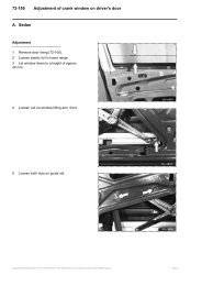
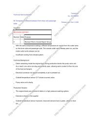
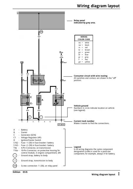
A - Battery<br />
B - Starter<br />
C - Generator (GEN)<br />
C1 - Voltage Regulator (VR)<br />
D - Ignition/Starter Switch<br />
S162 - Fuse -1- (30) in fuse bracket / battery<br />
S163 - Fuse -2- (30) in fuse bracket / battery<br />
T4e - 4-Pin Connector, on transmission<br />
T10a - 10-Pin Connector, on protective housing for<br />
control module, in engine compartment, left<br />
1 - Ground strap, battery to body<br />
2 - Ground strap, transmission to body<br />
500 - Screw connection -1- (30), on relay panel<br />
Edition ESIS<br />
2<br />
1<br />
M<br />
D/50<br />
2,5<br />
ro/sw<br />
T4e/1<br />
50<br />
97 -08151<br />
T10a/1<br />
B<br />
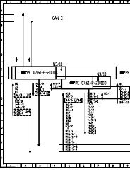
<strong>Wiring</strong> <strong>diagram</strong> <strong>layout</strong><br />
Relay panel<br />
Indicated by grey area.<br />
WIRING<br />
COLOR CODE<br />
ws = white<br />
sw = black<br />
ro = red<br />
br = brown<br />
gn = green<br />
bl = blue<br />
gr = grey<br />
li = lilac<br />
ge = yellow<br />
Consumer circuit with wire routing<br />
All switches and contacs are shown in the ”off”<br />
position.<br />
Vehicle ground<br />
Numbersincircleindicatelocationonvehicle<br />
(see legend).<br />
Current track number<br />
Makes it easier to find the connections.<br />
Legend<br />
In all wiring <strong>diagram</strong>s the same component<br />
designation (code) is used for a particular<br />
component; for example, always A for battery.<br />
<strong>Wiring</strong> <strong>diagram</strong> <strong>layout</strong> I
How to read wiring <strong>diagram</strong>s<br />
17<br />
16<br />
15<br />
14<br />
13<br />
12<br />
11<br />
10<br />
31<br />
a<br />
c<br />
0,5<br />
sw<br />
T45/38 T45/15<br />
T4/4<br />
362<br />
T6/2<br />
0,5<br />
sw<br />
0,5<br />
ws<br />
sw<br />
T45/29<br />
T4/3<br />
37<br />
1,0<br />
ws/ro<br />
ws<br />
T<br />
J257<br />
4/1<br />
G39<br />
T4/2<br />
1,0<br />
br/sw<br />
32<br />
1,5<br />
br/ro<br />
T45/1<br />
T28a/<br />
17<br />
11<br />
0,5<br />
gn/ge<br />
T45/3<br />
19/15 17/30<br />
16/85 6/30<br />
0,5<br />
br/ge<br />
12<br />
T45/28<br />
J 17 4<br />
43 44 45 46 47 48 49 50 51 52 53 54 55 56<br />
97 -08152<br />
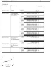
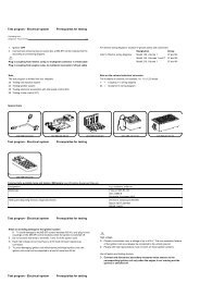
II How to read wiring <strong>diagram</strong>s<br />
J<br />
0,5<br />
sw<br />
S3/3<br />
114<br />
1,0<br />
ro<br />
0,5<br />
ro<br />
30<br />
T45/25 T45/21<br />
S2/5<br />
S3/5<br />
21<br />
18 20<br />
22 24<br />
E11<br />
0,5<br />
ro<br />
N80 6<br />
2<br />
1<br />
S3/4 S3/2 S3/1<br />
504<br />
4,0<br />
bl<br />
28<br />
S228<br />
15A<br />
28a<br />
1,0<br />
ge/sw<br />
1 3<br />
G M G<br />
1,0<br />
br<br />
4 2<br />
135<br />
0,5<br />
li/ws<br />
0,5<br />
br/ws<br />
31<br />
b<br />
c<br />
1<br />
2<br />
3<br />
4<br />
5<br />
6<br />
7<br />
8<br />
9<br />
Edition ESIS
1 - Relay location number<br />
Indicates location on relay panel.<br />
2 - Arrow<br />
Indicates wiring circuit is continued on the previous and/or next page.<br />
3 - Connection designation - relay control module on relay panel<br />
Shows the individual terminals in a multi-point connector.<br />
For example: contact 24 on terminal 4 on relay panel.<br />
4 - Diagram of threaded pin on relay panel<br />
White circle shows a detachable connection.<br />
5 - Fuse designation<br />
For example: S228 = Fuse number 28, 15 amps, in fuse holder<br />
6 - Reference of wire continuation (current track number)<br />
Number in frame indicates current track where wire is continued.<br />
7 - Wire connection designation in wiring harness<br />
Location of wire connections are indicated in the legend.<br />
8 - Terminal designation<br />
Designation which appears on actual component and/or terminal number of a multi-point<br />
connector.<br />
9 - Ground connection designation in wire harness<br />
Locations of ground connections are indicated in legend.<br />
10 - Component designation<br />
Use legend at bottom of page to identify the component code.<br />
11 - Component symbols (see page IV - VI)<br />
12 - Wire cross-section size (in mm2 )andwirecolors<br />
Abbreviations are explaining in color chart beside the wiring <strong>diagram</strong>.<br />
13 - Component symbol with open drawing side<br />
Indicated component is continued on another wiring <strong>diagram</strong>. The number of corresponding<br />
wiring <strong>diagram</strong> can taken from list of contents.<br />
14 - Internal connections (thin lines)<br />
These connections are not wires. Internal connections are current carrying and are listed to allow<br />
tracing of current flow inside components and wiring harness.<br />
15 - Reference of continuation of wire to component<br />
For example: Control module for anti-theft immobilizer J362 on 6-Pin Connector, terminal 2<br />
16 - Relay panel connectors<br />
Shows wiring of multi-point or single connectors on relay panel<br />
For example: S3/3 - Multi-point connector S3, terminal 3<br />
17 - Reference of internal connection continuation<br />
Letters indicate where connection continues on the previous and/or next page.<br />
Edition ESIS<br />
How to read wiring <strong>diagram</strong>s<br />
How to read wiring <strong>diagram</strong>s III
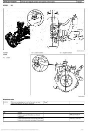
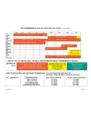
Symbolsusedinwiring<strong>diagram</strong>s<br />
M<br />
Â<br />
G<br />
Fuse<br />
Thermo-fuse<br />
(Circuit Breaker)<br />
Battery<br />
Starter<br />
Generator (GEN)<br />
Ignition Coil<br />
Distributor (electronic)<br />
Spark plug connector<br />
and plug<br />
Glow plug<br />
Heater element<br />
IV Symbols used for wiring <strong>diagram</strong>s<br />
Â<br />
Â<br />
Â<br />
Switch<br />
(manually operated)<br />
Switch<br />
(thermally operated)<br />
Push putton switch<br />
(manually operated)<br />
Switch<br />
(mechanically operated)<br />
Switch<br />
(pressure operated)<br />
Multiple switch<br />
(manually operated)<br />
Resistance<br />
Variable resistor<br />
(Rheostat)<br />
Resistor<br />
temperature dependent<br />
Heater element<br />
temperature dependent<br />
Relay<br />
97 -12201<br />
Edition ESIS
Edition ESIS<br />
Diode<br />
Zener diode<br />
Diode<br />
light sensitiv<br />
Light bulb<br />
Light bulb<br />
(dual filament)<br />
LED<br />
Interior light<br />
Instrument<br />
(Gauge)<br />
Electronic control<br />
module<br />
Rear window defogger<br />
heat element<br />
Cigarette lighter<br />
Symbolsusedinwiring<strong>diagram</strong>s<br />
Solenoid valve<br />
Magnetic clutch<br />
Wire connector<br />
Pin connector<br />
Multi-point connector<br />
at component<br />
Internal connections<br />
in component<br />
Wire connection<br />
detachable<br />
Wire connection<br />
fixed<br />
Wire connection in<br />
wiring harness<br />
Resistance wire<br />
Shield wire<br />
97 -08153<br />
Symbols used for wiring <strong>diagram</strong>s V
Symbolsusedinwiring<strong>diagram</strong>s<br />
M<br />
M<br />
VI Symbols used for wiring <strong>diagram</strong>s<br />
M<br />
Control motor,<br />
headlight range adjustment<br />
Motor<br />
Wiper motor<br />
2-speed<br />
Crankshaft position sensor<br />
(CKP)<br />
Knock sensor (KS)<br />
Analog clock<br />
Digital clock<br />
Multi-function<br />
indicator<br />
Airbag spiral spring<br />
Speed sensor<br />
Horn<br />
Speeker<br />
Antenna with electronic<br />
antenna amplifier<br />
Radio<br />
Heated oxygen sensor<br />
97 -08154<br />
Edition ESIS
Edition ESIS<br />
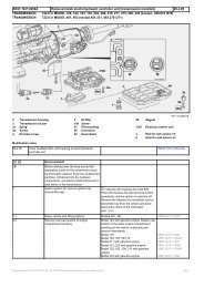
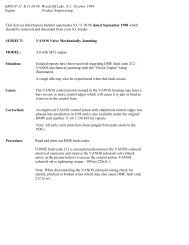
Explanation of troubleshooting procedures<br />
Starting with the reported problem, troubleshooting procedures show step-by-step what is checked and how it is checked<br />
in order to find the problem in the quickest and most reliable way. If several causes (of a problem) are possible in one system,<br />
a test procedure is used for diagnosis.<br />
Structure of a Test step:<br />
What is checked (assumed problem)<br />
How is it checked<br />
Cause of problem/repair<br />
instructions<br />
Example of a troubleshooting procedure:<br />
Test results<br />
To next test<br />
Open circuit in relay panel between connector terminals A4 and D2<br />
- Connect terminal D2 of multi-point connector to ground<br />
using Connector Test Kit VW 1594<br />
Warning lamp lights Warning lamp does not light<br />
Replace relay panel To next test<br />
Explanation of troubleshooting procedures VII