Indoor Pedestrian Navigation using an INS/EKF framework for Yaw ...
Indoor Pedestrian Navigation using an INS/EKF framework for Yaw ...
Indoor Pedestrian Navigation using an INS/EKF framework for Yaw ...

You also want an ePaper? Increase the reach of your titles
YUMPU automatically turns print PDFs into web optimized ePapers that Google loves.
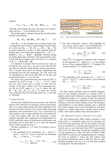
equation:δx k|k = δx k|k−1 + K k ·[m k − Hδx k|k−1 ], (16)where K k is the Kalm<strong>an</strong> gain, m k is the actual error measurement,<strong>an</strong>d δx k|k−1 is the predicted error state.The Kalm<strong>an</strong> gain is calculated during the correction phasewith the usual <strong>for</strong>mula:K k = P k|k−1 H T (HP k|k−1 H T + R k ) −1 . (17)where P k|k−1 is the estimation error covari<strong>an</strong>ce matrix, thatis computed at time k based on measurements received at timek-1, in this way: P k|k−1 = Φ k−1 P k−1|k−1 Φ T k−1 + Q k−1. Thecovari<strong>an</strong>ce matrix P k|k at time k is then computed <strong>using</strong> theKalm<strong>an</strong> gain in the Joseph <strong>for</strong>m equation: P k|k = (I 15×15 −K k H)P k|k−1 (I 15×15 − K k H) T + K k R k K T k . Similarly, duringthe update phase after corrections with measurements at timek, the predicted covari<strong>an</strong>ce matrix <strong>for</strong> time k+1 is computedas: P k+1|k = Φ k P k|k Φ T k + Q k.It is import<strong>an</strong>t to mention that the non-bias error terms ofthe filtered state vector, δx k|k , are reset to zero after the <strong>INS</strong>uses them to refine the current attitude, velocity <strong>an</strong>d position.This is because those errors are already compensated <strong>an</strong>dincorporated into the <strong>INS</strong> estimations. The only terms thatare maintained over time in the <strong>EKF</strong> filter are the gyro <strong>an</strong>daccelerometer biases, i.e. δω b k <strong>an</strong>d δab k .The actual error measurement m k that feeds the <strong>EKF</strong>, iscalculated <strong>for</strong> ZUPT as: m k = v k|k−1 − [0,0,0], wherethe zero vector me<strong>an</strong>s that at st<strong>an</strong>ce we know that thevelocity of the foot is almost zero. The measurement matrix,H, <strong>for</strong> ZUPT update is a 3 by 15 matrix like this:H = [0 3×3 , 0 3×3 , 0 3×3 , I 3×3 , 0 3×3 ]. It selects the velocityerror components from the error state matrix δx k , i.e. the 10thto 12th terms.C. St<strong>an</strong>ce detectionThe <strong>EKF</strong> gets feedback from measurements, only when theperson’s foot is detected to be stationary on the ground (totallystill, or in a st<strong>an</strong>ce phase during walk). Most algorithms in theliterature <strong>for</strong> st<strong>an</strong>ce detection rely on basic signal processingtechniques with accelerometers [5], [13] or gyroscopes [2].They properly work in m<strong>an</strong>y situations but occasionally failin slow <strong>an</strong>d r<strong>an</strong>dom walk [13]. We implement a multiconditionalgorithm, that complements the implementation of[10] by <strong>using</strong> both sources of in<strong>for</strong>mation (accelerometers <strong>an</strong>dgyroscopes) <strong>an</strong>d <strong>an</strong> order filter so as to make the detectionprocess robust enough (see Fig. 3).The three conditions (C1, C2 <strong>an</strong>d C3) to declare a foot asstationary are:1) The magnitude of the acceleration, |a k | = [a b k (1)2 +a b k (2)2 + a b k (3)2 ] 0.5 must be between two thresholds(th amin = 9 <strong>an</strong>d th amax = 11 m/s 2 ).C1 ={1 thamin < |a k | < th amax0 otherwise. (18)St<strong>an</strong>ce & Still phase detectionC1: Magnitude of acceleration conditionC2: Local vari<strong>an</strong>ce of acceler. conditionC3: Angular rate conditionFig. 3.AccelerationIMUAngular rateAND Medi<strong>an</strong> filter St<strong>an</strong>ce & StilldetectionEvent detectionSetup measurement <strong>for</strong> <strong>EKF</strong>St<strong>an</strong>ce <strong>an</strong>d Still detection block used in the IEZ <strong>framework</strong>.2) The local acceleration vari<strong>an</strong>ce, which highlights thefoot activity, must be above a given threshold (th σa =3 m/s 2 ). The local vari<strong>an</strong>ce is computed this way:σ 2 a b k= 12s+1k+s∑j=k−s(a b k −a b k )2 , (19)where a b kis a local me<strong>an</strong> acceleration value, computedby this expression:a b k = 1 ∑ k+s2s+1 q=k−s a q, <strong>an</strong>dsdefinesthe size of the averaging window (s = 15 samples). Thesecond condition C2 is satisfied when:C2 ={ 1 σa bk> th σa0 otherwise. (20)3) The magnitude of the gyroscope, |ω k | = [ω b k (1)2 +ω b k (2)2 + ω b k (3)2 ] 0.5 , must be below a given threshold(th ωmax = 50 o /s).C3 ={ 1 |ωk | < th ωmax0 otherwise. (21)The three logical conditions must be satisfied simult<strong>an</strong>eously<strong>for</strong> foot stationary detection, so a logical “AND” isapplied, <strong>an</strong>d the result is filtered out <strong>using</strong> a medi<strong>an</strong> filter witha neighboring window of 11 samples in total. The registeredlogical “1”s mark the St<strong>an</strong>ce phase that occurs when the foot isstationary on the floor (while walking, or not). The Still phase,corresponding to a non-walking stationary foot, is detectedfrom st<strong>an</strong>ce samples that are not surrounded by non-st<strong>an</strong>cesamples in a window larger th<strong>an</strong> 2 seconds. Figure 4 showsresults of this multi-condition st<strong>an</strong>ce detection process.III. METHODS TO REDUCE THE DRIFT IN HEADINGThe IEZ Kalm<strong>an</strong>-based PDR method presented in lastsection (Fig. 1), accumulates large errors in orientation dueto the bias in the gyroscopes. IEZ c<strong>an</strong> not estimate it becausethe yaw orientation (ψ k ), <strong>an</strong>d the gyroscopic bias (δω b ) in thevertical axis, are not observable from ZUPT measurementsalone [14]. Next subsections describe the integration in IEZof some approaches to reduce the drift in heading: ZARU[10], HDR [12], <strong>an</strong>d the use of magnetometers as a compass.We focus on methods to reduce the drift without <strong>using</strong><strong>an</strong>y external infrastructure such as GPS <strong>an</strong>d LPS, nor mapmatchingtechniques. See Fig. 5 to view how these methodsare integrated in the IEZ <strong>framework</strong>.