Design and Implementation of a Neuro-Fuzzy System for ...
Design and Implementation of a Neuro-Fuzzy System for ...
Design and Implementation of a Neuro-Fuzzy System for ...

Create successful ePaper yourself
Turn your PDF publications into a flip-book with our unique Google optimized e-Paper software.
<strong>Design</strong> <strong>and</strong> <strong>Implementation</strong> <strong>of</strong> a <strong>Neuro</strong>-<strong>Fuzzy</strong> <strong>System</strong> <strong>for</strong><br />
Longitudinal Control <strong>of</strong> Autonomous Vehicles<br />
Joshué Pérez, Agustín Gajate, Vicente Milanés, Enrique Onieva, Matilde Santos<br />
Abstract— The control <strong>of</strong> nonlinear systems has been<br />
putting especial attention in the use <strong>of</strong> Artificial Intelligent<br />
techniques, where fuzzy logic presents one <strong>of</strong> the best<br />
alternatives due to the exploit <strong>of</strong> human knowledge.<br />
However, several fuzzy logic real-world applications use<br />
manual tuning (human expertise) to adjust control systems.<br />
On the other h<strong>and</strong>, in the Intelligent Transport <strong>System</strong>s<br />
(ITS) field, the longitudinal control (throttle <strong>and</strong> brake<br />
management) is an important topic because external<br />
perturbations can generate uncom<strong>for</strong>table accelerations as<br />
well as unnecessary fuel consumption. In this work, we<br />
utilize a neuro-fuzzy system to use human driving knowledge<br />
to tune <strong>and</strong> adjust the input-output parameters <strong>of</strong> a fuzzy ifthen<br />
system. The neuro-fuzzy system considered in this work<br />
is ANFIS (Adaptive-Network-based <strong>Fuzzy</strong> Inference<br />
<strong>System</strong>). Results show several improvements in the control<br />
system adjusted by neuro-fuzzy techniques in comparison to<br />
the previous manual tuned controller, mainly in com<strong>for</strong>t <strong>and</strong><br />
efficient use <strong>of</strong> actuators.<br />
I. INTRODUCTION<br />
1 Cruise Control (CC), emergency stop <strong>and</strong> velocity<br />
tracking control are the more common longitudinal<br />
control applications, which have been extensively studied<br />
in the fields <strong>of</strong> mobile robots <strong>and</strong> Intelligent<br />
Transportation <strong>System</strong>s (ITS) [1]. Indeed, in commercial<br />
vehicles, it is progressively implementing safer <strong>and</strong> more<br />
com<strong>for</strong>table control <strong>for</strong> drivers, acting on throttle <strong>and</strong><br />
brake [2].<br />
Some solutions <strong>for</strong> controlling the longitudinal<br />
actuators have been based on complex models <strong>of</strong> the<br />
autonomous longitudinal system [3]. However, other<br />
authors have demonstrated that fuzzy logic <strong>of</strong>fers a good<br />
way to model <strong>and</strong> control complex system, like vehicle’s<br />
actuators [4].<br />
In 1965, Zadeh defined the fuzzy logic sets <strong>of</strong> a fuzzy<br />
system [5]. Then Tagaki <strong>and</strong> Sugeno proved this kind <strong>of</strong><br />
system (using trapezoidal input, if-then rules <strong>and</strong><br />
singleton consequents) can be applied in modelling <strong>and</strong><br />
control <strong>of</strong> mobile robots [4], [6].<br />
The main advantage <strong>of</strong> a fuzzy controller is that it is not<br />
necessary an exact mathematical model <strong>of</strong> the system to<br />
be controlled. Moreover, this controller can emulate the<br />
This work was supported in part by Plan Nacional, Spain, under<br />
Project TRANSITO under TRA2008-06602-C03-01, by the Comisión<br />
Interministerial de Ciencia y Tecnología, Spain, under Project GUIADE<br />
(Spain Ministerio de Fomento T9/08).<br />
Joshue Perez (Corresponding author), Agustin Gajate, Vicente<br />
Milanés, <strong>and</strong> Enrique Onieva are with the Instituto de Automática<br />
Industrial, CSIC, Arg<strong>and</strong>a del Rey, Madrid, Spain; Email: {jperez,<br />
agajate, vmilanes, onieva}@iai.csic.es<br />
M. Santos is with the Department <strong>of</strong> Computer Architecture <strong>and</strong><br />
Automatic Control, Facultad de In<strong>for</strong>matica, Universidad Complutense<br />
de Madrid, 28040-Madrid, Spain (e-mail: msantos@dacya.ucm.es).<br />
behaviour from expert drivers due to knowledge base,<br />
using the human experience, <strong>and</strong> if-then rules.<br />
However, there are some basic aspects in the if-then<br />
systems that require special attention. The main aspect is<br />
that there aren’t st<strong>and</strong>ard methods <strong>for</strong> trans<strong>for</strong>ming human<br />
knowledge or experience into the rule base <strong>and</strong> database<br />
<strong>of</strong> a fuzzy system. Moreover, there is a need <strong>of</strong> automatic<br />
<strong>and</strong> effective methods <strong>for</strong> tuning the membership<br />
functions (MF), rule base <strong>and</strong> output parameters <strong>of</strong> the<br />
fuzzy systems [7].<br />
<strong>Neuro</strong>-<strong>Fuzzy</strong> <strong>System</strong>s (NFS) appear in this context<br />
merging Artificial Neural Networks (ANN) <strong>and</strong> <strong>Fuzzy</strong><br />
Inference <strong>System</strong> (FIS). <strong>Neuro</strong>-<strong>Fuzzy</strong> systems combine<br />
the semantic transparency <strong>of</strong> rule-based fuzzy systems<br />
with the learning capability <strong>of</strong> neural networks. There<strong>for</strong>e,<br />
NFS are capable <strong>of</strong> representing systems by means <strong>of</strong> ifthen<br />
rules represented in a network structure, which<br />
learning algorithms from the area <strong>of</strong> artificial neural<br />
networks can be applied [8].<br />
Nowadays, several approaches use neuro-fuzzy systems<br />
to control nonlinear systems or to adjust controllers [9].<br />
Most <strong>of</strong> them use the pioneering neuro-fuzzy system,<br />
Adaptive <strong>Neuro</strong> <strong>Fuzzy</strong> Inference <strong>System</strong> (ANFIS) [10]<br />
because <strong>of</strong> its simplicity <strong>and</strong> its computationally efficient<br />
procedure [8].<br />
In ITS, neuro-fuzzy systems had been used <strong>for</strong><br />
modelling traffic flow behaviour, using a specific class <strong>of</strong><br />
neuro-fuzzy system known as the Pseudo Outer-Product<br />
<strong>Fuzzy</strong>-Neural Network, with Truth-Value-Restriction<br />
method (POPFNN-TVR) [11].<br />
In recent years, some applications with vehicles which<br />
use neuro-fuzzy systems have appeared. Most <strong>of</strong> them<br />
control the vibration passenger’s vehicle suspension,<br />
improving the com<strong>for</strong>t in the vehicle body [1]. In other<br />
applications neuro-fuzzy velocity tracking control with<br />
rein<strong>for</strong>cement learning has been implemented in a real<br />
prototype, but only tested in special condition, not in real<br />
tracks (on a drive roller)[12], <strong>and</strong> using inconsistent data<br />
in the neural network training.<br />
The AUTOPIA group, where this work was developed,<br />
is part <strong>of</strong> the Institute <strong>of</strong> Industrial Automation <strong>of</strong> the<br />
Spanish National Research Council (IAI-CSIC). From the<br />
beginning, its main goal has been to develop control<br />
strategies <strong>for</strong> mass-produced vehicles [14]. The main<br />
purpose <strong>of</strong> this work is to improve previous fuzzy<br />
controllers developed in the group [15], taking the<br />
experience <strong>of</strong> different expert drivers <strong>and</strong> considering the<br />
com<strong>for</strong>t <strong>and</strong> efficient use <strong>of</strong> actuators. For this purpose, a<br />
neuro-fuzzy system is considered, specifically an<br />
Adaptive Network Based <strong>Fuzzy</strong> Inference <strong>System</strong>
(ANFIS), where the previous rule base <strong>and</strong> the experience<br />
<strong>of</strong> the expert drivers have been used as start point.<br />
These experts are drivers that know the feature <strong>of</strong> the<br />
vehicle <strong>and</strong> the tested tracks, which has some slopes <strong>and</strong><br />
curves that have an effect on vehicle dynamic. To keep<br />
the reference speed in these conditions is difficult <strong>for</strong><br />
human drivers.<br />
This paper is organized as follows. In Section II, we<br />
describe the system, explaining the longitudinal actuators.<br />
An overview <strong>of</strong> the previous longitudinal control is<br />
presented in Section III. The real time experiments carried<br />
out with the neuro-fuzzy controller <strong>and</strong> a comparative<br />
between both controllers are described in section IV.<br />
Finally some remarks <strong>and</strong> conclusions are presented in<br />
Section V.<br />
vehicle.<br />
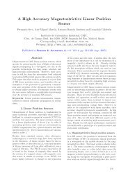
The control is based in a RTK -DGPS which provides<br />
centimetric accuracy. In order to follow a track, the path is<br />
followed manually <strong>and</strong> the sequence <strong>of</strong> points is read from<br />
the GPS. A map is then generated by a sequence <strong>of</strong> points<br />
with a speed value attached, <strong>and</strong> manually added to each<br />
line. Later, when following the track in automatic mode,<br />
the GPS readings allow to determine two variables: the<br />
segment <strong>of</strong> the track where the car is, <strong>and</strong> the lateral<br />
distance to the desired point.<br />
The segment <strong>of</strong> the map is used to control the speed,<br />
<strong>and</strong> the lateral displacement is used to control the steering.<br />
Fig. 2 shows a diagram <strong>of</strong> the control architecture<br />
implemented in the test vehicle.<br />
II. AUTONOMOUS VEHICLE. EXPERIMENTAL<br />
PLATFORM<br />
Researching in autonomous vehicles field has special<br />
interest because they can help to reduce traffic accidents<br />
<strong>and</strong> to improve the com<strong>for</strong>t in the driving. A com<strong>for</strong>table<br />
driving can be achieved with an efficient use <strong>of</strong> the<br />
longitudinal actuators. Although the lateral actions may<br />
have an effect on the longitudinal dynamic, in this work<br />
only throttle <strong>and</strong> brake will be considered as output<br />
control variables.<br />
The test vehicle used in this work is propelled by a<br />
gasoline motor. Its steering assistance is electric. The<br />
throttle pedal generates two signals: one <strong>of</strong> them from 0 to<br />
5 volts, <strong>and</strong> the range <strong>of</strong> the other one is half <strong>of</strong> it. That is<br />
used as control action. The CAN bus <strong>of</strong> the vehicle<br />
provides the control signal <strong>for</strong>m the speed <strong>and</strong> steering<br />
wheel angle given by the sensors.<br />
In order to automate the throttle, two signals generated<br />
by a digital to analogue converter embedded in the<br />
computer feed the motor control.<br />
Fig. 1. Test vehicle <strong>and</strong> the actuators<br />
The steering is controlled as follows. The wires lines<br />
leading to the assistance electric motor are cut <strong>and</strong><br />
replaced by a line taken directly from the battery. That is,<br />
a modulated width pulse is codified according to the<br />
analogue signal controlled by the computer.<br />
An additional braking system has been added without<br />
disabling the original one. It is <strong>for</strong>med by a pump whose<br />
pressure is controlled by an analogue signal, also<br />
generated by the computer. Fig. 1 shows the actuated<br />
Fig. 2. Vehicle control scheme.<br />
The control <strong>of</strong> the autonomous vehicle is divided into<br />
three main phases: perception, decision, <strong>and</strong> action. The<br />
first phase is responsible <strong>of</strong> receiving in<strong>for</strong>mation from<br />
the environment (position, speed, in<strong>for</strong>mation from others<br />
vehicles <strong>and</strong> infrastructure), through the different sensors<br />
<strong>and</strong> communication system. The decision phase is<br />
responsible <strong>for</strong> evaluating the conditions obtained in the<br />
perception phase, <strong>and</strong> sends the target to the action phase.<br />
III. FUZZY LOGIC LONGITUDINAL CONTROL<br />
The decision phase <strong>of</strong> the control <strong>of</strong> our autonomous<br />
vehicle is divided into two tasks: to determinate the<br />
conditions <strong>of</strong> the environment <strong>and</strong> to send the control<br />
references to the throttle, brake <strong>and</strong> the steering wheel.<br />
This work is only focused on the longitudinal control.<br />
The autonomous vehicle control system is based on<br />
fuzzy logic. An experimental fuzzy coprocessor called<br />
ORBEX (Spanish acronym <strong>of</strong> Experimental <strong>Fuzzy</strong><br />
Coprocessor) has been developed [14]. It is an inference<br />
motor that uses natural-language-based inputs. It allows<br />
variables to be defined <strong>and</strong> combined in rules <strong>of</strong> the <strong>for</strong>m:<br />
“IF…THEN...”. In the inference method, it uses<br />
Mamdani-type [16], <strong>and</strong> singleton-type membership<br />
functions to codify the output variables, as Tagaki <strong>and</strong><br />
Sugeno suggested [6]. The goal <strong>of</strong> the fuzzy logic is to use<br />
the expert knowledge to emulate the behaviour <strong>of</strong> human<br />
drivers.<br />
The starting point <strong>of</strong> this work can be found in previous<br />
works [15][17], where the control <strong>of</strong> both actuators on an<br />
electric van <strong>and</strong> on the gasoline vehicle used here was<br />
implemented with promising results. Details on the<br />
membership functions, rule base description, singleton<br />
outputs can be found in [17]. This controller defines two<br />
fuzzy outputs <strong>for</strong> each actuator, the throttle <strong>and</strong> brake.<br />
Also, a switch in the output <strong>of</strong> the control makes that both<br />
actuators cannot work at the same time.<br />
The input variables <strong>of</strong> the longitudinal control are:
error_speed <strong>and</strong> acceleration. The first is the different<br />
between the actual speed <strong>and</strong> the target speed <strong>of</strong> the<br />
vehicle (km/h). The second is the longitudinal<br />
acceleration or the variation <strong>of</strong> the vehicle speed at each<br />
time instant. The same membership functions are used to<br />
describe both linguistic variables.<br />
Fig. 3 shows the behaviour <strong>of</strong> the vehicle with this<br />
fuzzy controller [17]. A segment <strong>of</strong> a real circuit at our<br />
facilities was selected <strong>for</strong> the experiments. Some slope<br />
(less than 4 degrees) <strong>and</strong> curves <strong>of</strong> the tracks are<br />
considered as external perturbations, affecting the<br />
longitudinal dynamics <strong>of</strong> the vehicle.<br />
Two target speeds were defined <strong>for</strong> these experiments,<br />
10 <strong>and</strong> 20 km/h. The upper part <strong>of</strong> Fig. 3 shows the target<br />
<strong>and</strong> actual speed <strong>of</strong> the route. At around 40 <strong>and</strong> 70<br />
seconds, the vehicle takes two slopes. In these situations,<br />
the vehicle loses some power <strong>and</strong> moves slightly from<br />
reference.<br />
researchers in various fields <strong>of</strong> science <strong>and</strong> engineering<br />
because <strong>of</strong> the increasing necessity <strong>of</strong> developing adaptive<br />
intelligent systems to solve real world problems. Neural<br />
networks learn by adjusting the weight <strong>of</strong> the connections<br />
between the nodes (learning ability). Moreover, fuzzy<br />
inference systems provide an efficient environment or<br />
computing framework based on the concepts <strong>of</strong> fuzzy set<br />
theory, fuzzy if-then rules, <strong>and</strong> fuzzy reasoning. The<br />
advantages <strong>of</strong> combining neural networks <strong>and</strong> fuzzy<br />
inference systems are clearly presented in [8-13].<br />
The Adaptive-Network-Based <strong>Fuzzy</strong> Inference <strong>System</strong><br />
(ANFIS) was one <strong>of</strong> the first neuro-fuzzy systems<br />
developed [8]. Its principle is based on extracting fuzzy<br />
rules at each level <strong>of</strong> a neural network. Once the rules<br />
have been obtained, they provide the necessary<br />
in<strong>for</strong>mation on the overall behaviour <strong>of</strong> the process.<br />
ANFIS implements the Takagi-Sugeno model <strong>for</strong> the<br />
structure <strong>of</strong> the fuzzy system’s if-then rules. The ANFIS<br />
architecture has five layers, as shown in Fig. 4. The nodes<br />
represented by squares have adjustable parameters,<br />
whereas the nodes represented by circles are fixed ones.<br />
Fig. 4. ANFIS architecture <strong>of</strong> the system<br />
Fig. 3. Longitudinal fuzzy control: Vehicle speeds, <strong>Fuzzy</strong> outputs,<br />
Longitudinal acceleration.<br />
The fuzzy outputs, throttle <strong>and</strong> brake, are shown in the<br />
middle <strong>of</strong> Fig. 3. In the lower part <strong>of</strong> the same figure, the<br />
acceleration is presented. In this study, the acceleration<br />
has two roles: it is an input <strong>of</strong> the fuzzy control <strong>and</strong> it is<br />
also the most important parameter to measure the com<strong>for</strong>t<br />
when driving.<br />
The implemented fuzzy system has many advantages:<br />
low error, fast response, <strong>and</strong> robustness [18]. However,<br />
the system can be improved by considering the com<strong>for</strong>t<br />
<strong>and</strong> efficiency use <strong>of</strong> the actuators. The aim <strong>of</strong> this work<br />
is then to improve the system response (safety <strong>and</strong><br />
com<strong>for</strong>t) taking advantage <strong>of</strong> the experience <strong>of</strong> different<br />
expert drivers to enhance the controller. For this purpose a<br />
neuro-fuzzy system has been implemented.<br />
IV. LONGITUDINAL NEURO-FUZZY CONTROL<br />
The fusion <strong>of</strong> Artificial Neural Networks <strong>and</strong> <strong>Fuzzy</strong><br />
Inference <strong>System</strong>s has attracted growing interest among<br />
The ANFIS system used in this work is built upon the<br />
fuzzy controller shown in [17]. There<strong>for</strong>e the system has<br />
two inputs (Speed_Error <strong>and</strong> Acceleration) <strong>and</strong> one output<br />
(Throttle/Brake). Each input has three membership<br />
functions, leading to 9 rules. The output <strong>of</strong> the neur<strong>of</strong>uzzy<br />
system is in the range [-1,1], where the interval [-<br />
1,0) corresponds to the brake <strong>and</strong> the range (0,1]<br />
corresponds to the throttle.<br />
The fuzzy controller has been proved to present a<br />
correct per<strong>for</strong>mance. However, in certain situations it has<br />
been found that a skilled driver results in a s<strong>of</strong>ter driving,<br />
that is, safer <strong>and</strong> more com<strong>for</strong>table. For this reason<br />
ANFIS is used to provide the expert operator's knowledge<br />
to the system <strong>of</strong> rules already defined.<br />
The error speed <strong>and</strong> the acceleration values were<br />
recorded, as well as the value <strong>of</strong> the accelerator <strong>and</strong> brake<br />
on a tour taken an expert driver. Three expert drivers<br />
followed the same track that was presented in section III.<br />
Figure 5 shows the response <strong>of</strong> the system <strong>for</strong> the three<br />
experts.<br />
Due to the physical conditions <strong>of</strong> the tracks, the experts<br />
had some difficulties trying to keep the exact speed. All <strong>of</strong><br />
them considered the reference speed like the maximum<br />
limit, <strong>and</strong> they try to use only the throttle <strong>and</strong> not the<br />
brake.
The values <strong>of</strong> the singleton outputs are listed in Table<br />
II:<br />
Fig. 5. Experiments by expert drivers.<br />
The parameters chosen <strong>for</strong> training the ANFIS system<br />
<strong>and</strong> its structure are as follows (Table I):<br />
TABLE I: ANFIS SYSTEM CONFIGURATION<br />
Algorithm<br />
<strong>System</strong><br />
Membership<br />
functions type<br />
Number <strong>of</strong><br />
membership<br />
functions<br />
Inference system<br />
ANFIS<br />
Twoinputs/singleoutput<br />
Trapezoidal<br />
3<br />
Takagi-Sugeno<br />
(constant)<br />
Number <strong>of</strong> rules 9<br />
Iterations 500<br />
Learning rate 0.001<br />
Training algorithm<br />
Training data set<br />
Validation data set<br />
Back<br />
propagation<br />
510 samples<br />
(1 experiment)<br />
987 samples<br />
(2 experiments)<br />
TABLE II: OUTPUT VALUES OF THE NEURO-FUZZY RULES<br />
a01 0.005979<br />
a02 0.08839<br />
a03 0.1901<br />
a04 0.01084<br />
a05 0.2245<br />
a06 -0.101<br />
a07 -0.02014<br />
a08 0.09938<br />
a09 -0.2186<br />
V. REAL TIME EXPERIMENTS AND RESULTS<br />
The real time experiments show the behaviour <strong>of</strong> the<br />
proposed neuro-fuzzy controller working in the<br />
autonomous vehicle. They were carried out in the same<br />
condition <strong>of</strong> the experiments <strong>of</strong> Section III (with a fuzzy<br />
controller) <strong>and</strong> IV (expert drivers). That is, vehicle speeds<br />
between 10 km/h <strong>and</strong> 20 km/h <strong>and</strong> the same track.<br />
Fig. 6 shows a comparison between the membership<br />
function <strong>of</strong> the inputs <strong>and</strong> the singleton output <strong>for</strong> the<br />
fuzzy <strong>and</strong> the neuro-fuzzy controllers. Both membership<br />
functions are triangular or trapezoidal. Black lines<br />
represent the functions generated by ANFIS, <strong>and</strong> gray<br />
lines correspond to the fuzzy one. As it is possible to see,<br />
acceleration is the variable that has most changed, from a<br />
trapezoidal to triangular shape.<br />
The rule base <strong>of</strong> the longitudinal control generated by<br />
the neuro-fuzzy system is described by the following<br />
rules:<br />
IF Speed_error Negative AND Acceleration Negative<br />
THEN Output a05<br />
IF Speed_error Negative AND Acceleration Positive<br />
THEN Output a02<br />
IF Speed_error Negative AND Acceleration Null THEN<br />
Output a03<br />
IF Speed_error Positive AND Acceleration Negative<br />
THEN Output a06<br />
IF Speed_error Positive AND Acceleration Positive<br />
THEN Output a07<br />
IF Speed_error Positive AND Acceleration Null THEN<br />
Output a09<br />
IF Speed_error Null AND Acceleration Negative THEN<br />
Output a01<br />
IF Speed_error Null AND Acceleration Positive THEN<br />
Output a04<br />
IF Speed_error Null AND Acceleration Null THEN<br />
Output a08<br />
Fig. 6. Membership functions <strong>and</strong> singleton outputs generated by the<br />
neuro-fuzzy controller.
The first experiment was carried out on a track with<br />
curves around 90 degrees <strong>and</strong> two slopes, as in the<br />
previous experiments. The total distance is 400 metres<br />
long.<br />
The upper part <strong>of</strong> Fig. 7 shows the reference <strong>and</strong> the<br />
actual speed obtained by the neuro-fuzzy controller. It is<br />
possible to see as the system has leant to the expert drivers<br />
(Fig. 5), as it maintains the speed close to the lower limit<br />
<strong>of</strong> the speed. There is not overshoot on the response. It<br />
works as a cautious drive would do.<br />
When the vehicle is at around 50 <strong>and</strong> 80 seconds, it<br />
takes two slopes. The average <strong>of</strong> the speed in this<br />
experiment is lower than in the previous values shown in<br />
Fig. 3, that is, 13.75 km/h <strong>for</strong> the fuzzy control <strong>and</strong> 12.52<br />
km/h <strong>for</strong> the neuro-fuzzy one. This may be caused<br />
because the vehicle never surpasses the reference.<br />
The output <strong>of</strong> new controller is shown in the middle <strong>of</strong><br />
Fig. 7. The gray line corresponds to the fuzzy throttle<br />
output <strong>and</strong> the black one is fuzzy brake output.<br />
This new controller presents a better behaviour in terms<br />
<strong>of</strong> efficiency, since the motor consumes less fuel. The<br />
throttle is just around 0.2 when the reference speed<br />
changes (at the beginning <strong>of</strong> the experiment, <strong>and</strong> at<br />
around 30 <strong>and</strong> 70 seconds). In the rest <strong>of</strong> the experiment<br />
the output values are less that 0.05 in all the cases.<br />
The average <strong>of</strong> the fuzzy throttle output is 0.0454 <strong>for</strong><br />
the previous controller (Fig. 3), while <strong>for</strong> the new neur<strong>of</strong>uzzy<br />
controller is 0.0245. This means a reduction <strong>of</strong><br />
46.1% in the use <strong>of</strong> the motor acceleration.<br />
The fuzzy brake output also presents better results as<br />
the brake is just used when the reference speed is reduced.<br />
The behaviour is there<strong>for</strong>e closer to a human driver,<br />
who only uses the brake to stop or to cut down the speed<br />
in special situations, <strong>and</strong> not <strong>for</strong> keeping the speed (Cruise<br />
Control). Comparing both controllers, the reduction is<br />
about the 55.7% in terms <strong>of</strong> brake efficiency.<br />
In the middle <strong>of</strong> Fig. 3 we could see how the brake was<br />
applied to keep the reference at several instants. However,<br />
in Fig. 7, the brake is just used at around 50 <strong>and</strong> 95<br />
seconds, <strong>and</strong> it is never used during the rest <strong>of</strong> the<br />
experiment because is unnecessary (as expected when an<br />
expert is driving).<br />
Consequently, the longitudinal acceleration in the<br />
vehicle is reduced, as shown in the lower part <strong>of</strong> Fig. 7.<br />
The average <strong>of</strong> the acceleration has been reduced from<br />
0.0498 m/s2 to 0.0267 m/s2. This means a 46.43 % less,<br />
<strong>and</strong> there<strong>for</strong>e a significant improvement in the com<strong>for</strong>t <strong>of</strong><br />
the driving.<br />
VI. CONCLUSIONS<br />
This work presents the real time implementation <strong>of</strong> a<br />
neuro-fuzzy controller that has been applied to intelligent<br />
transportation systems. The purpose <strong>of</strong> this controller is to<br />
improve the response <strong>of</strong> a vehicle propelled by a gasoline<br />
motor. This neuro-fuzzy system enhances the per<strong>for</strong>mance<br />
<strong>of</strong> a previous fuzzy controller by incorporating the<br />
experience <strong>of</strong> expert drivers. The new fuzzy controller<br />
was tuned by considering the experiments carried out by<br />
three expert drivers. Although the knowledge base is still<br />
small, the neuro-fuzzy system was able to learn from<br />
these data, giving satisfactory results.<br />
The throttle <strong>and</strong> brake are used in a more efficiently<br />
way when this neuro-fuzzy controller is applied, like a<br />
good driver would do. The brake is only used when the<br />
vehicle must reduce the speed or stops, <strong>and</strong> the throttle is<br />
just used to keep the reference speed <strong>and</strong> to accelerate.<br />
These results have been shown by real time experiments<br />
on an autonomous gasoline vehicle.<br />
<strong>Neuro</strong>-fuzzy systems have many applications in ITS<br />
area. <strong>Design</strong>ing, tuning <strong>and</strong> implementation <strong>of</strong> the lateral<br />
control will be considered <strong>for</strong> future works. Moreover,<br />
neuro-fuzzy techniques will be used to model the<br />
behaviour <strong>of</strong> the vehicle, <strong>and</strong> we think that this will help<br />
us to improve the current controllers in the autonomous<br />
driving.<br />
The longitudinal control can also be improved if other<br />
variables are taking into account in the control loop. In<br />
future works, a multivariable system, considering<br />
longitudinal <strong>and</strong> transversal variables, may be designed.<br />
Moreover, the climate factor will also be considered.<br />
Fig. 7. Longitudinal neuro-fuzzy control: Vehicle speeds, <strong>Fuzzy</strong> outputs,<br />
Longitudinal acceleration.<br />
REFERENCES<br />
[1] J. P. Laumond, ed., "Robot Motion Planning <strong>and</strong> Control", vol.<br />
229. New York: Springer-Verlag, 1998.<br />
[2] S. E. Shladover, “Review <strong>of</strong> the state od development <strong>of</strong> advanced<br />
vehicle control systems (avcs),” Vehicle <strong>System</strong> Dynamics, vol.<br />
24, pp. 551–595, 1995.<br />
[3] S. Zhao, Y. Li, L. Zheng, <strong>and</strong> S. Lu, “Vehicle lateral stability<br />
control based on sliding mode control,” in Proc. IEEE International<br />
Conference on Automation <strong>and</strong> Logistics, 18–21 Aug. 2007, pp.<br />
638–642.<br />
[4] M. Sugeno <strong>and</strong> M. Nishida, “<strong>Fuzzy</strong> control <strong>of</strong> model car,” <strong>Fuzzy</strong><br />
Sets <strong>and</strong> <strong>System</strong>s. 16, 103-113 ,1985.<br />
[5] L. A. Zadeh, “<strong>Fuzzy</strong> sets,” Info. Contr., vol. 8, pp. 338–353,<br />
1965.T. Takagi <strong>and</strong> M. Sugeno, "<strong>Fuzzy</strong> identification <strong>of</strong> systems<br />
<strong>and</strong> its applications to modelling <strong>and</strong> control," IEEE Trans. Syst.,<br />
Man, Cybern., 15(1), 116-132, 1985.<br />
[6] T. Takagi <strong>and</strong> M. Sugeno, “<strong>Fuzzy</strong> identification <strong>of</strong> systems <strong>and</strong> its<br />
applications to modeling <strong>and</strong> control,” IEEE Trans. Syst., Man<br />
Cybern., vol. SMC-15, pp. 116–132, Jan./Feb. 1985.
[7] M. A. Denai, F. Palis, <strong>and</strong> A. Zeghbib, "Modeling <strong>and</strong> control <strong>of</strong><br />
non-linear systems using s<strong>of</strong>t computing techniques," Applied S<strong>of</strong>t<br />
Computing Journal, vol. 7, pp. 728-738, 2007.<br />
[8] J.-S. R. Jang, "ANFIS: adaptive-network-based fuzzy inference<br />
system," IEEE Transactions on <strong>System</strong>s, Man <strong>and</strong> Cybernetics,<br />
vol. 23, pp. 665-685, 1993.<br />
[9] R. Babuska <strong>and</strong> H. Verbruggen, "<strong>Neuro</strong>-fuzzy methods <strong>for</strong><br />
nonlinear system identification," Annual Reviews in Control, vol.<br />
27, pp. 73-85, 2003.<br />
[10] H. Chen, "Fuel Injection Control <strong>and</strong> Simulation <strong>of</strong> EFI Engine<br />
Based on ANFIS," in Intelligent Computation Technology <strong>and</strong><br />
Automation (ICICTA), 2008 International Conference on, 2008,<br />
pp. 191-194.<br />
[11] C. Quek, M. Pasquier, B. Lim, "A novel self-organizing fuzzy rulebased<br />
system <strong>for</strong> modelling traffic flow behaviour", Expert<br />
<strong>System</strong>s with applications, vol 36, pp. 167–178, 2009.<br />
[12] R. Vatankhah, M. Rahaeifard, A. Alasty, "Vibration control <strong>of</strong><br />
vehicle suspension system using adaptive critic-based neur<strong>of</strong>uzzy<br />
controller", 6th International Symposium on Mechatronics <strong>and</strong> its<br />
Applications, ISMA 2009.<br />
[13] J. XUE, W. ZHANG <strong>and</strong> Z. GONG, “Neur<strong>of</strong>uzzy velocity tracking<br />
control with rein<strong>for</strong>cement learning”, The ninth International<br />
Conference on electronic measurement & instruments,<br />
ICEMI`2009.<br />
[14] R. Garcia, T. De Pedro. "First Application <strong>of</strong> the ORBEX<br />
Coprocessor: Control <strong>of</strong> Unmanned Vehicles". EUSFLAT-<br />
ESTYLF Joint Conference. Mathware <strong>and</strong> S<strong>of</strong>t Computing, n. 7,<br />
vo12-3, 2000, pp. 265-273, 1999.<br />
[15] J.E. Naranjo “ACC+Stop&Go Maneuvers With Throttle <strong>and</strong> Brake<br />
<strong>Fuzzy</strong> Control” IEEE Transactions On Intelligent Transportation<br />
<strong>System</strong>s, VOL. 7, NO. 2, june,2006.<br />
[16] E. H. Mamdani, “Applications <strong>of</strong> fuzzy algorithms <strong>for</strong> simple<br />
dynamic plant,” Proc. IEEE, vol. 62, no. 12, pp. 1585–1588, Dec.<br />
1974.<br />
[17] E. Onieva, V. Milanés, C. González, T. de Pedro, J. Pérez, J.<br />
Alonso “Throttle <strong>and</strong> Brake Pedals Automation <strong>for</strong> Populated<br />
Areas”, ROBOTICA, 2009 (in Press).<br />
[18] V. Milanés, J. Pérez, E. Onieva <strong>and</strong> C. González “Controller <strong>for</strong><br />
Urban Intersections Based on Wireless Communications <strong>and</strong> <strong>Fuzzy</strong><br />
Logic” IEEE Transactions On Intelligent Transportation <strong>System</strong>s,<br />
Vol. 11, no. 1, pp. 243-248, March 2010. Depme pepempempempe